UAB Teltonika RUT955A GPS Tracker User Manual 2
UAB Teltonika GPS Tracker 2
Contents
User Manual 2
91
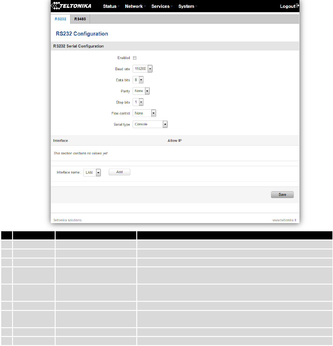
9.5 RS232/RS485
RS232 and RS485 functions are designed to utilize available serial interfaces of the router. Serial interfaces
provide possibility for legacy devices to gain access to IP networks.
9.5.1 RS232
Field name
Sample
Explanation
1.
Enabled
Enable/Disable
Check the box to enable the serial port function.
2.
Baud rate
300 / 115200
Select the communication speed of the serial interface.
3.
Data bits
5 - 8
Specifies how many bits will be used for character
4.
Parity
None / Odd / Even
Select the parity bit setting used for error detection during data
transfer.
5.
Stop bits
1 / 2
Specifies how many stop bits will be used to detect the end of
character
6.
Flow control
None / RTS- CTS / Xon-Xoff
Specifies what kind of characters to use for flow control
7.
Serial type
Console / Over IP / Modem
/ Modbus Gateway
Specifies function of serial interface
8.
Interface
LAN/ WAN/ VPN
Interface used for connection
9.
Allow IP
192.168.1.102
Allow IP connecting to server
92
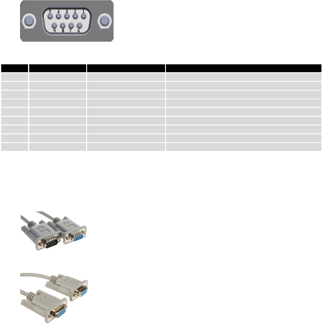
9.5.1.1 RS232 connector pinout
RS232 connector type on this device is DCE female. DCE stands for Data Communication Equipment.
Pin
Name*
Description*
Direction on this device
1
DCD
Data Carrier Detect
Output
2
RXD
Receive Data
Output
3
TXD
Transmit Data
Input
4
DTR
Data Terminal Ready
Input
5
GND
Signal Ground
-
6
DSR
Data Set Ready
Output
7
RTS
Ready To Send
Input
8
CTS
Clear to send
Output
9
RI
Ring indicator
Output (connected to +5V permanently via 4.7k resistor)
*The names and descriptions that indicate signal direction (such as TXD, RXD, RTS, CTS, DTR, and DSR) are named
from the point of view of the DTE device.
9.5.1.2 Cables
RUT9xx has DCE female connector. To connect a standard DTE device to it, use straight-through Female/Male
RS232 cable:
To connect another DCE device to RUT9xx, a Null-modem (crossed) Female/Female cable should be used:
Maximum cable length is 15meters, or the cable length equal to a capacitance of 2500·pF (for a 19200 baud rate ).
Using lower capacitance cables can increase the distance. Reducing communication speed also can increace maximum
cable length. The following table lists boud rate vs. Maximum cable length.
93
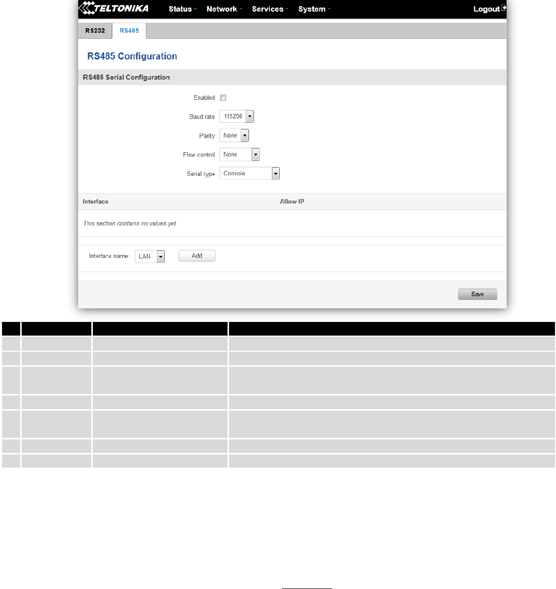
9.5.2 RS485
RS-485 is differential serial data transmission standart for use in long ranges or noisy environments.
Field name
Sample
Explanation
1.
Enabled
Enable/Disable
Check the box to enable the serial port function.
2.
Baud rate
300 / 115200
Selectthe communication speed of the serial interface.
3.
Parity
None / Odd / Even
Selectthe parity bit setting used for error detection during data
transfer.
4.
Flow control
None / RTS- CTS / Xon-Xoff
Specifies what kind of characters to use for flow control
5.
Serial type
Console / Over IP / Modem
/ Modbus Gateway
Specifies function of serial interface
6.
Interface
LAN/ WAN/ VPN
Interface used for connection
7.
Allow IP
192.168.1.102
Allow IP connecting to server
9.5.2.1 Maximum data rate vs. transmission line length
RS-485 standart can be used for network lengths up to 1200 meters, but the maximum usable data rate decreases
as the transmission length increases. Device operating at maximum data rate( 10Mbps) is limited to transmission length
of about 12 meters, while the 100kbps data rate can achieve a distance up to 1200 meters.A rough relation between
maximum transmission length and data rate can be calculated using approximation:
Where Lmax is maximum transmission length in meters and DR is maximum data rate in bits per second.
Twisted pair is the prefered cable for RS-485 networks. Twisted pair cables picks up noise and other
electromagnetically induced voltages as common mode signals, which are rejected by the differential receivers.
94
9.5.2.2 Cable type
Recomended cable parameters:
Parameter
Value
Cable Type
22-24 AWG, 2 – pair (used for full-duplex networks ) or 1-pair (used for half
duplex networks). One addtitional wire for ground connection is needed.
Characteristic cable Impedance
120 Ω @ 1MHz
Capacitance (conductor to conductor)
36 pF/m
Propagation Velocity
78% (1.3 ns/ft)
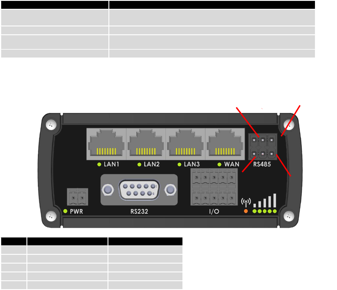
9.5.2.3 RS485 connector pin-out
Name
Description
Type
D_P
Driver positive signal
Differential Output
D_N
Driver negative signal
Differential Output
R_P
Receiver positive signal
Differential input
R_N
Receiver negative signal
Differential input
Ground
Device ground
Differential Output
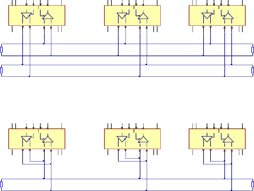
9.5.2.4 2-Wire and 4-Wire Networks
Below is an example of 4- wire network electrical connection. There are 3 devices shown in the example. One of
the devices is master and other two- slaves. Termination resistors are placed at each cable end. Four-wire networks
consists of one „master“ with its transmitter connected to each of the “slave” receivers on one twisted pair. The“slave”
transmitters are all connected to the “master” receiver on a second twisted pair.
D_P
R_P
N/C
D_N
R_N
Ground
95
Example 2-wire network electrical connection: to enable 2-wire RS-485 configuration in Teltonika router, you
need to connect D_P to R_P and D_N to R_N at the device RS-485 socket. Termination resistors are placed at each cable
end.
9.5.2.5 Termination
When to use (place jumper)
Termination resistor, equal in resistance to cable characteristic impedance, must be connected at each end of the
cable to reduce reflection and ringing of the signals when the cable lengths get relatively long. Rise time of the RUT9XX
RS-485 driver is about 5ns, so maximum unterminated cable length is about 12cm. As transmission line cables will be
always longer than 12 cm, termination is mandatory all the time if RUT9xx is located at the end of the cable.
When not to use (remove jumper)
If your RS-485 consists of more than two devices and RUT9xx router is located not on the end of the line, for
example at the middle, RUT9xx termination resistor needs to be disabled.In this case, please termination at other
devices which are situated at the ends of the line.
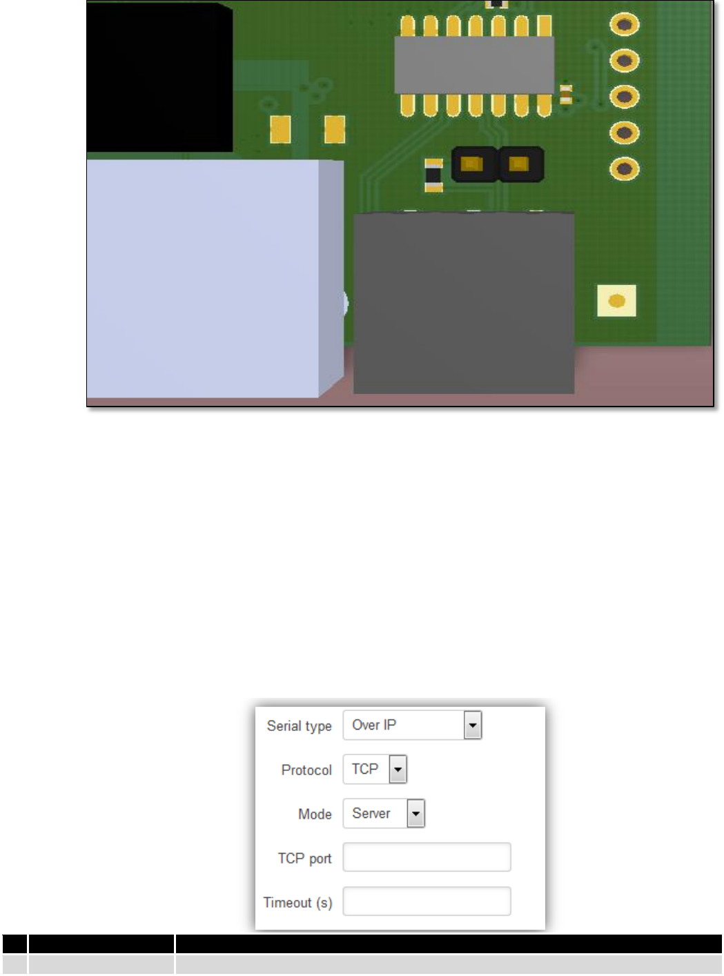
How to enable termination
120 Ω termination resistor is included on RUT9xx PCB and can be enabled by shorting contacts(shown in the
picture below), placing 2.54mm pitch jumper:
V CC
13
RO 2
DI5
GND 6
Y
9
Z
10
B
11
A
12 R
D
GND 7
RE 3
DE4
NC1
NC
8
V CC
14
V CC
13
RO 2
DI5
GND 6
Y
9
Z
10
B
11
A
12 R
D
GND 7
RE 3
DE4
NC1
NC
8
V CC
14
V CC
13
RO 2
DI5
GND 6
Y
9
Z
10
B
11
A
12 R
D
GND 7
RE 3
DE4
NC1
NC
8
V CC
14
D+
D-
R-
R+
Rt
Rt
Rt
Rt
D+
D-
R-
R+
D+
D-
R-
R+
V CC
13
RO 2
DI5
GND 6
Y
9
Z
10
B
11
A
12 R
D
G N D 7
RE 3
DE4
NC1
NC
8
V CC
14
V CC
13
RO 2
DI5
GND 6
Y
9
Z
10
B
11
A
12 R
D
GND 7
RE 3
DE4
NC1
NC
8
V CC
14
V CC
13
RO 2
DI5
GND 6
Y
9
Z
10
B
11
A
12 R
D
GND 7
RE 3
DE4
NC1
NC
8
V CC
14
D+
D-
R-
R+
Rt Rt
D+
D-
R-
R+
D+
D-
R-
R+
96
9.5.2.6 Number of devices in RS-485 Network
One RUT9xx RS-485 driver is capable of driving maximum 32 receivers, provided that receiver input impedance is
12kΩ. If receiver impedances are higher, maximum number of receivers in network increases. Any combination of
receiver types can be connected together, provided their parallel impedance does not exceed RLoad> 375Ω.
9.5.3 Modes of different serial types in RS232 and RS485
9.5.3.1 Console mode
In this mode the serial interface set up as Linux console of the device. It can be used for debug purposes, to get
the status of the device or to control it.
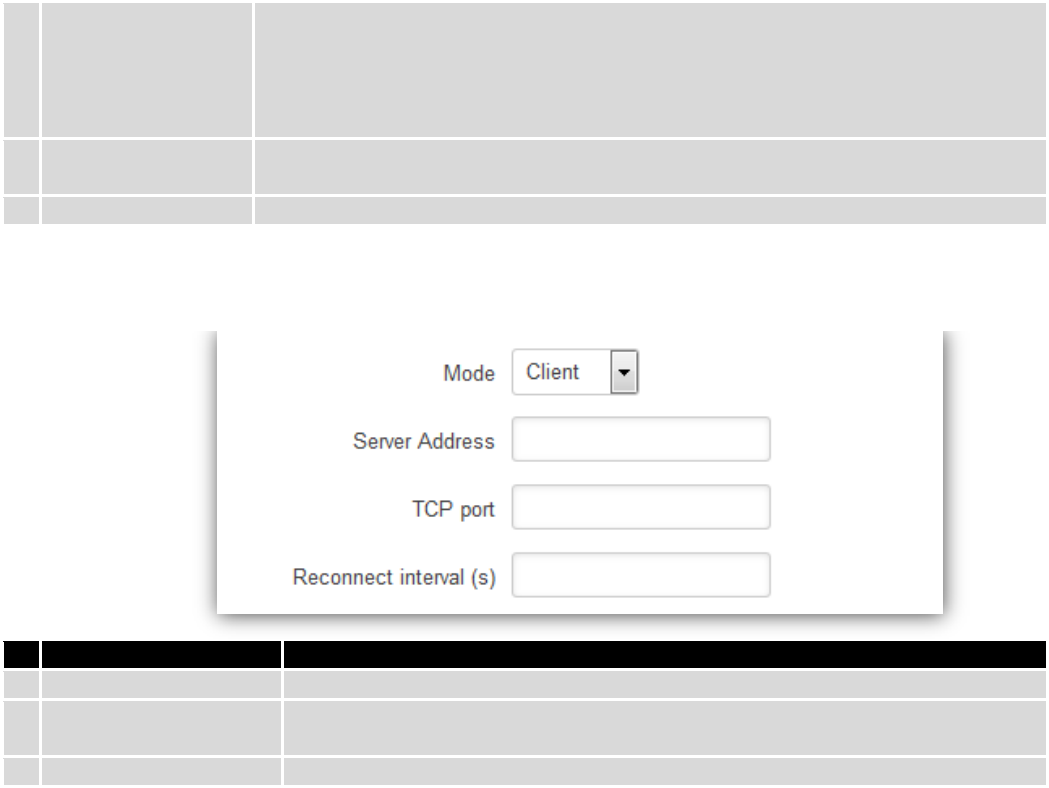
9.5.3.2 Over IP mode
In this mode the router provides connection to TPC/IP network for the devices connected via serial interfaces.
Field name
Explanation
1.
Protocol
Select which protocol to use for data transmission
97
2.
Mode
Select mode to apply for router.
Server - wait for incoming connection.
Client - initiate the connection.
Bidirect – On default acts like client, but at the same time waits for incoming
connections.
3.
TCP port
Specify port number that will be used to listen for incoming connections (Server) or
port of the remote server (Client)
4.
Timeout (s)
Disconnect client if not active connection
Client:
Field name
Explanation
1.
Server Address
Specify server address which client have to connect
2.
TCP port
Specify port number that will be used to listen for incoming connections (Server)
or port of the remote server (Client)
3.
Reconnect intervals (s)
Specify intervals connection to server if it fails
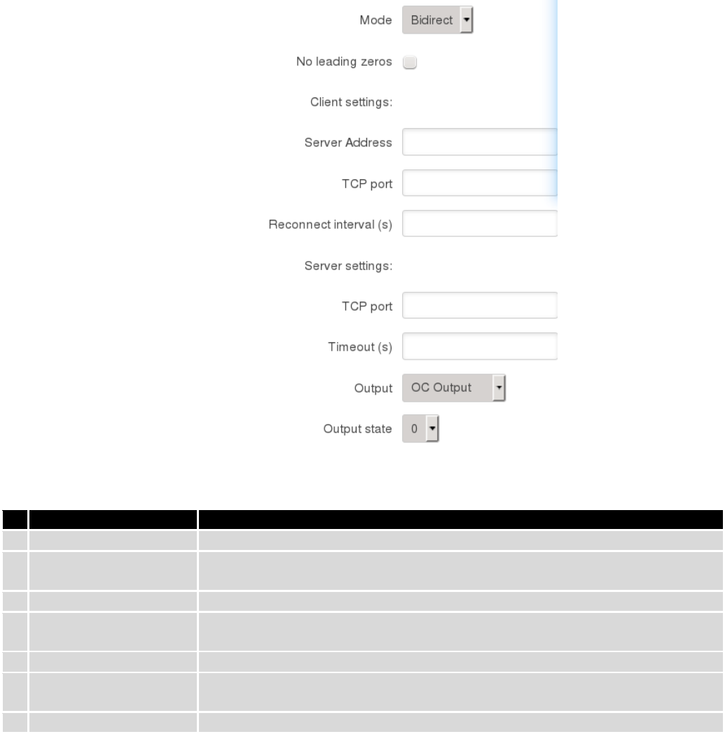
Bidirect:
98
Bidirect mode allows bi-directional communication through serial interface. In default state application acts like
client, but at the same time, listens to any incoming connections on dedicated port. When there is connection incoming
the application drops current connection to remote server and acts like a server to the new connection. This triggers
configured output change, which can be used to inform any auxiliary devices about connection status change. When the
client connection is terminated application returns to default mode and continues as a client to remote server.
Field name
Explanation
1.
Server Address
Specify server address which client will connect to
2.
TCP port
Specify port number to connect to (Client settings) or listen for incoming
connections (Server settings)
3.
Reconnect intervals (s)
Specify time intervals for reconnection to server if connection fails
4.
TCP port
Specify port number that will be used to listen for incoming connections (Server
settings) or port of the remote server to connect (Client settings)
5.
Timeout (s)
Timeout period for inactive client connections
6.
Output
Output (OC or Relay) to indicate that application switched from client (default) to
server state
7.
Output state
Output state value (0 or 1), when application reverts to server mode
9.5.3.3 Modem mode
In this mode the router imitates dial-up modem. Connection to TCP/IP network can be established using AT
commands. The connection can be initiated by the device connected via serial interface with ATD command:
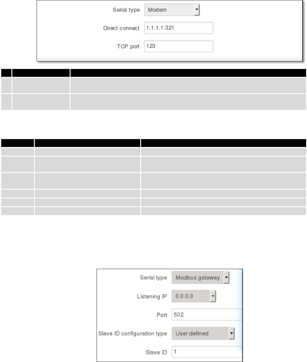
99
ATD<host>:<port>. If Direct connect settings are specified the connection to the server is always active. Data mode can
be entered by issuing ATD command. Incoming connection is indicated by sending RING to the serial interface.
Field name
Explanation
1.
Direct connect
Enter hostname:port to maintain constant connection to specified host. Leave empty to
use ATD command to initiate connection.
2.
TCP port
Specify TCP port number that will be used to listen for incoming connections. Leave it
empty to disable incoming connections.
This is the AT command set used in Modem mode of the serial interfaces:
Command
Description
Usage
A
Answer incoming call
To answer incoming connection: ATA
D
Dial a number
To initiate data connection: ATD<host>:<port>
To enter data mode with Direct connect settings: ATD
E
Local echo
Turn local echo on: ATE1
Turn local echo off: ATE0
H
Hang up current call
To end data connection: ATH
O
Return to data mode
To return to data mode from command mode: ATO
Z
Reset to default configuration
To reset the modem to default configuration: ATZ
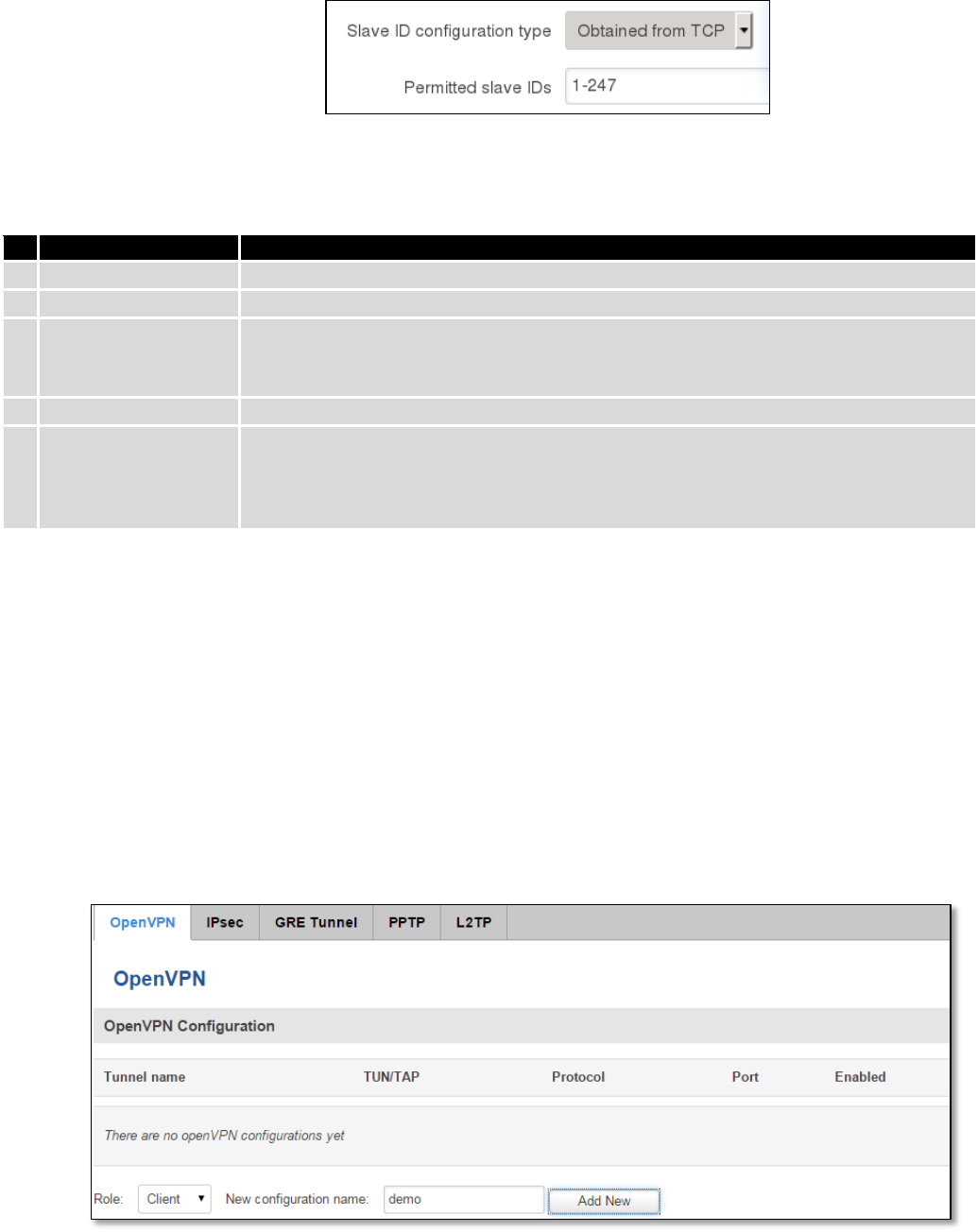
9.5.3.4 Modbus Gateway mode
This mode allows redirecting TCP data coming to specified port to RTU specified by slave ID. As we can see later,
slave ID can be specified by the user or can be obtained directly from the Modbus header.
100
Field name
Explanation
1.
Listening IP
IP address on which Modbus gateway should wait for incoming connections
2.
Port
Port number for Modbus Gateway
3.
Slave ID
configuration type
There are two options available for this parameter. “User defined” redirects all data
to slave ID specified by the parameter “Slave ID”. “Obtain from TCP” redirects data
to slave ID according to Modbus TCP header
4.
Slave ID
ID of the Modbus TCP slave device which is connected to the router
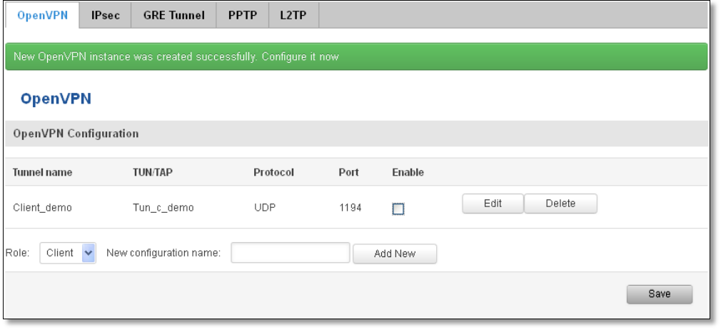
5.
Permitted slave IDs
Allows specifying the list of permitted slave IDs for redirecting of the Modbus TCP
data. Individual values can be separated using ‘,’ (comma), while the range can be
specified using ‘-‘ (hyphen), e.g., 1,2,4-6. All other slave IDs not listed here are
ignored.
9.6 VPN
9.6.1 OpenVPN
VPN (Virtual Private Network) is a method for secure data transfer through unsafe public network. This section
explains how to configure OpenVPN, which is implementation of VPN supported by the RUT9 router.
A picture below demonstrates default OpenVPN configurations list, which is empty, so you have to define a new
configuration to establish any sort of OpenVPN connection. To create it, enter desired configuration name in “New
configuration name” field, select device role from “Role” drop down list. For example, to create an OpenVPN client with
configuration name demo, select client role, name it “demo” and press “Add New” button as shown in the following
picture.
101
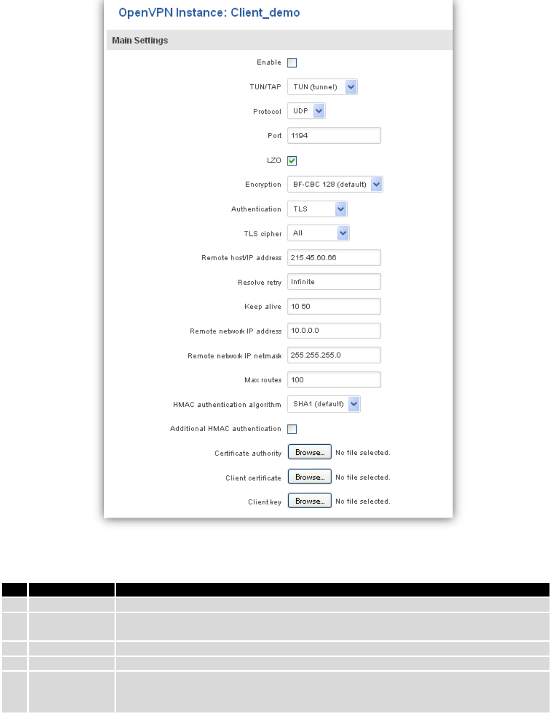
To see at specific configuration settings press “edit” button located in newly created configuration entry. A new
page with detailed configuration appears, as shown in the picture below (TLS client example).
102
There can be multiple server/client instances.
You can set custom settings here according to your VPN needs. Below is summary of parameters available to set:
Field name
Explanation
1.
Enabled
Switches configuration on and off. This must be selected to make configuration active.
2.
TUN/TAP
Selects virtual VPN interface type. TUN is most often used in typical IP-level VPN connections,
however, TAP is required to some Ethernet bridging configurations.
3.
Protocol
Defines a transport protocol used by connection. You can choose here between TCP and UDP.
4.
Port
Defines TCP or UDP port number (make sure, that this port allowed by firewall).
5.
LZO
This setting enables LZO compression. With LZO compression, your VPN connection will
generate less network traffic; however, this means higher router CPU loads. Use it carefully
with high rate traffic or low CPU resources.

103
6.
Encryption
Selects Packet encryption algorithm.
7.
Authentication
Sets authentication mode, used to secure data sessions. Two possibilities you have here:
“Static key” means, that OpenVPN client and server will use the same secret key, which must
be uploaded to the router using “Static pre-shared key” option. “TLS” authentication mode
uses X.509 type certificates. Depending on your selected OpenVPN mode (client or server)
you have to upload these certificates to the router:
For client: Certificate Authority (CA), Client certificate, Client key.
For server: Certificate Authority (CA), Server certificate, Server key and Diffie-Hellman (DH)
certificate used to key exchange through unsafe data networks.
All mention certificates can be generated using OpenVPN or Open SSL utilities on any type
host machine. Certificate generation and theory is out of scope of this user manual.
8.
TLS cipher
Packet encryption algorithm (cipher)
9.
Remote host/IP
address
IP address of OpenVPN server (applicable only for client configuration).
10.
Resolve Retry
Sets time in seconds to try resolving server hostname periodically in case of first resolve
failure before generating service exception.
11.
Keep alive
Defines two time intervals: one is used to periodically send ICMP request to OpenVPN server,
and another one defines a time window, which is used to restart OpenVPN service, if no ICPM
request is received during the window time slice. Example Keep Alive “10 60”
12.
Remote network
IP address
IP address of remote network, an actual LAN network behind another VPN endpoint.
13.
Remote network
IP netmask
Subnet mask of remote network, an actual LAN network behind another VPN endpoint.
14.
Max routes
Allow a maximum number of routes to be pulled from an OpenVPN server
15.
HMAC
authentication
algorithm
Sets HMAC authentication algorithm
16.
Additional
HMAC
authentication
Add an additional layer of HMAC authentication on top of the TLS control channel to protect
against DoS attacks
17.
Certificate
authority
Certificate authority is an entity that issues digital certificates. A digital certificate certifies the
ownership of a public key by the named subject of the certificate.
18.
Client certificate
Client certificate is a type of digital certificate that is used by client systems to make
authenticated requests to a remote server. Client certificates play a key role in many mutual
authentication designs, providing strong assurances of a requester's identity.
19.
Client key
Authenticating the client to the server and establishing precisely who they are
After setting any of these parameters press “Save” button. Some of selected parameters will be shown in the
configuration list table. You should also be aware of the fact that router will launch separate OpenVPN service for every
configuration entry (if it is defined as active, of course) so the router has ability to act as server and client at the same
time.
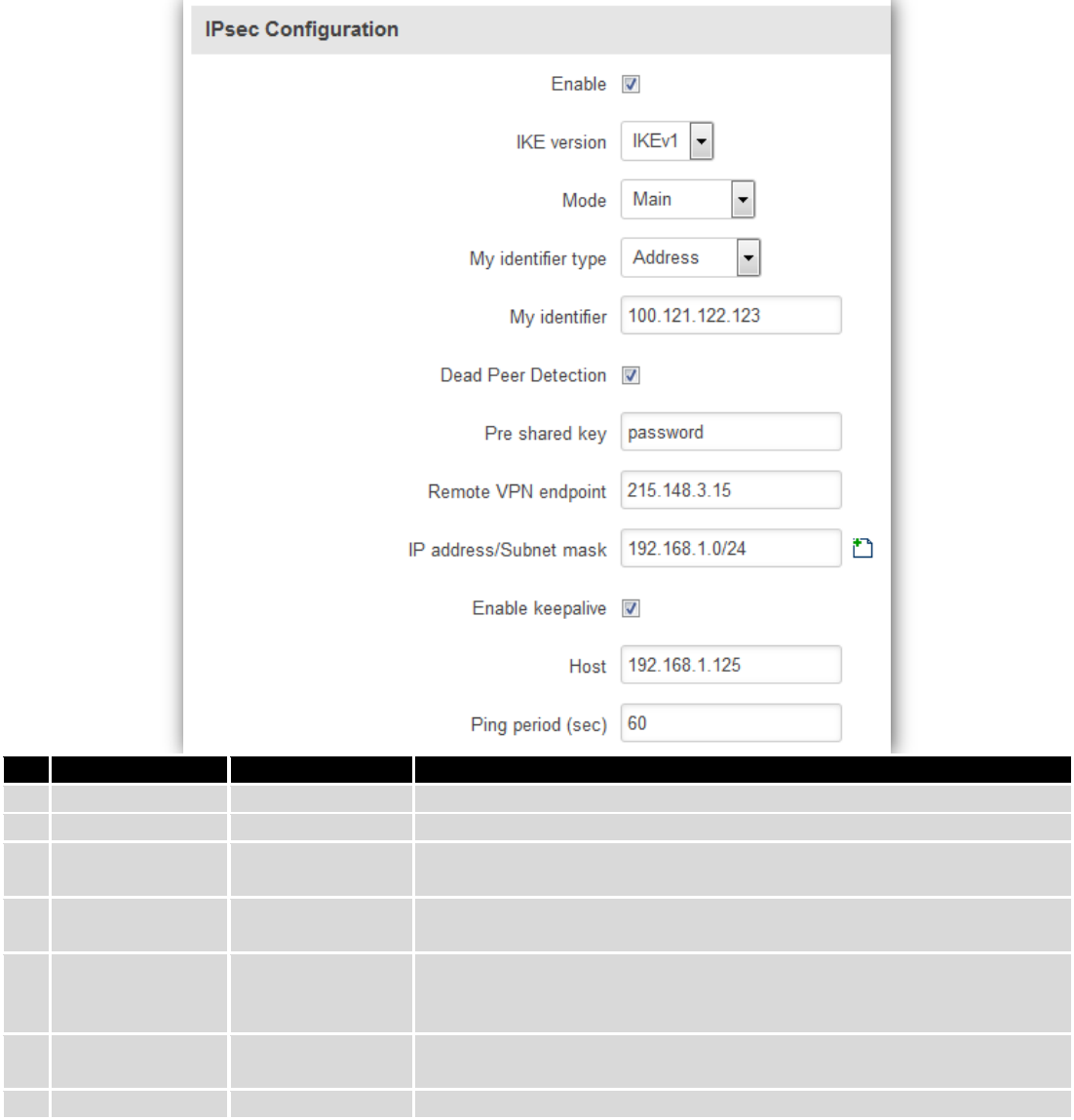
9.6.2 IPSec
The IPsec protocol client enables the router to establish a secure connection to an IPsec peer via the Internet.
IPsec is supported in two modes - transport and tunnel. Transport mode creates secure point to point channel between
two hosts. Tunnel mode can be used to build a secure connection between two remote LANs serving as a VPN solution.
104
IPsec system maintains two databases: Security Policy Database (SPD) which defines whether to apply IPsec to a
packet or not and specify which/how IPsec-SA is applied and Security Association Database (SAD), which contain Key of
each IPsec-SA.
The establishment of the Security Association (IPsec-SA) between two peers is needed for IPsec communication. It
can be done by using manual or automated configuration.
Note: router starts establishing tunnel when data from router to remote site over tunnel is sent. For automatic
tunnel establishment used tunnel Keep Alive feature.
Field name
Value
Explanation
1.
Enable
Enabled/Disabled
Check box to enable IPSec.
2.
IKE version
IKEv1 or IKEv2
Method of key exchange
3.
Mode
“Main” or
“Aggressive”
ISAKMP (Internet Security Association and Key Management Protocol)
phase 1 exchange mode
4.
My identifier type
Address, FQDN,
User FQDN
Choose one accordingly to your IPSec configuration
5.
My identifier
Set the device identifier for IPSec tunnel.
In case RUT has Private IP, its identifier should be its own LAN network
address. In this way, the Road Warrior approach is possible.
6.
Dead Peer
Detection
Enabled/Disabled
The values clear, hold and restart all active DPD
7.
Pre shared key
A shared password to authenticate between the peer
105
8.
Remote VPN
endpoint
Domain name or IP address. Leave empty or any
9.
IP
address/Subnet
mask
Remote network secure group IP address and mask used to determine to
what subnet an IP address belongs to. Range [0-32]. IP should differ from
device LAN IP
10.
Enable keep alive
Enabled/Disabled
Enable tunnel keep alive function
11.
Host
A host address to which ICMP (Internet Control Message Protocol) echo
requests will be send
12.
Ping period (sec)
Send ICMP echo request every x seconds. Range [0-999999]
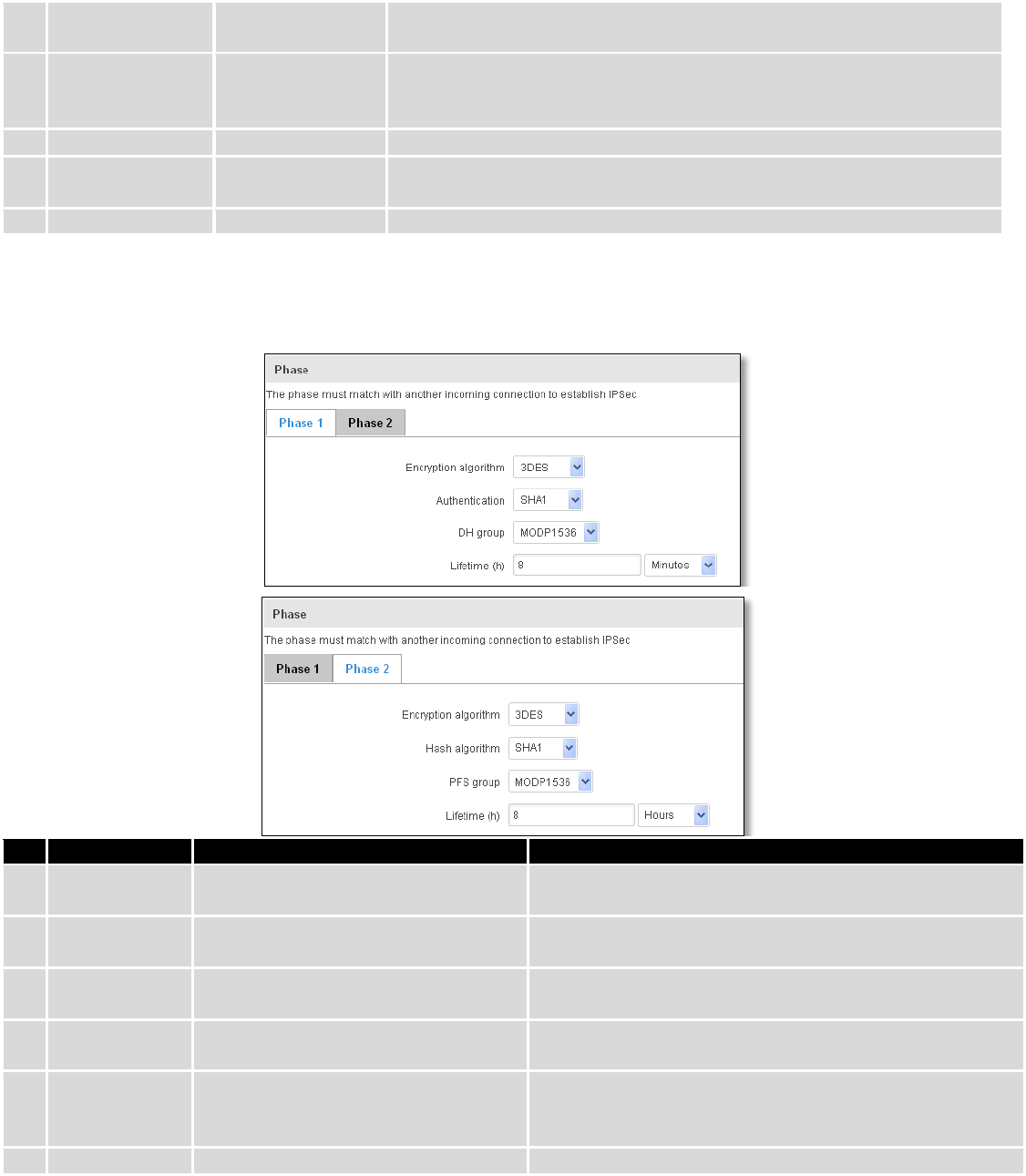
Phase 1 and Phase 2 must be configured accordingly to the IPSec server configuration, thus algorithms,
authentication and lifetimes of each phase must be identical.
Field name
Value
Explanation
1.
Encryption
algorithm
DES, 3DES, AES 128, AES 192, AES256
The encryption algorithm must match with another
incoming connection to establish IPSec
2.
Authentication
MD5, SHA1, SHA256, SHA384, SHA512
The authentication algorithm must match with another
incoming connection to establish IPSec
3.
Hash algorthm
MD5, SHA1, SHA256, SHA384, SHA512
The hash algorithm must match with another incoming
connection to establish IPSec
4.
DH group
MODP768, MODP1024, MODP1536,
MODP2048, MODP3072, MODP4096
The DH (Diffie-Helman) group must with another
incoming connection to establish IPSec
4.
PFS group
MODP768, MODP1024, MODP1536,
MODP2048, MODP3072, MODP4096,
No PFS
The PFS (Perfect Forward Secrecy) group must match with
another incoming connection to establish IPSec
5.
Lifetime
Hours, Minutes, Seconds
The time duration for phase
106
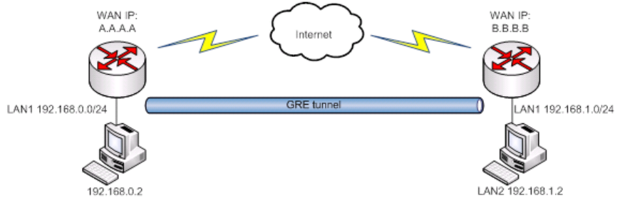
9.6.3 GRE Tunnel
GRE (Generic Routing Encapsulation RFC2784) is a solution for tunneling RFC1812 private address-space traffic
over an intermediate TCP/IP network such as the Internet. GRE tunneling does not use encryption it simply encapsulates
data and sends it over the WAN.
In the example network diagram two distant networks LAN1 and LAN2 are connected.
To create GRE tunnel the user must know the following parameters:
1. Source and destination IP addresses.
2. Tunnel local IP address
3. Distant network IP address and Subnet mask.
107
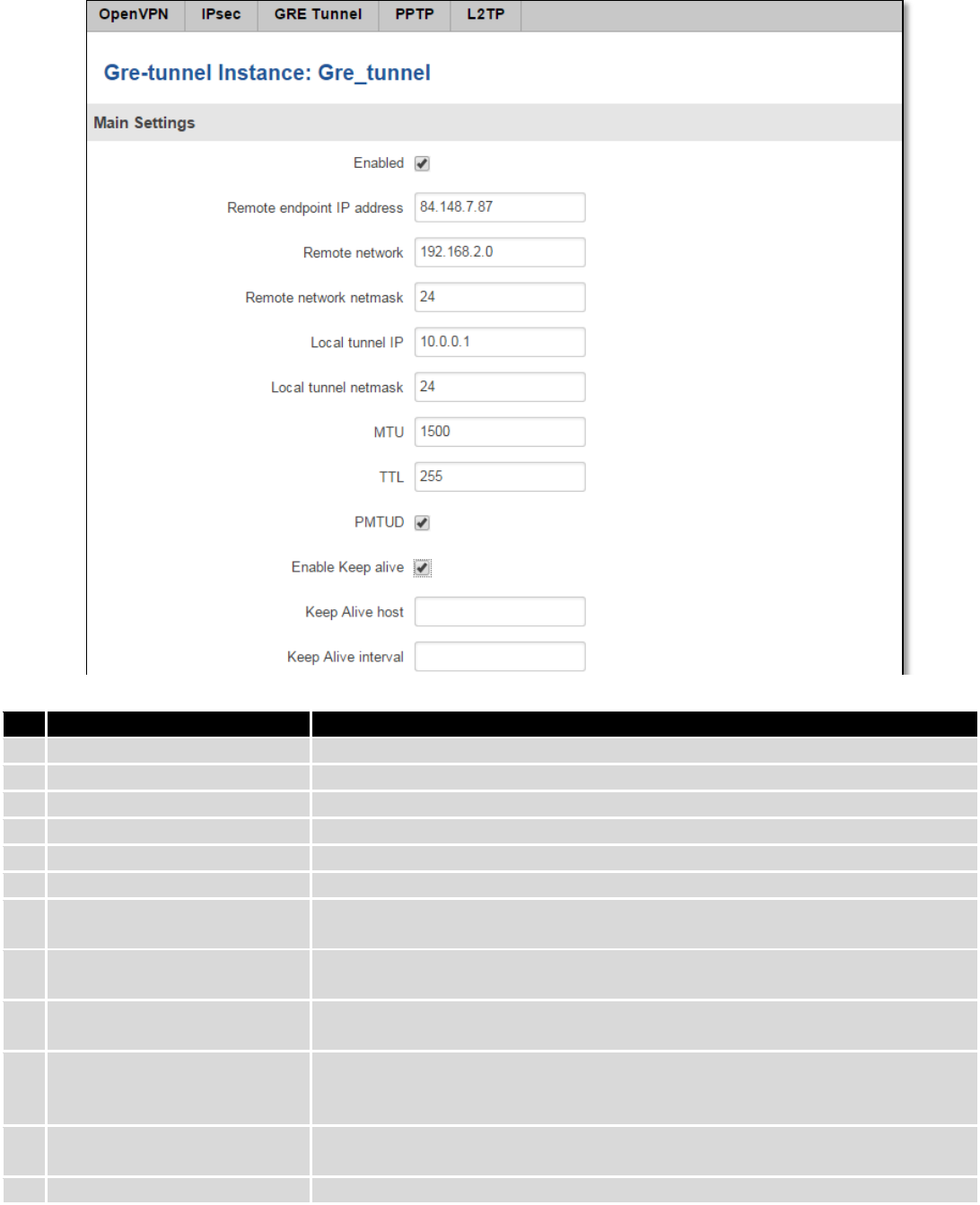
Field name
Explanation
1.
Enabled
Check the box to enable the GRE Tunnel function.
2.
Remote endpoint IP address
Specify remote WAN IP address.
3.
Remote network
IP address of LAN network on the remote device.
4.
Remote network netmask
Network of LAN network on the remote device. Range [0-32].
5.
Local tunnel IP
Local virtual IP address. Cannot be in the same subnet as LAN network.
6.
Local tunnel netmask
Network of local virtual IP address. Range [0-32]
7.
MTU
Specify the maximum transmission unit (MTU) of a communications protocol of
a layer in bytes.
8.
TTL
Specify the fixed time-to-live (TTL) value on tunneled packets [0-255]. The 0 is a
special value meaning that packets inherit the TTL value.
9.
PMTUD
Check the box to enable the Path Maximum Transmission Unit Discovery
(PMTUD) status on this tunnel.
10.
Enable Keep alive
It gives the ability for one side to originate and receive keep alive packets to and
from a remote router even if the remote router does not support GRE keep
alive.
11.
Keep Alive host
Keep Alive host IP address. Preferably IP address which belongs to the LAN
network on the remote device.
12.
Keep Alive interval
Time interval for Keep Alive. Range [0 - 255].
108
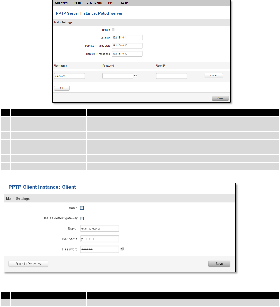
9.6.4 PPTP
Point-to-Point Tunneling Protocol (PPTP) is a protocol (set of communication rules) that allows corporations to
extend their own corporate network through private "tunnels" over the public Internet. Effectively, a corporation uses a
wide-area network as a single large local area network. A company no longer needs to lease its own lines for wide-area
communication but can securely use the public networks. This kind of interconnection is known as a virtual private
network (VPN).
Field name
Explanation
1.
Enable
Check the box to enable the PPTP function.
2.
Local IP
IP Address of this device (RUT)
3.
Remote IP range begin
IP address leases beginning
4.
Remote IP range end
IP address leases end
5.
Username
Username to connect to PPTP (this) server
6.
Password
Password to connect to PPTP server
7.
User IP
Users IP address
Field name
Explanation
1.
Enable
Enable current configuration
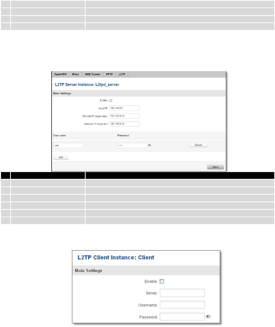
109
2.
Use as default gateway
Use this PPTP instance as default gateway
3.
Server
The server IP address or hostname
4.
Username
The user name for authorization with the server
5.
Password
The password for authorization with the server
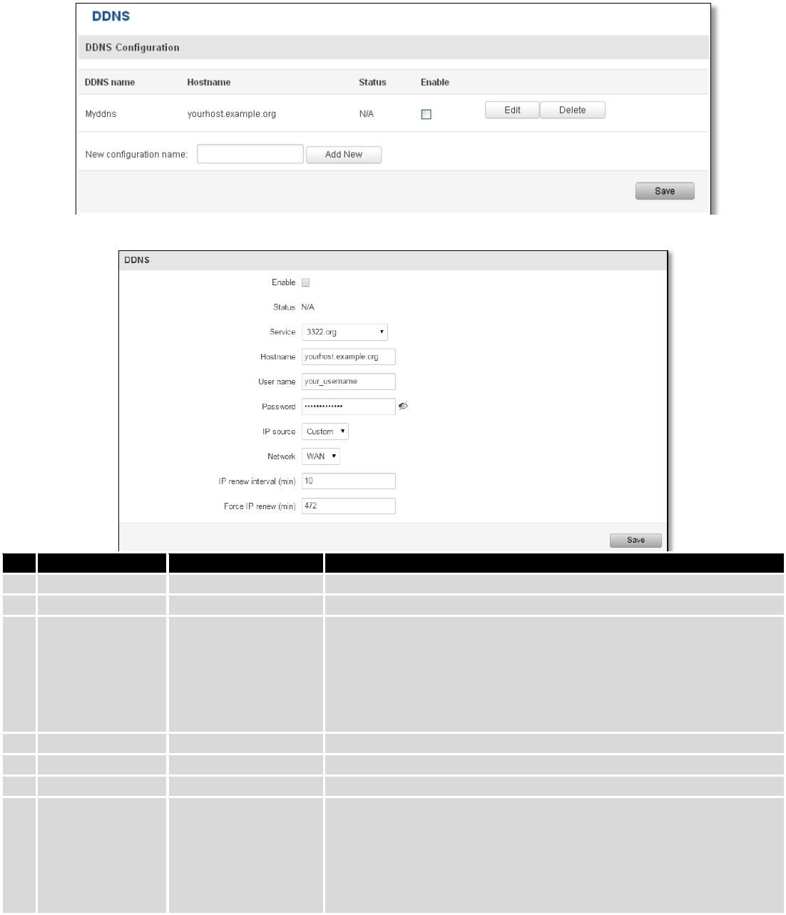
9.6.5 L2TP
Allows setting up a L2TP server or client. Below is L2TP server configuration example.
Field name
Explanation
1.
Enable
Check the box to enable the L2TP Tunnel function.
2.
Local IP
IP Address of this device (RUT)
3.
Remote IP range begin
IP address leases beginning
4.
Remote IP range end
IP address leases end
5.
Username
Username to connect to L2TP (this) server
6.
Password
Password to connect to L2TP server
Client configuration is even simpler, which requires only Servers IP, Username and Password.
9.7 Dynamic DNS
Dynamic DNS (DDNS) is a domain name service allowing to link dynamic IP addresses to static hostname.
To start using this feature firstly you should register to DDNS service provider (example list is given in description).
110
You are provided with add/delete buttons to manage and use different DDNS configurations at the same time!
You can configure many different DDNS Hostnames in the main DDNS Configuration section.
To edit your selected configuration, hit Edit.
Field name
Value
Explanation
1.
Enable
Enable/Disable
Enables current DDNS configuration.
2.
Status
Timestamp of the last IP check or update.
3.
Service
1. dydns.org
2. 3322.org
3. no-ip.com
4. easydns.com
5. zoneedit.com
Your dynamic DNS service provider selected from the list.
In case your DDNS provider is not present from the ones provided,
please feel free to use "custom" and add hostname of the update
URL.
4.
Hostname
yourhost.example.org
Domain name which will be linked with dynamic IP address.
5.
Username
your_username
Name of the user account.
6.
Password
your_password
Password of the user account.
7.
IP Source
Public
Private
Custom
This option allows you to select specific RUT interface, and then send
the IP address of that interface to DDNS server. So if, for example,
your RUT has Private IP (i.e. 10.140.56.57) on its WAN (3G interface),
then you can send this exact IP to DDNS server by selecting "Private",
or by selecting "Custom" and "WAN" interface. The DDNS server will
then resolve hostname queries to this specific IP.
111
8.
Network
WAN
Source network
9.
IP renew interval
(min)
10 (minutes)
Time interval (in minutes) to check if the IP address of the device
have changed.
10.
Force IP renew
472 (minutes)
Time interval (in minutes) to force IP address renew.
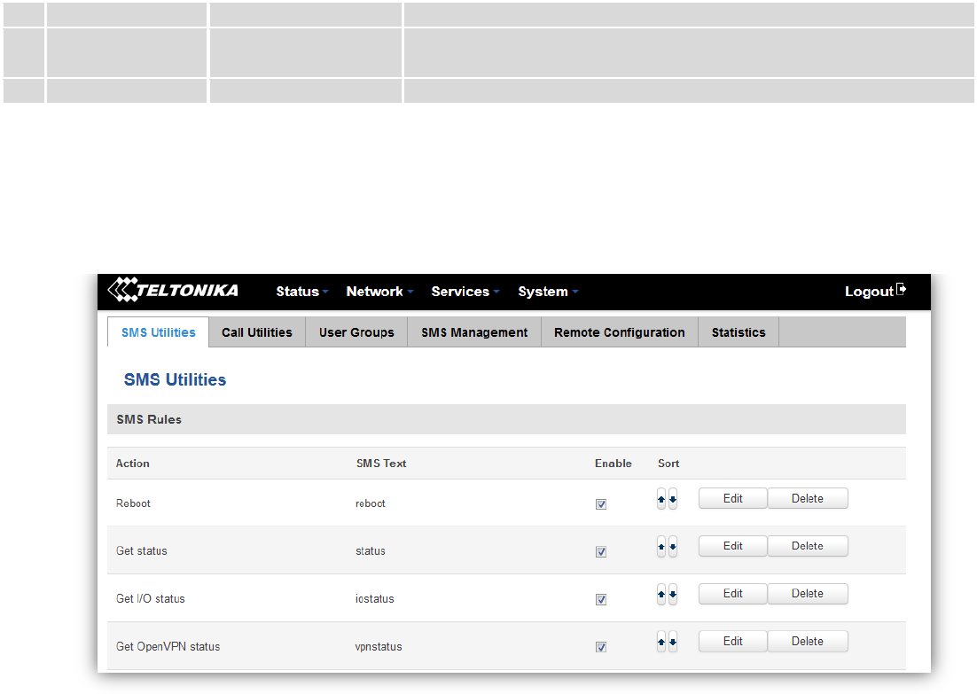
9.8 SMS Utilities
RUT955 has extensive amount of various SMS Utilities. These are subdivided into 6 sections: SMS Utilities, Call
Utilities, User Groups, SMS Management, Remote Configuration and Statistics.
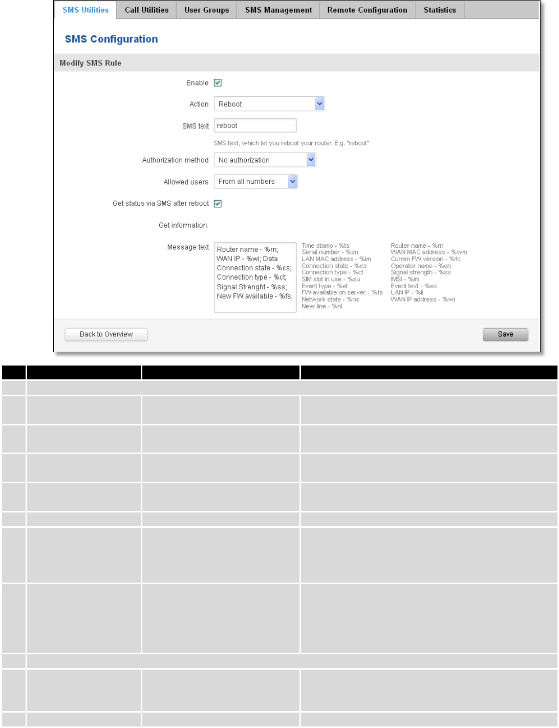
9.8.1 SMS Utilities
All configuration options are listed below:
- Reboot
- Get status
- Get I/O status
- Switch output on / off
- Get OpenVPN status
- Switch WiFi on / off
- Switch mobile data on / off
- Change mobile data settings
- Get list of profiles
- Change profile
- Manage OpenVPN
- SSh access control
- Web access control
- Restore to default
- Force SIM switch
- GPS coordinates
- GPS on / off
- FW upgrade from server
- Config update from server
- Switch monitoring on / off
- Monitoring status
You can choose your SMS Keyword (text to be sent) and authorized phone number in the main menu. You can
edit each created rule by hitting Edit button.
112
Field name
Explanation
Notes
1.
Reboot
Enable
This check box will enable and
disable SMS reboot function.
Allows router restart via SMS.
Action
The action to be performed
when this rule is met.
SMS text
SMS text which will reboot
router.
SMS text can contain letters, numbers, spaces and
special symbols. Capital letters also matters.
Authorization method
What kind of authorization to
use for SIM management.
No authorization, by serial or by router admin
password.
Allowed users
Whitelist of allow users
From all numbers, from group or from single number.
Get status via SMS
after reboot
Check this to recieve
connection status via SMS after
a reboot.
If you select this box, router will send status once it
has rebooted and is operational again.
This is both separate SMS Rule and an option under
SMS Reboot rule.
Message text
Which status information
should be included in SMS:
Data state, Operator,
Connection type, Signal
Strength, Connection State, IP
You can select which status elements to display.
2.
Get status
Enable
Check this to receive
connection status via SMS.
Allows to get router‘s status via SMS. This is both
separate SMS Rule and an option under SMS Reboot
rule.
Action
The action to be performed

113
when this rule is met.
Enable SMS Status
This check box will enable and
disable SMS status function.
SMS status is disabled by default.
SMS text
SMS text which will send
routers status.
SMS text can contain letters, numbers, spaces and
special symbols. Capital letters also matters.
Authorization method
What kind of authorization to
use for SIM management.
No authorization, by serial or by router admin
password.
Allowed users
Whitelist of allow users
From all numbers, from group or from single number.
Message text
Which status information
should be included in SMS:
Data state, Operator,
Connection type, Signal
Strength, Connection State, IP
You can select which status elements to display.
3.
Get OpenVPN status
Enable
This check box will enable and
disable this function.
Allows to get OpenVPN‘s status via SMS.
Action
The action to be performed
when this rule is met.
SMS text
SMS text which will send
OpenVPN status.
SMS text can contain letters, numbers, spaces and
special symbols. Capital letters also matters.
Authorization method
What kind of authorization to
use for SIM management.
No authorization, by serial or by router admin
password.
Allowed users
Whitelist of allow users
From all numbers, from group or from single number.
4.
Switch WiFi On/Off
Enable
This check box will enable and
disable this function.
Allows Wi-Fi control via SMS.
Action
The action to be performed
when this rule is met.
Turn WiFi ON or OFF.
SMS text
SMS text which will turn Wi-Fi
ON/OFF.
SMS text can contain letters, numbers, spaces and
special symbols. Capital letters also matters.
Authorization method
What kind of authorization to
use for SIM management.
No authorization, by serial or by router admin
password.
Allowed users
Whitelist of allow users
From all numbers, from group or from single number.
Write to config
Permanently saves Wi-Fi state.
With this setting enabled, router will keep Wi-Fi state
even after reboot.
If it is not selected, router will revert Wi-Fi state after
reboot.
5.
Switch mobile data on/off
Enable
This check box will enable and
disable this function.
Allows mobile control via SMS.
Action
The action to be performed
when this rule is met.
Turn mobile ON or OFF.
SMS text
SMS text which will turn mobile
data ON/OFF.
SMS text can contain letters, numbers, spaces and
special symbols. Capital letters also matters.
Authorization method
What kind of authorization to
use for SIM management.
No authorization, by serial or by router admin
password.
Allowed users
Whitelist of allow users
From all numbers, from group or from single number.
Write to config
Permanently saves mobile
network state.
With this setting enabled, router will keep mobile
state even after reboot.
If it is not selected, router will revert mobile state

114
after reboot.
6.
Manage OpenVPN
Enable
This check box will enable and
disable this function.
Allows OpenVPN control via SMS.
Action
The action to be performed
when this rule is met.
Turn OpenVPN ON or OFF.
SMS text
Keyword which will turn
OpenVPN ON/OFF.
SMS text can contain letters, numbers, spaces and
special symbols. Capital letters also matters.
After Keyword you have to write OpenVPN name.
Authorization method
What kind of authorization to
use for SIM management.
No authorization, by serial or by router admin
password.
Allowed users
Whitelist of allow users
From all numbers, from group or from single number.
7.
Change mobile data settings
Enable
This check box will enable and
disable this function.
Allows to change mobile settings via SMS.
Action
The action to be performed
when this rule is met.
SMS text
Key word that will precede
actual configuration
parameters.
SMS text can contain letters, numbers, spaces and
special symbols. Capital letters also matters.
Authorization method
What kind of authorization to
use for SIM management.
No authorization, by serial or by router admin
password.
Allowed users
Whitelist of allow users
From all numbers, from group or from single number.
Mobile Settings via SMS parameters:
Parameter
Value(s)
Explanation
1.
apn=
e.g. internet.gprs
Sets APN. i.e: apn=internet.gprs
2.
dialnumber=
e.g. *99***1#
Sets dial number
3.
auth_mode=
none
pap
chap
Sets authentication mode
4.
service=
Auto
4gpreferred
4gonly
3gpreferred
3gonly
2gpreferred
2gonly
You can add as many phone numbers as you need.
Dropdown list with additional rows will show up if you
click on “add” icon at the end of phone number row.
5.
username=
user
Used only if PAP or CHAP authorization is selected
6.
password=
user
Used only if PAP or CHAP authorization is selected
All Mobile settings can be changed in one SMS. Between each <parameter=value> pair a space symbol is
necessary.
Example: cellular apn=internet.gprs dialnumber=*99***1#auth_mode=pap service=3gonly username=user
password=user
Important Notes:
3G settings must be configured correctly. If SIM card has PIN number you must enter it at “Network” > “3G”
settings. Otherwise SMS reboot function will not work.

115
Sender phone number must contain country code. You can check sender phone number format by reading
the details of old SMS text massages you receiving usually.
Field name
Explanation
Notes
8.
Get list of profiles
Enable
This check box will enable and
disable this function.
Allows to get list of profiles via SMS.
Action
The action to be performed
when this rule is met.
SMS text
SMS text which will send list of
profiles.
SMS text can contain letters, numbers, spaces and
special symbols. Capital letters also matters.
Authorization method
What kind of authorization to
use for SIM management.
No authorization, by serial or by router admin
password.
Allowed users
Whitelist of allow users
From all numbers, from group or from single number.
9.
Change profile
Enable
This check box will enable and
disable this function.
Allows profile change via SMS.
Action
The action to be performed
when this rule is met.
SMS text
Keyword which will change
active profile.
SMS text can contain letters, numbers, spaces and
special symbols. Capital letters also matters.
After Keyword you have to write profile name.
Authorization method
What kind of authorization to
use for SIM management.
No authorization, by serial or by router admin
password.
Allowed users
Whitelist of allow users
From all numbers, from group or from single number.
10.
SSH access Control
Enable
This check box will enable and
disable this function.
Allows SSH access control via SMS.
Action
The action to be performed
when this rule is met.
SMS text
SMS text which will turn SSH
access ON/OFF.
SMS text can contain letters, numbers, spaces and
special symbols. Capital letters also matters.
Authorization method
What kind of authorization to
use for SIM management.
No authorization, by serial or by router admin
password.
Allowed users
Whitelist of allow users
From all numbers, from group or from single number.
Enable SSH access
Enable this to reach router via
SSH from LAN (Local Area
Network).
If this box is selected, SMS will enable SSH access from
LAN. If this box is not selected, SMS will disable SSH
access from LAN.
Enable remote SSH
access
Enable this to reach router via
SSH from WAN (Wide Area
Network).
If this box is selected, SMS will enable SSH access from
WAN. If this box is not selected, SMS will disable SSH
access from WAN.
11.
Web access Control
Enable
This check box will enable and
disable this function.
Allows Web access control via SMS.
Action
The action to be performed
when this rule is met.
SMS text
SMS text which will turn Web
access ON/OFF.
SMS text can contain letters, numbers, spaces and
special symbols. Capital letters also matters.
Authorization method
What kind of authorization to
No authorization, by serial or by router admin

116
use for SIM management.
password.
Allowed users
Whitelist of allow users
From all numbers, from group or from single number.
Enable HTTP access
Enable this to reach router via
HTTP from LAN (Local Area
Network).
If this box is selected, SMS will enable HTTP access
from LAN. If this box is not selected, SMS will disable
HTTP access from LAN.
Enable remote HTTP
access
Enable this to reach router via
HTTP from WAN (Wide Area
Network).
If this box is selected, SMS will enable HTTP access
from WAN. If this box is not selected, SMS will disable
HTTP access from WAN.
Enable remote HTTPS
access
Enable this to reach router via
HTTPS from WAN (Wide Area
Network).
If this box is selected, SMS will enable HTTPS access
from WAN. If this box is not selected, SMS will disable
HTTPS access from WAN.
12.
Restore to default
Enable
This check box will enable and
disable this function.
Allows to restore router to default settings via SMS.
Action
The action to be performed
when this rule is met.
Router will reboot after this rule is executed.
SMS text
SMS text which will turn Wi-Fi
ON/OFF.
SMS text can contain letters, numbers, spaces and
special symbols. Capital letters also matters.
Authorization method
What kind of authorization to
use for SIM management.
No authorization, by serial or by router admin
password.
Allowed users
Whitelist of allow users
From all numbers, from group or from single number.
13.
Force switch SIM
Enable
This check box will enable and
disable this function.
Allows SIM switch via SMS.
Action
The action to be performed
when this rule is met.
SMS text
SMS text which will change
active SIM card to another one.
SMS text can contain letters, numbers, spaces and
special symbols. Capital letters also matters.
Authorization method
What kind of authorization to
use for SIM management.
No authorization, by serial or by router admin
password.
Allowed users
Whitelist of allow users
From all numbers, from group or from single number.
Sender phone number
Phone number of person who
can receive router status via
SMS message.
You can add as many phone numbers as you need.
Dropdown list with additional rows will show up if you
click on “add” icon at the end of phone number row.
14.
Force FW upgrade from server
Enable
This check box will enable and
disable this function.
Allows to upgrade router‘s FW via SMS.
Action
The action to be performed
when this rule is met.
Router will reboot after this rule is executed.
SMS text
SMS text which will force router
to upgrade firmware from
server.
SMS text can contain letters, numbers, spaces and
special symbols. Capital letters also matters.
Authorization method
What kind of authorization to
use for SIM management.
No authorization, by serial or by router admin
password.
Allowed users
Whitelist of allow users
From all numbers, from group or from single number.
15.
Force Config update from server
Enable
This check box will enable and
disable this function.
Allows to upgrade router‘s Config via SMS.
Action
The action to be performed
when this rule is met.
Router will reboot after this rule is executed.

117
SMS text
SMS text which will force router
to upgrade configuration from
server.
SMS text can contain letters, numbers, spaces and
special symbols. Capital letters also matters.
Authorization method
What kind of authorization to
use for SIM management.
No authorization, by serial or by router admin
password.
Allowed users
Whitelist of allow users
From all numbers, from group or from single number.
16.
Switch monitoring on/off
Enable
This check box will enable and
disable this function.
Allows monitoring control via SMS.
Action
The action to be performed
when this rule is met.
Turn monitoring ON or OFF.
SMS text
SMS text which will turn
monitoring ON/OFF
SMS text can contain letters, numbers, spaces and
special symbols. Capital letters also matters.
Authorization method
What kind of authorization to
use for SIM management.
By serial or by router admin password.
Allowed users
Whitelist of allow users
From all uers, from group or from single number.
17.
Get I/O status
Enable
This check box will enable and
disable this function.
Allows get I/O status via SMS.
Action
The action to be performed when this rule is met.
SMS text
SMS text which let you get
input/output status
SMS text can contain letters, numbers, spaces and
special symbols. Capital letters also matters.
Authorization method
What kind of authorization to
use for SIM management.
By serial or by router admin password.
Allowed users
Whitelist of allow users
From all uers, from group or from single number.
18.
Switch output on / off
Enable
This check box will enable and
disable this function.
Allows output control via SMS.
Action
The action to be performed
when this rule is met.
Turn output ON or OFF.
Active timeout
Rule active for a specific time, format seconds
SMS text
SMS text which let you manage
your router output by your
selected settings
SMS text can contain letters, numbers, spaces and
special symbols. Capital letters also matters.
Authorization method
What kind of authorization to
use for SIM management.
By serial or by router admin password.
Allowed users
Whitelist of allow users
From all uers, from group or from single number.
Output type
Type of the output (Digital OC output or Relay output) which will be activated
19.
GPS coordinates
Enable
This check box will enable and
disable this function.
Allows get GPS coordinates via SMS.
Action
The action to be performed when this rule is met.
SMS text
SMS text which let you to get
your router GPS coordinates
SMS text can contain letters, numbers, spaces and
special symbols. Capital letters also matters.
Authorization method
What kind of authorization to
use for SIM management.
By serial or by router admin password.
Allowed users
Whitelist of allow users
From all uers, from group or from single number.
20.
GPS
Enable
This check box will enable and
Allows control GPS via SMS.
118
disable this function.
Action
The action to be performed
when this rule is met.
Turn GPS ON or OFF.
SMS text
SMS text which let you to turn
on or turn off your
SMS text can contain letters, numbers, spaces and
special symbols. Capital letters also matters.
Authorization method
What kind of authorization to
use for SIM management.
By serial or by router admin password.
Allowed users
Whitelist of allow users
From all uers, from group or from single number.
Important Notes:
Mobile settings must be configured correctly. If SIM card has PIN number you must enter it at “Network” >
“3G” settings. Otherwise SMS reboot function will not work.
Sender phone number must contain country code. You can check sender phone number format by reading
the details of old SMS text massages you receiving usually.
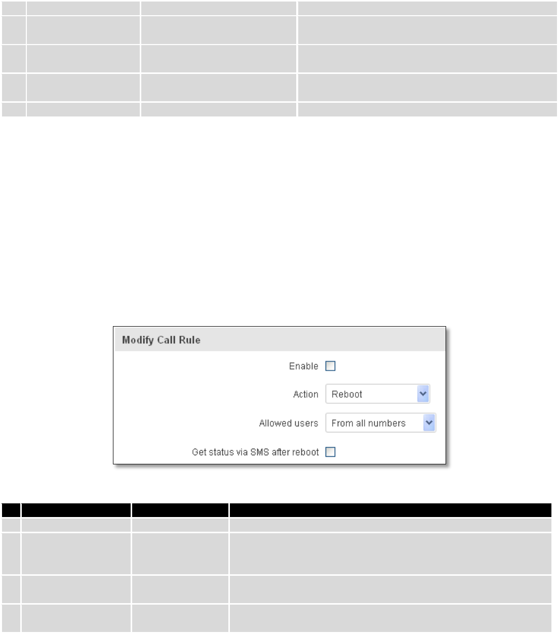
9.8.2 Call Utilities
Allow users to call to the router in order to perform one of the actions: Reboot, Get Status, turn Wi-Fi ON/OFF,
turn Mobile data ON/OFF. Only thing that is needed is to call routers SIM card number from allowed phone (user) and
RUT9 will perform all actions that are assigned for this particular number. To configure new action on call rules you just
need to click the Add button in the „New Call rule” section. After that, you get in to the “Modify Call Rule section”.
Field name
Sample
Explanation
1.
Enable
Enable/Disable
Enables the rule
2.
Action
Reboot
Action to be taken after receiving a call, you can choose from
following actions: Reboot, Send status, Switch Wi-Fi, Switch mobile
data.
3.
Allowed users
From all numbers
Allows to limit action triggering from all users, to user groups or
single user numbers
4.
Get status via SMS
after reboot
Enable/Disable
Enables automatic message sending with router status information
after reboot
119
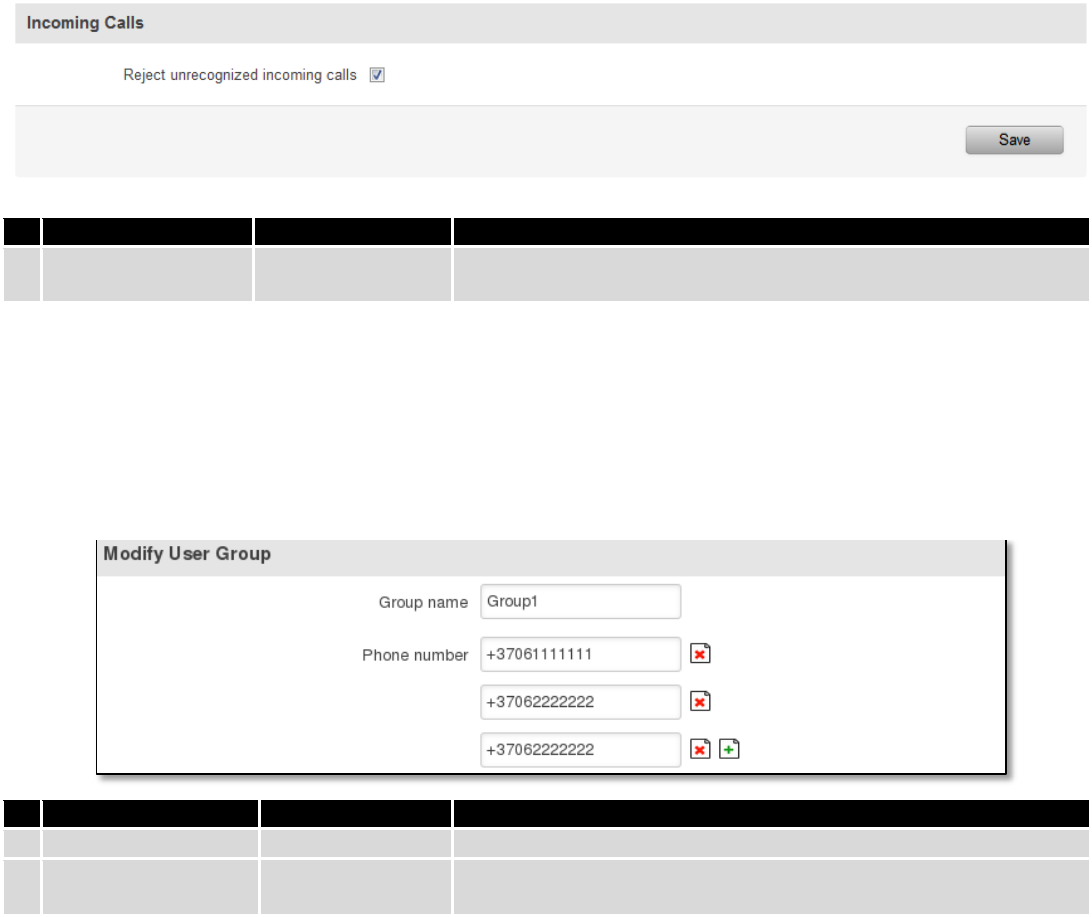
9.8.2.1 Incoming Calls
Field name
Sample
Explanation
1.
Reject unrecognized
incoming calls
Enable/Disable
If a call is made from number that is not in the active rule list, it can
be rejected with this option
9.8.3 User Groups
Give possibility to group phone numbers for SMS management purposes. You can then later use these groups in
all related SMS functionalities. This option helps if there are several Users who should have same roles when managing
router via SMS. You can create new user group by entering group name and clicking on Add button in “Create New User
Group” section. After that you get to “Modify User Group” section.
Field name
Sample
Explanation
1.
Group name
Group1
Name of grouped phone numbers
2.
Phone number
+37061111111
Number to add to users group, must match international format.
You can add phone numbers fields by clicking on the green + symbol
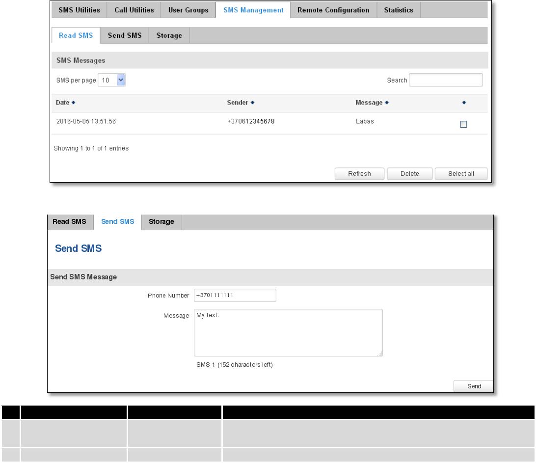
9.8.4 SMS Management
9.8.4.1 Read SMS
In SMS Management page Read SMS you can read and delete received/stored SMS.
120
9.8.4.2 Send SMS
Field name
Sample
Explanation
1.
Phone number
+3701111111
Recipients phone number. Should be preceded with country code,
i.e. “+370”
2.
Message
My text.
Message text, special characters are allowed.
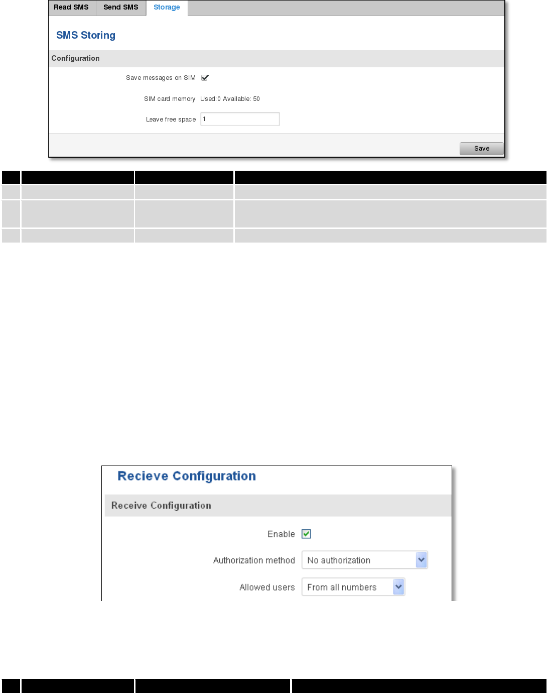
9.8.4.3 Storage
With storage option you can choose for router NOT to delete SMS from SIM card. If this option is not used, router
will automatically delete all incoming messages after they have been read. Message status “read/unread” is examined
every 60 seconds. All “read” messages are deleted.
121
Field name
Sample
Explanation
1.
Save messages on SIM
Enabled / Disabled
Enables received message storing on SIM card
2.
SIM card memory
Used: 0
Available: 50
Information about used/available SIM card memory
3.
Leave free space
1
How much memory (number of message should be left free
9.8.5 Remote Configuration
RUT9xx can be configured via SMS from another RUT9xx. You only have to select which configuration details have
to be sent, generate the SMS Text, type in the phone number and Serial number of the router that you wish to configure
and Send the SMS.
Total count of SMS is managed automatically. You should be aware of possible number of SMS and use this
feature at your own responsibility. It should not, generally, be used if you have high cost per SMS. This is especially
relevant if you will try to send whole OpenVPN configuration, which might acumulate ~40 SMS.
9.8.5.1 Receive configuration
This section controls how configuration initiation party should identify itself. In this scenario RUT955 itself is being
configured.
Field name
Values
Notes
122
1.
Enable
Enabled / Disabled
Enables router to receive configuration
1.
Authorization method
No authorization /
By serial
By administration password
Describes what kind of authorization to use for SMS
management. Method at Receiving and Sending ends
must match
2.
Allowed users
From all numbers
From group
From single number
Gives greater control and security measures
Note, that for safety reasons Authorization method should be configured before deployment of the router.
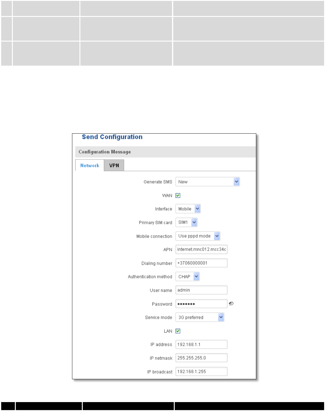
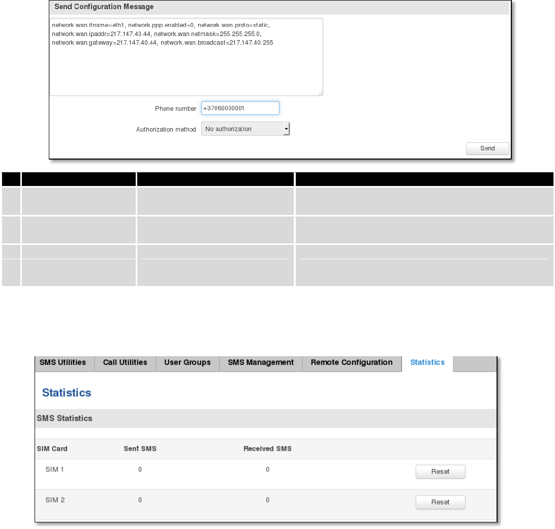
9.8.5.2 Send configuration
This section lets you configure remote RUT955 devices. The authorization settings must confirm to those that are
set on the receiving party.
Field name
Values
Notes

123
1.
Generate SMS
New/From current
configuration
Generate new SMS settings or use current device
configuration
2.
Interface
Mobile/Wired
Interface type used for WAN (Wide Area Network)
connection
3.
WAN
Enable/Disable
Include configuration for WAN (Wide Area Network)
4.
LAN
Enable/Disable
Include configuration for LAN (Local Area Network)
6.
Protocol
Static/DHCP
Network protocol used for network configuration
parameters management
7.
IP address
“217.147.40.44”
IP address that router will use to connect to the
internet
8.
IP netmask
“255.255.255.0”
That will be used to define how large the WAN (Wide
Area Network) network is
11.
IP gateway
“217.147.40.44”
The address where traffic destined for the internet is
routed to
12.
IP broadcast
“217.147.40.255”
A logical address at which all devices connected to a
multiple-access communications network are enabled
to receive datagrams.
13.
Primary SIM card
SIM1/SIM2
A SIM card that will be used as primary
14.
Mobile connection
Use pppd mode
Use ndis mode
An underlying agent that will be used for mobile data
connection creation and management
15.
APN
“internet.mnc012.mcc345.gprs”
(APN) is the name of a gateway between a GPRS or
3G mobile networks and another computer network,
frequently the public Internet.
16.
Dialing number
“+37060000001”
A phone number that will be used to establish a
mobile PPP (Point-to-Point Protocol) connection
17.
Authentication
method
CHAP/PAP/None
Select an authentication method that will be used to
authenticate new connections on your GSM carrier's
network
18.
User name
“admin”
User name used for authentication on your GSM
carrier's network
19.
Password
“password”
Password used for authentication on your GSM
carrier's network
20.
Service mode
Auto
4G (LTE ) preferred
4G (LTE) only
3G preferred
3G only
2G preferred
2G only
You can add as many phone numbers as you need.
Dropdown list with additional rows will show up if
you click on “add” icon at the end of phone number
row.
21.
IP address
“192.168.1.1”
IP address that router will use on LAN (Local Area
Network) network
22.
IP netmask
“255.255.255.0”
A subnet mask that will be used to define how large
the LAN (Local Area Network) network is
23.
IP broadcast
“192.168.1.255”
A logical address at which all devices connected to a
multiple-access communications network are enabled
to receive datagrams
124
Field name
Values
Notes
1.
Message text field
Generated configuration
message
Here you can review and modify configuration
message text to be sent
2.
Phone number
“+37060000001”
A phone number of router which will receive the
configuration
3.
Authorization method
No authorization
By serial
By router admin password
What kind of authorization to use for remote
configuration
9.8.6 Statistics
In statistics page you can review how much SMS was sent and received on both SIM card slots. You can also reset
the counters.
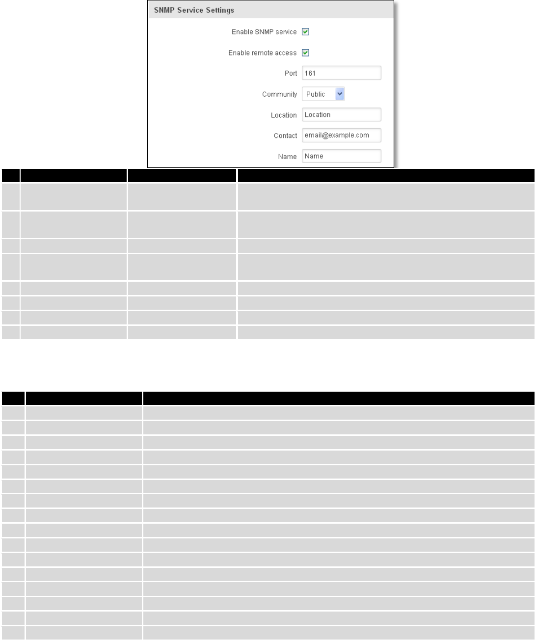
9.9 SNMP
SNMP settings window allows you to remotely monitor and send GSM event information to the server.
125
9.9.1 SNMP Settings
Field name
Sample
Explanation
1.
Enable SNMP service
Enable/Disable
Run SNMP (Simple Network Management Protocol) service on
system's start up
2.
Enable remote access
Enable/Disable
Open port in firewall so that SNMP (Simple Network
Management Protocol) service may be reached from WAN
3.
Port
161
SNMP (Simple Network Management Protocol) service's port
4.
Community
Public/Private/Custom
The SNMP (Simple Network Management Protocol) Community
is an ID that allows access to a router's SNMP data
5.
Community name
custom
Set custom name to access SNMP
6.
Location
Location
Trap named sysLocation
7.
Contact
email@example.com
Trap named sysContact
8.
Name
Name
Trap named sysName
Variables/OID
OID
Description
1.
1.3.6.1.4.1.99999.1.1.1
Modem IMEI
2.
1.3.6.1.4.1.99999.1.1.2
Modem model
3.
1.3.6.1.4.1.99999.1.1.3
Modem manufacturer
4.
1.3.6.1.4.1.99999.1.1.4
Modem revision
5.
1.3.6.1.4.1.99999.1.1.5
Modem serial number
6.
1.3.6.1.4.1.99999.1.1.6
SIM status
7.
1.3.6.1.4.1.99999.1.1.7
Pin status
8.
1.3.6.1.4.1.99999.1.1.8
IMSI
9.
1.3.6.1.4.1.99999.1.1.9
Mobile network registration status
10.
1.3.6.1.4.1.99999.1.1.10
Signal level
11.
1.3.6.1.4.1.99999.1.1.11
Operator currently in use
12.
1.3.6.1.4.1.99999.1.1.12
Operator number (MCC+MNC)
13.
1.3.6.1.4.1.99999.1.1.13
Data session connection state
14.
1.3.6.1.4.1.99999.1.1.14
Data session connection type
15.
1.3.6.1.4.1.99999.1.1.15
Signal strength trap
16.
1.3.6.1.4.1.99999.1.1.16
Connection type trap
126
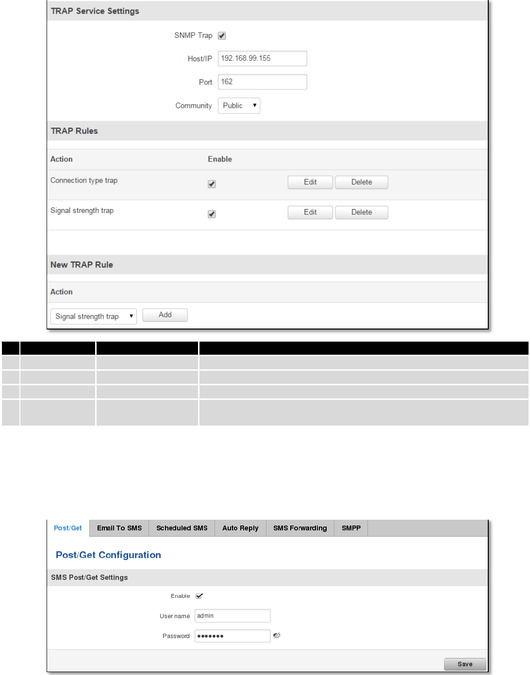
9.9.2 TRAP Settings
Field name
Sample
Explanation
1.
SNMP Trap
Enable/Disable
Enable SNMP (Simple Network Management Protocol) trap functionality
2.
Host/IP
192.168.99.155
Host to transfer SNMP (Simple Network Management Protocol) traffic to
3.
Port
162
Port for trap's host
4.
Community
Public/Private
The SNMP (Simple Network Management Protocol) Community is an ID
that allows access to a router's SNMP data
9.10 SMS Gateway
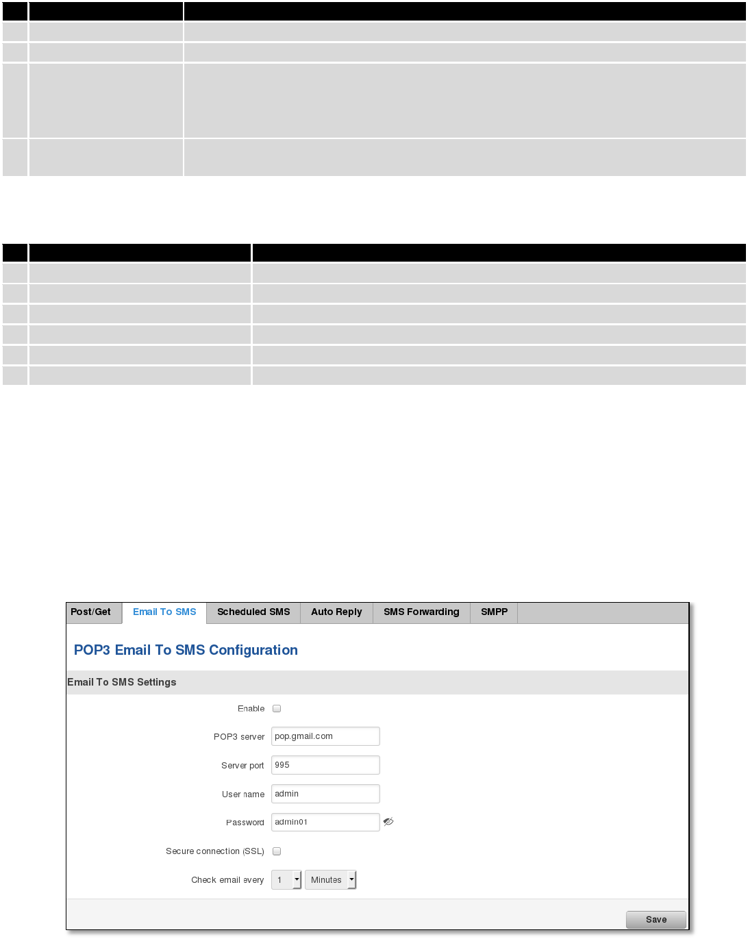
9.10.1 Post/Get Configuration
Post/Get Configuration allows you to perform actions by writing these requests URI after your device IP address.

127
Field name
Values
Notes
1.
Enable
Enabled / Disabled
Enable SMS management functionality through
POST/GET
2.
User name
admin
User name used for authorization
3.
Password
*******
Password used for authorization (default- admin01)
Do not forget to change parameters in the url according to your POST/GET Configuration!
9.10.1.1 SMS by HTTP POST/GET
It is possible to read and send SMS by using valid HTTP POST/GET syntax. Use web browser or any other
compatible software to submit HTTP POST/GET string to router. Router must be connected to GSM network when using
“SMS send” feature.
Action
POST/GET url e.g.
1.
View mobile
messages list
/cgi-bin/sms_list?username=admin&password=admin01
2.
Read mobile
message
/cgi-bin/sms_read?username=admin&password=admin01&number=1
3.
Send mobile
messages
/cgi-bin/sms_send?username=admin&password=admin01&number=0037060000001&text=testmessage
4.
View mobile
messages
total
/cgi-bin/sms_total?username=admin&password=admin01
5.
Delete mobile
message
/cgi-bin/sms_delete?username=admin&password=admin01&number=1
9.10.1.2 Syntax of HTTP POST/GET string
HTTP POST/GET string
Explanati
on
http://{IP_ADD
RESS}
/cgi-bin/sms_read?
username={your_user_name}&password={your_password}&number={MESSAGE_INDEX}
Read
message
/cgi-bin/sms_send?
username={your_user_name}&password={your_password}&number={PHONE_NUMBER}
&text={MESSAGE_TEXT}
Send
message
/cgi-bin/sms_delete?
username={your_user_name}&password={your_password}&number={MESSAGE_INDEX}
Delete
message
/cgi-bin/ sms_list? username={your_user_name}&password={your_password}
List all
message
s
/cgi-bin/sms_ total? username={your_user_name}&password={your_password}
Number
of
message
s in
memory
Note: parameters of HTTP POST/GET string are in capital letters inside curly brackets. Curly brackets (“{ }”) are not
needed when submitting HTTP POST/GET string.
128
9.10.1.3 Parameters of HTTP POST/GET string
Parameter
Explanation
1.
IP_ADDRESS
IP address of your router
2.
MESSAGE_INDEX
SMS index in memory
3.
PHONE_NUMBER
Phone number of the message receiver.
Note: Phone number must contain country code. Phone number format is:
00{COUNTRY_CODE} {RECEIVER_NUMBER}.
E.g.: 0037062312345 (370 is country code and 62312345 is receiver phone number)
4.
MESSAGE_TEXT
Text of SMS. Note: Maximum number of characters per SMS is 160. You cannot send
longer messages. It is suggested to use alphanumeric characters only.
After every executed command router will respond with return status.
9.10.1.4 Possible responses after command execution
Response
Explanation
1.
OK
Command executed successfully
2.
ERROR
An error occurred while executing command
3.
TIMEOUT
No response from the module received
4.
WRONG_NUMBER
SMS receiver number format is incorrect or SMS index number is incorrect
5.
NO MESSAGE
There is no message in memory by given index
6.
NO MESSAGES
There are no stored messages in memory
9.10.1.5 HTTP POST/GET string examples
http://192.168.1.1/cgi-bin/sms_read?username=admin&password=admin01&number=2
http://192.168.1.1/cgi-bin/sms_send?username=admin&password=admin01&number=0037060000001&text=message
http://192.168.1.1/cgi-bin/sms_delete?username=admin&password=admin01&number=4
http://192.168.1.1 /cgi-bin/sms_list?username=admin&password=admin01
http://192.168.1.1/cgi-bin/sms_total?username=admin&password=admin01
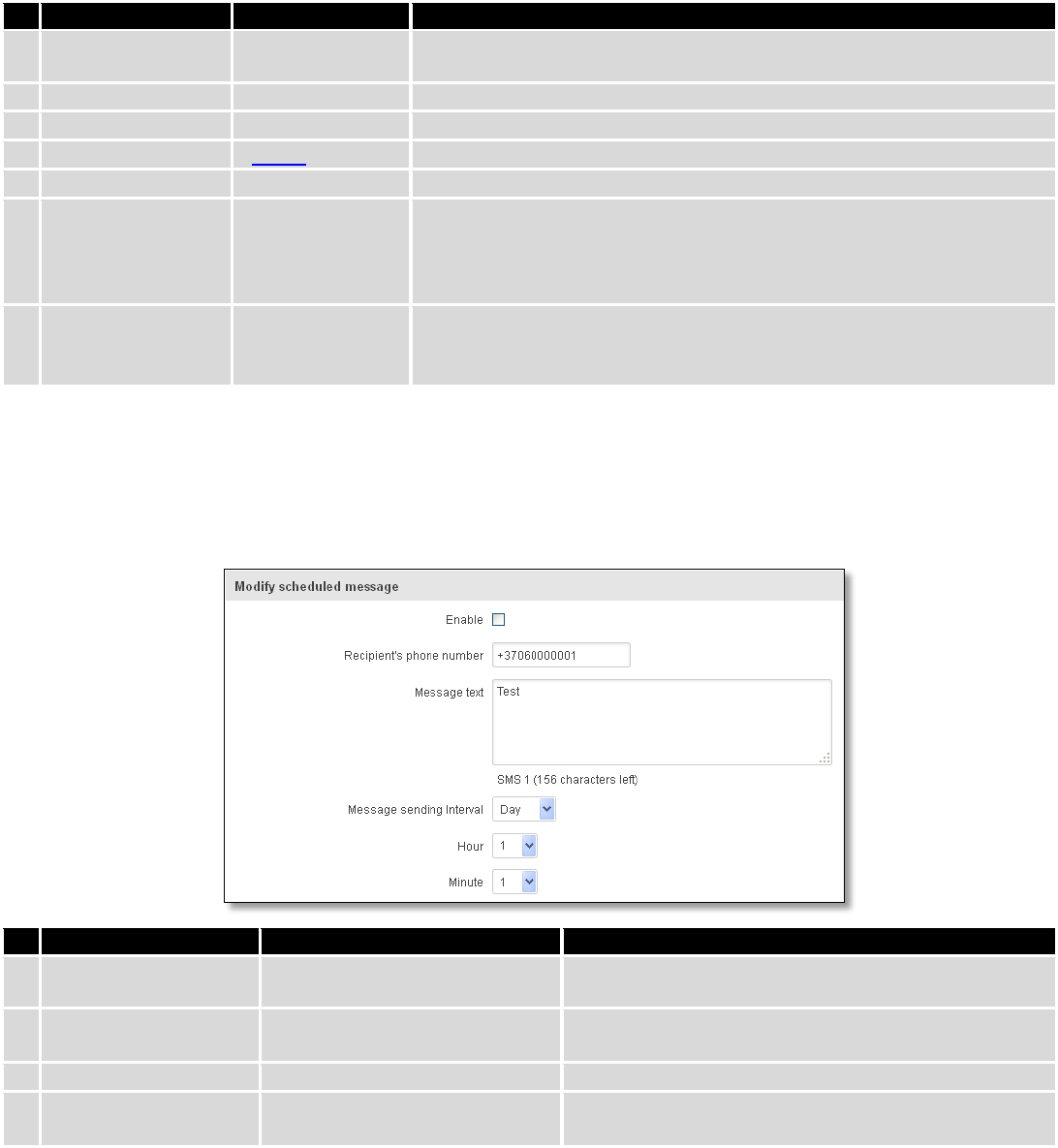
9.10.2 Email to SMS
129
Field name
Values
Notes
1.
Enable
Enable/Disable
Allows to convert received Email to SMS
2.
POP3 server
“pop.gmail.com”
POP3 server address
3.
Server port
“995”
Server authentication port
4.
User name
“admin”
User name using for server authentication
5.
Password
“admin01”
Password using for server authentication
6.
Secure connection
(SLL)
Enable/Disable
(SSL) is a protocol for transmitting private documents via the Internet.
SSL uses a cryptographic system that uses two keys to encrypt data − a
public key known to everyone and a private or secret key known only to
the recipient of the message.
7.
Check mail every
Minutes
Hours
Days
Mail checking period
9.10.3 Scheduled Messages
Scheduled messages allow to periodically sending mobile messages to specified number.
9.10.3.1 Scheduled Messages Configuration
Field name
Values
Notes
1.
Enable
Enable/Disable
Activates periodical messages sending.
2.
Recipient’s phone
number
“+37060000001”
Phone number that will receive messages.
3.
Message text
“Test”
Message that will be send.
4.
Message sending
interval
Day/Week/Month/Year
Message sending period.
9.10.4 Auto Reply Configuration
Auto reply allows replying to every message that router receives to everyone or to listed numbers only.
130
Field name
Values
Notes
1.
Enable
Enable/Disable
Enable auto reply to every received mobile message.
2.
Don’t save received
message
Enable/Disable
If enabled, received messages are not going to be
saved
3.
Mode
Everyone /
Listed numbers
Specifies from which senders received messages are
going to be replied.
4.
Message
“Text”
Message text that will be sent in reply.
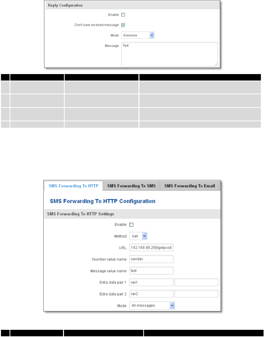
9.10.5 SMS Forwarding
9.10.5.1 SMS Forwarding To HTTP
This functionality forwards mobile messages from all or only specified senders to HTTP, using either POST or GET
methods.
Field name
Values
Notes
131
1.
Enable
Enable / Disable
Enable mobile message forwarding to HTTP
2.
Method
POST / GET
Defines the HTTP transfer method
3.
URL
192.168.99.250/getpost/index.php
URL address to forward messages to
4.
Number value name
“sender”
Name to assign for sender’s phone number value in
query string
5.
Message value name
“text”
Name to assign for message text value in query string
6.
Extra data pair 1
Var1 - 17
If you want to transfer some extra information
through HTTP query, enter variable name on the left
field and its value on the right
7.
Extra data pair 2
Var2 – “go”
If you want to transfer some extra information
through HTTP query, enter variable name on the left
field and its value on the right
8.
Mode
All messages/From listed numbers
Specifies which senders messages to forward
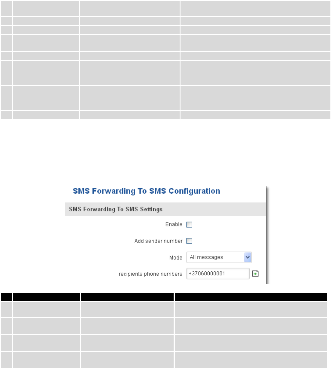
9.10.5.2 SMS Forwarding to SMS
This functionality allows forwarding mobile messages from specified senders to one or several recipients.
Field name
Values
Notes
1.
Enable
Enable / Disable
Enable mobile message forwarding
2.
Add sender number
Enable / Disable
If enabled, original senders number will be added at
the end of the forwarded message
3.
Mode
All message /
From listed numbers
Specifies from which senders received messages are
going to be forwarded.
4.
Recipients phone
numbers
+37060000001
Phone numbers to which message is going to be
forwarded to
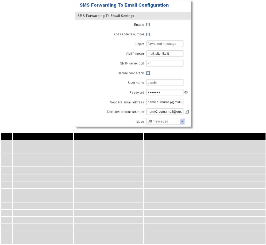
9.10.5.3 SMS Forwarding to Email
This functionality forwards mobile messages from one or several specified senders to email address.
132
Field name
Values
Notes
1.
Enable
Enable / Disable
Enable mobile message forwarding to email
2.
Add sender number
Enable / Disable
If enabled, original senders number will be added at
the end of the forwarded message
3.
Subject
“forwarded message”
Text that will be inserted in email Subject field
4.
SMTP server
mail.teltonika.lt
Your SMTP server’s address
5.
SMTP server port
25
Your SMTP server’s port number
6.
Secure connection
Enable / Disable
Enables the use of cryptographic protocols, enable
only if your SMTP server supports SSL or TLS
7.
User name
“admin”
Your full email account user name
8.
Password
*******
Your email account password
9.
Sender’s email address
name.surname@gmail.com
Your address that will be used to send emails from
10.
Recipient’s email address
name2.surname2@gmail.com
Address that you want to forward your messages to
11.
Mode
All messages / from listed
numbers
Choose which senders messages to forward to email
133
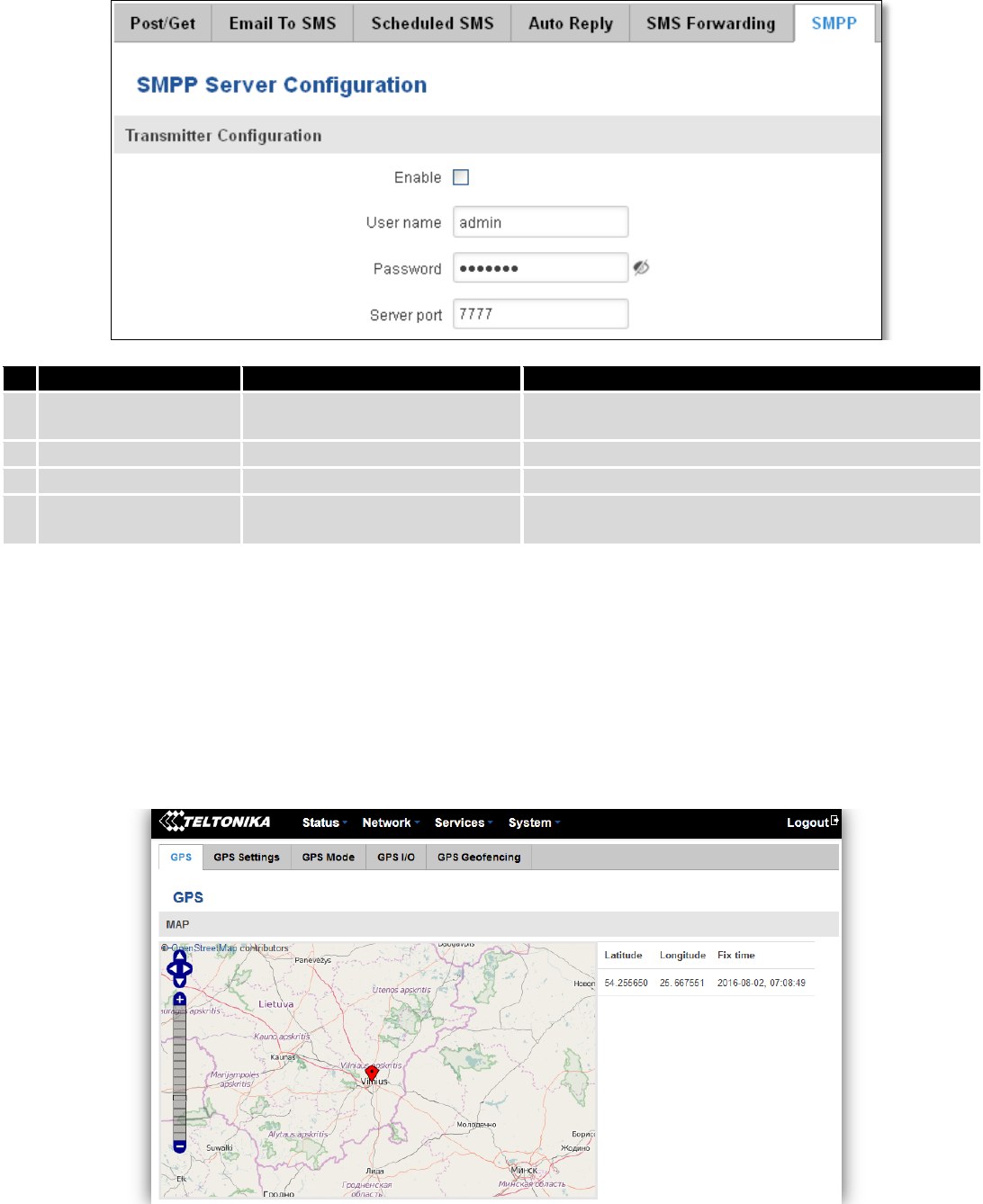
9.10.6 SMPP
Field name
Values
Explanation
1.
Enable
Enable/Disable
Enables SMPP server
2.
User name
admin
User name for authentication on SMPP server
3.
Password
●●●●●●●
Password for authentication on SMPP server
4.
Server port
7777
A port will be used for SMPP server communications.
Allowed all not used ports [0-65535]
9.11 GPS
9.11.1 GPS
On this page you can view your current coordinates and position on map
134
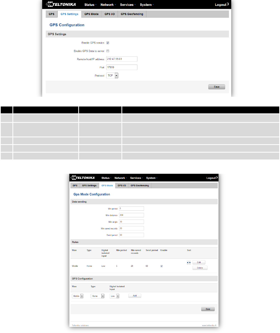
9.11.2 GPS Settings
This is the GPS parameters comfiguration page.
9.11.3 GPS Mode
Data sending
Field name
Values
Notes
1.
Enable GPS service
Enable / Disable
By enabling it will start generate your location coordinates
2.
Enable GPS Data to server
Enable / Disable
By enabling it will start generate your location coordinates and
transfer them to specified server
3.
Remote host / IP address
212.47.99.61
Server IP address or domain name to send coordinates to
4.
Port
17050
Server port used for data transfer
5.
Protocol
TCP or UDP
Protocol to be used for coordinates data transfer to server
135
Rules
This table shows created GPS rules for data sending.
GPS Configuration
GPS configuration section allows to save several different configurations for GPS data collection, active
configuration is automaticaly selected when configured conditions are met.
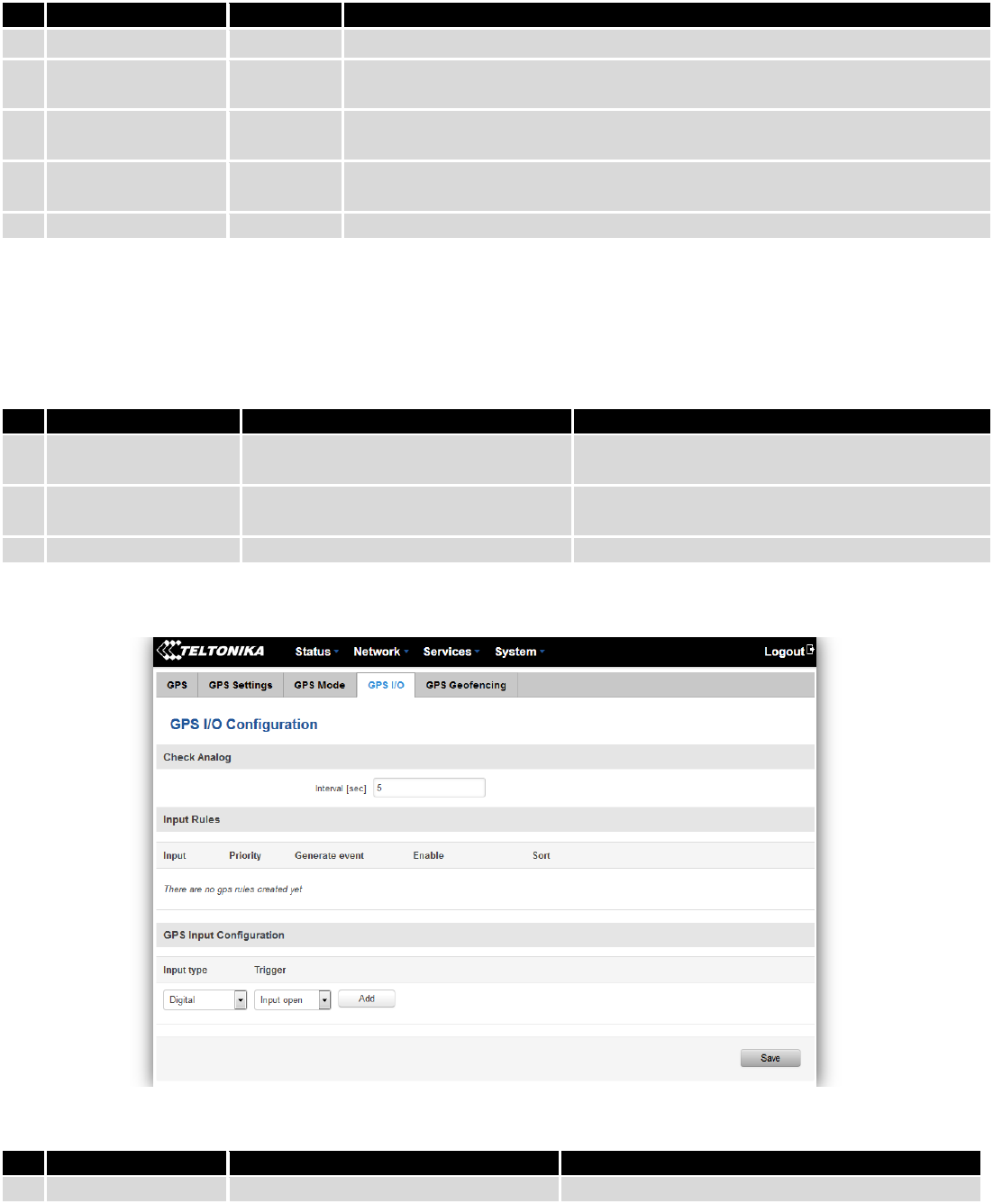
9.11.4 GPS I/O
Check Analog
Input Rules
In this table shows created Input rules.
Field name
Values
Notes
1.
Min period
5
Period (in seconds) for data collection
2.
Min distance
200
Distance difference (in meters) between last registered and current
coordinates to collect data (even if Min period have not passed yet)
3.
Min angle
30
Minimal angle difference between last registered and current coordinates to
collect data (even if Min period have not passed yet)
4.
Min saved records
20
Minimal amount of coordinates registered, to send them to server
immediately (even if Send period have not passed yet)
5.
Send period
50
Period for sending collected data to server
Field name
Values
Notes
1.
WAN
Mobile/ Wired/ WiFi
Interface which needs to be used to activate this
configuration
2.
Type
Home/ Roaming/ Both
Mobile connection state needed to activate this
configuration
3.
Digital Isolated Input
Low logic level/ High logic level/ Both
Input state needed to activate this configuration
Field name
Values
Notes
1.
Interval (sec)
5
Interval to check analog input value
136
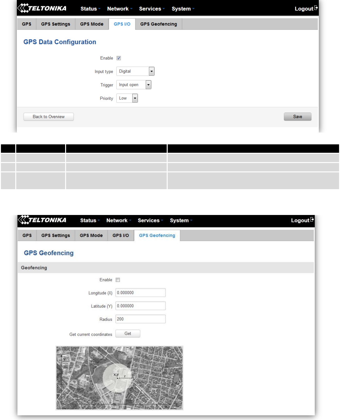
GPS Input Configuration
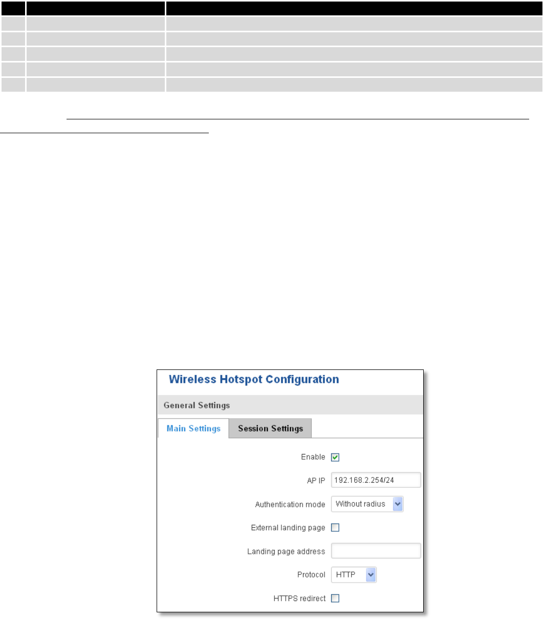
9.11.5 GPS Geofencing
Field name
Values
Notes
1.
Input Type
Digital/ Digital isolated/ Analog
Select type on your own intended configuration
2.
Trigger
Input open/ Input shorted/ Both
Select trigger event for your own intended configuration
3.
Priority
Low/ High/ Panic
Different priority settings ads different priority flags to
event packet, and they can be displayed differently
137
Geofencing is a feature which can detect whenever a device enters or leaves customized area.
To receive SMS or email when entering or leaving geofence zone, go to Status -> Events Log -> Events
reporting page and configure GPS event type!
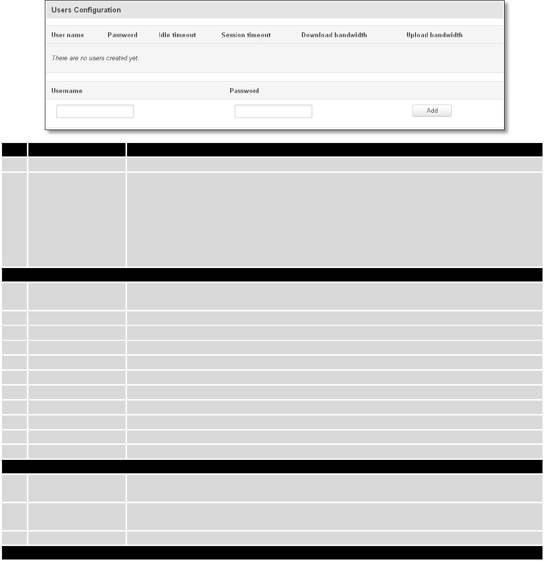
9.12 Hotspot
Wireless hotspot provides essential functionality for managing an open access wireless network. In addition to
standard RADIUS server authentication there is also the ability to gather and upload detailed logs on what each device
(denoted as a MAC address) was doing on the network (what sites were traversed, etc.).
9.12.1 General settings
9.12.1.1 Main settings
Field name
Notes
1.
Enable
Enable/Disable GPS Geofencing functionality
2.
Longitude (X)
Longitude of selected point
3.
Latitude (Y)
Latitude of selected point
4.
Radius
Radius of selected area
5
Get current coordinates
Get current device coordinates from GPS
138
Field name
Explanation
1.
Enabled
Check this flag to enable hotspot functionality on the router.
2.
AP IP
Access Point IP address. This will be the address of the router on the hotspot network. The
router will automatically create a network according to its own IP and the CIDR number
that you specify after the slash. E.g. “192.168.2.254/24” means that the router will create
a network with the IP address 192.168.182.0, netmask 255.255.255.0 for the express
purpose of containing all the wireless clients. Such a network will be able to have 253
clients (their IP addresses will be automatically granted to them and will range from
192.168.2.1 to 192.168.2.253).
Authentication mode: External radius
1.
Radius server #1
The IP address of the RADIUS server that is to be used for Authenticating your wireless
clients.
2.
Radius server #2
The IP address of the second RADIUS server.
3.
Authentication port
RADIUS server authentication port.
4.
Accounting port
RADIUS server accounting port.
5.
Radius secret key
The secret key is used for authentication with the RADIUS server
6.
UAM port
Port to bind for authenticating clients
7.
UAM UI port
UAM UI port
8.
UAM secret
Shared secret between UAM server an hotspot
9.
NAS Identifier
NAS Identifier
10.
Swap octets
Swap the meaning of input octets and output as it related to RADIUS attributes
11.
Location name
The name of location
Authentication mode: Internal radius/Without radius
1.
External landing
page
Enables the use of external landing page.
2.
Landing page
address
The address of external landing page
3.
HTTPS redirect
Redirects HTTP pages to landing page.
Authentication mode: SMS OTP
139
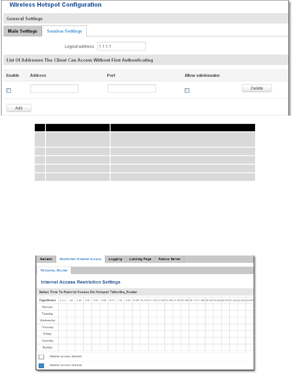
9.12.1.2 Session settings
Field name
Explanation
1.
Logout address
IP address to instantly logout a client addressing it
2.
Enable
Enable address accessing without first authenticating
3.
Address
Domain name, IP address or network segment
4.
Port
Port number
5.
Allow subdomains
Enable/Disable subdomains
9.12.2 Internet Access Restriction Settings
Allows disable internet access on specified day and hour of every week.
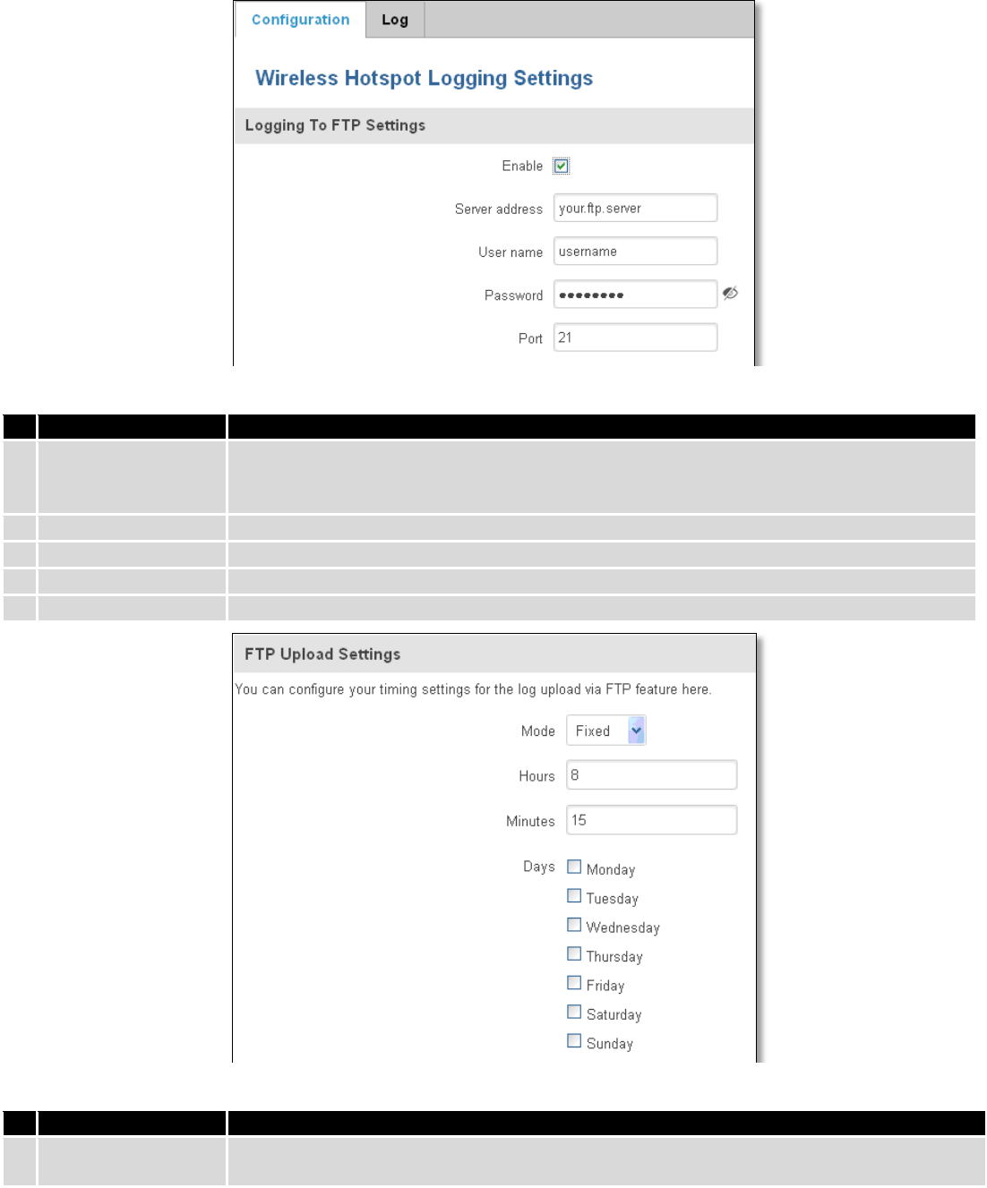
140
9.12.3 Logging
9.12.3.1 Configuration
Field name
Explanation
1.
Enable
Check this box if you want to enable wireless traffic logging. This feature will produce logs
which contain data on what websites each client was visiting during the time he was
connected to your hotspot.
2.
Server address
The IP address of the FTP server to which you want the logs uploaded.
3.
Username
The username of the user on the aforementioned FTP server.
4.
Password
The password of the user.
5.
Port
The TCP/IP Port of the FTP server.
Field name
Explanation
1.
Mode
The mode of the schedule. Use “Fixed” if you want the uploading to be done on a specific
time of the day. Use “Interval” if you want the uploading to be done at fixed interval.
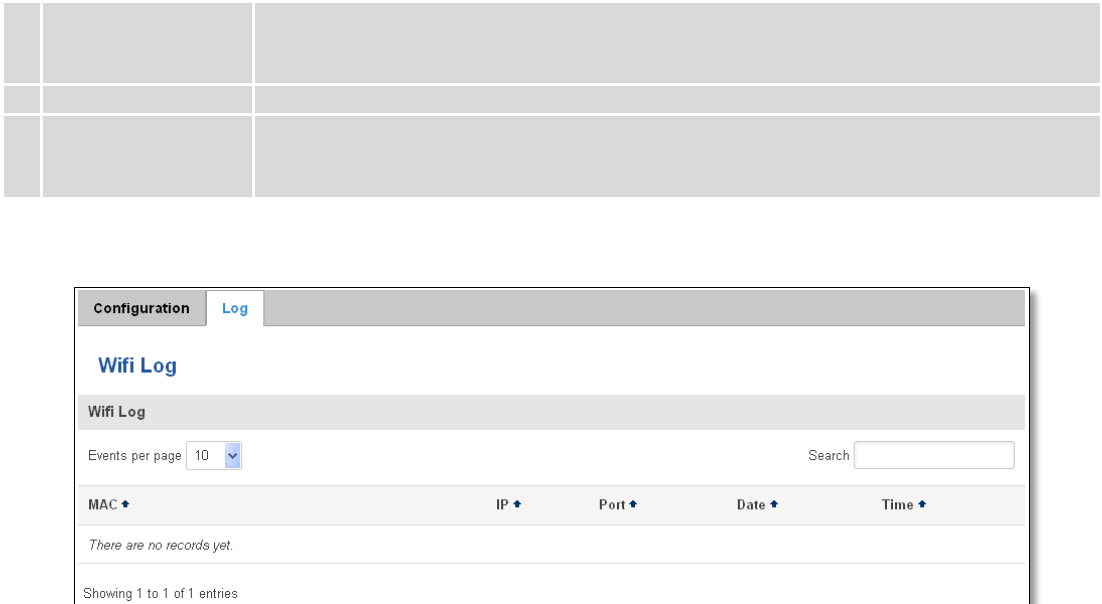
141
2.
Interval
Shows up only when “Mode” is set to Interval. Specifies the interval of regular uploads on
one specific day. E.g. If you choose 4 hours, the uploading will be done on midnight, 4:00,
8:00, 12:00, 16:00 and 20:00.
3.
Days
Uploading will be performed on these days only
4.
Hours, Minutes
Shows up only when “Mode” is set to Fixed. Uploading will be done on that specific time of
the day. E.g. If you want to upload your logs on 6:48 you will have to simply enter hours: 6
and minutes: 48.
9.12.3.2 Log
9.12.4 Landing Page
9.12.4.1 General Landing Page Settings
With this functionality you can customize your Hotspot Landing page.
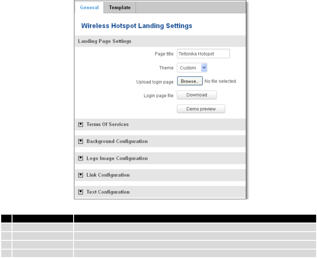
142
Field name
Explanation
1.
Page title
Will be seen as landing page title
2.
Theme
Landing page theme selection
3.
Upload login page
Allows to upload custom landing page theme
4.
Login page file
Allows to download and save your landing page file
In the sections – “Terms Of Services”, “Background Configuration”, “Logo Image Configuration”, “Link
Configuration”, “Text Configuration” you can customize various parameters of landing page components.
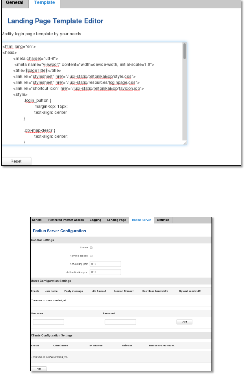
143
9.12.4.2 Template
In this page you can review landing page template HTML code and modify it.
9.12.5 Radius server configuration
An authentication and accounting system used by many Internet Service Providers (ISPs). When you dial in to the
ISP you must enter your username and password. This information is passed to a RADIUS server, which checks that the
information is correct, and then authorizes access to the ISP system.
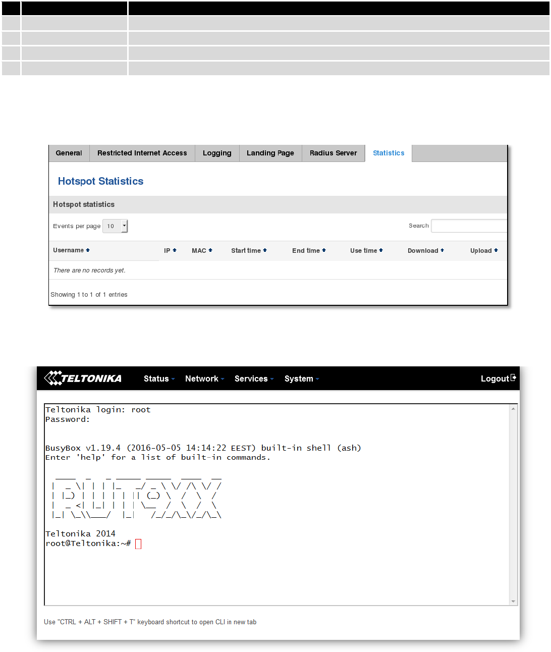
144
Field name
Explanation
1.
Enable
Activates an authentication and accounting system
2.
Remote access
Activates remote access to radius server
3.
Accounting port
Port on which to listen for accounting
4.
Authentication port
Port on which to listen for authentication
9.12.6 Statistics
On hotspot statistics page you can review statistical information about hotspot instances.
9.13 CLI
CLI or Comand Line Interface functionality allows you to enter and execute comands into routers terminal.
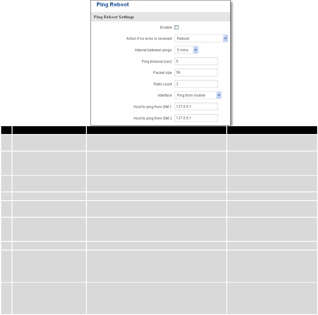
145
9.14 Auto Reboot
9.14.1 Ping Reboot
Ping Reboot function will periodically send Ping command to server and waits for echo receive. If no echo is
received router will try again sending Ping command defined number times, after defined time interval. If no echo is
received after the defined number of unsuccessful retries, router will reboot. It is possible to turn of the router
rebooting after defined unsuccessful retries. Therefore this feature can be used as “Keep Alive” function, when router
Pings the host unlimited number of times. Possible actions if no echo is received: Reboot, Modem restart, Restart
mobile connection, (Re) register, None.
Field name
Explanation
Notes
1.
Enable
This check box will enable or disable Ping reboot
feature.
Ping Reboot is disabled by
default.
2.
Action if no echo is
received
Action after the defined number of unsuccessful
retries
No echo reply for sent ICMP
(Internet Control Message
Protocol) packet received
3.
Interval between pings
Time interval in minutes between two Pings.
Minimum time interval is 5
minutes.
4.
Ping timeout (sec)
Time after which consider that Ping has failed.
Range(1-9999)
5.
Packet size
This box allows to modify sent packet size
Should be left default, unless
necessary otherwise
6.
Retry count
Number of times to try sending Ping to server after
time interval if echo receive was unsuccessful.
Minimum retry number is 1.
Second retry will be done after
defined time interval.
8.
Interface
Interface used for connection
7.
Host to ping from SIM 1
IP address or domain name which will be used to
send ping packets to. E.g. 127.0.0.1 (or
www.host.com if DNS server is configured
correctly)
Ping packets will be sending
from SIM1.
8.
Host to ping from SIM 2
IP address or domain name which will be used to
send ping packets to. E.g. 127.0.0.1 (or
www.host.com if DNS server is configured
correctly)
Ping packets will be sending
from SIM2.
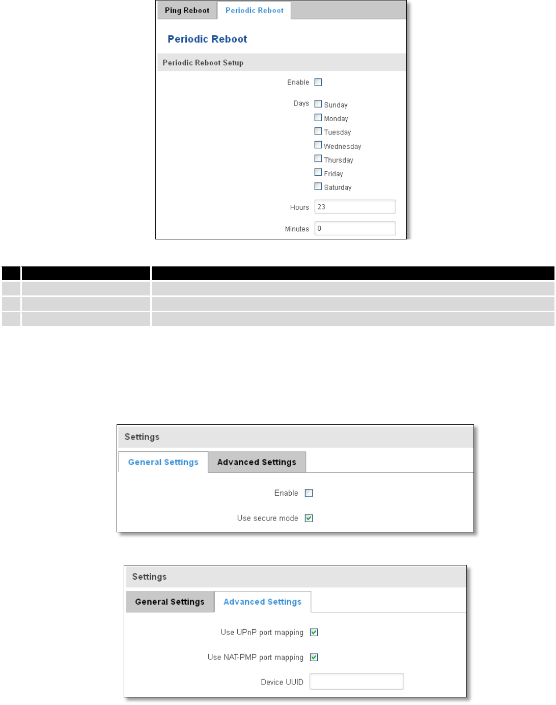
146
9.14.2 Periodic Reboot
Field name
Explanation
1.
Enable
This check box will enable or disable Periodic reboot feature.
2.
Days
This check box will enable router rebooting at the defined days.
3.
Hours, Minutes
Uploading will be done on that specific time of the day
9.15 UPNP
9.15.1 General Settings
UPnP allows clients in the local network to automatically configure the router.
9.15.2 Advanced Settings
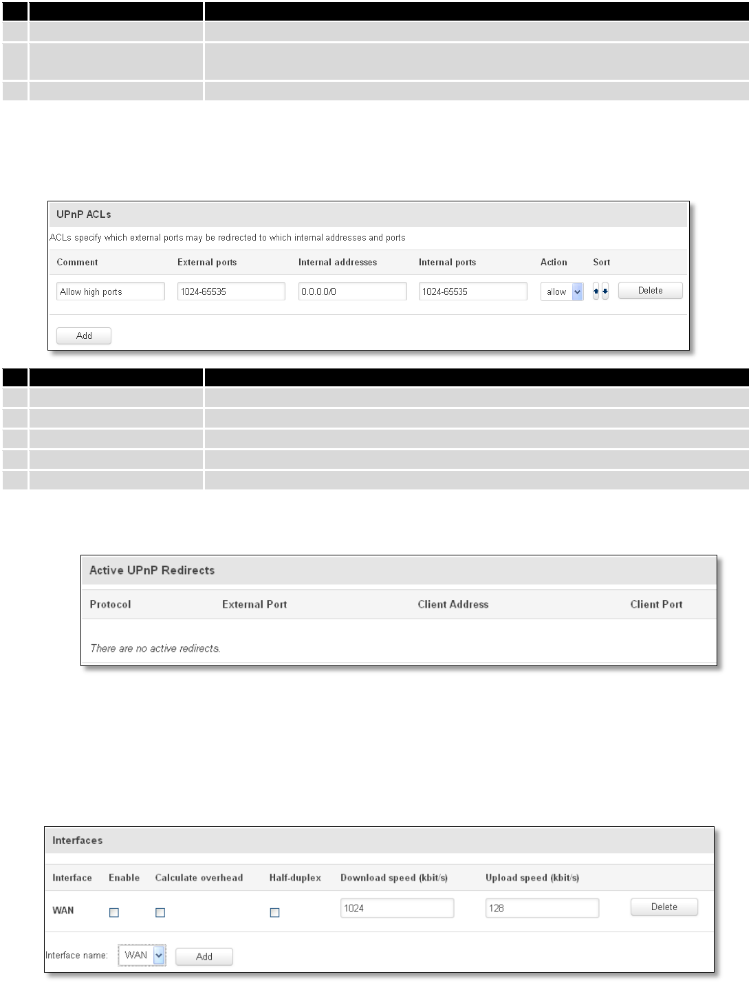
147
Field name
Explanation
1.
Use UPnP port mapping
Enable UPnP port mapping functionality
2.
Use NAT-PMP port
mapping
Enable NAT-PMP mapping functionality
3.
Device UUID
Specify Universal unique ID of the device
9.15.3 UPnP ACLs
ACLs specify which external ports may be redirected to which internal addresses and ports.
Field name
Explanation
1.
Comment
Add comment to this rule
2.
External ports
External ports which may be redirected
3.
Internal addresses
Internal address to be redirect to
4.
Internal ports
Internal ports to be redirect to
5.
Action
Allow or forbid UPNP service to open the specified port
9.15.4 Active UPnP Redirects
9.16 QoS
QoS (Quality of Service) is the idea that transmission rates, error rates, and other characteristics can be measured,
improved, and, to some extent, guaranteed in advance. QoS is of particular concern for the continuous transmission of
high-bandwidth video and multimedia information.
QoS can be improved with traffic shaping techniques such as packet, network traffic, and port prioritization.
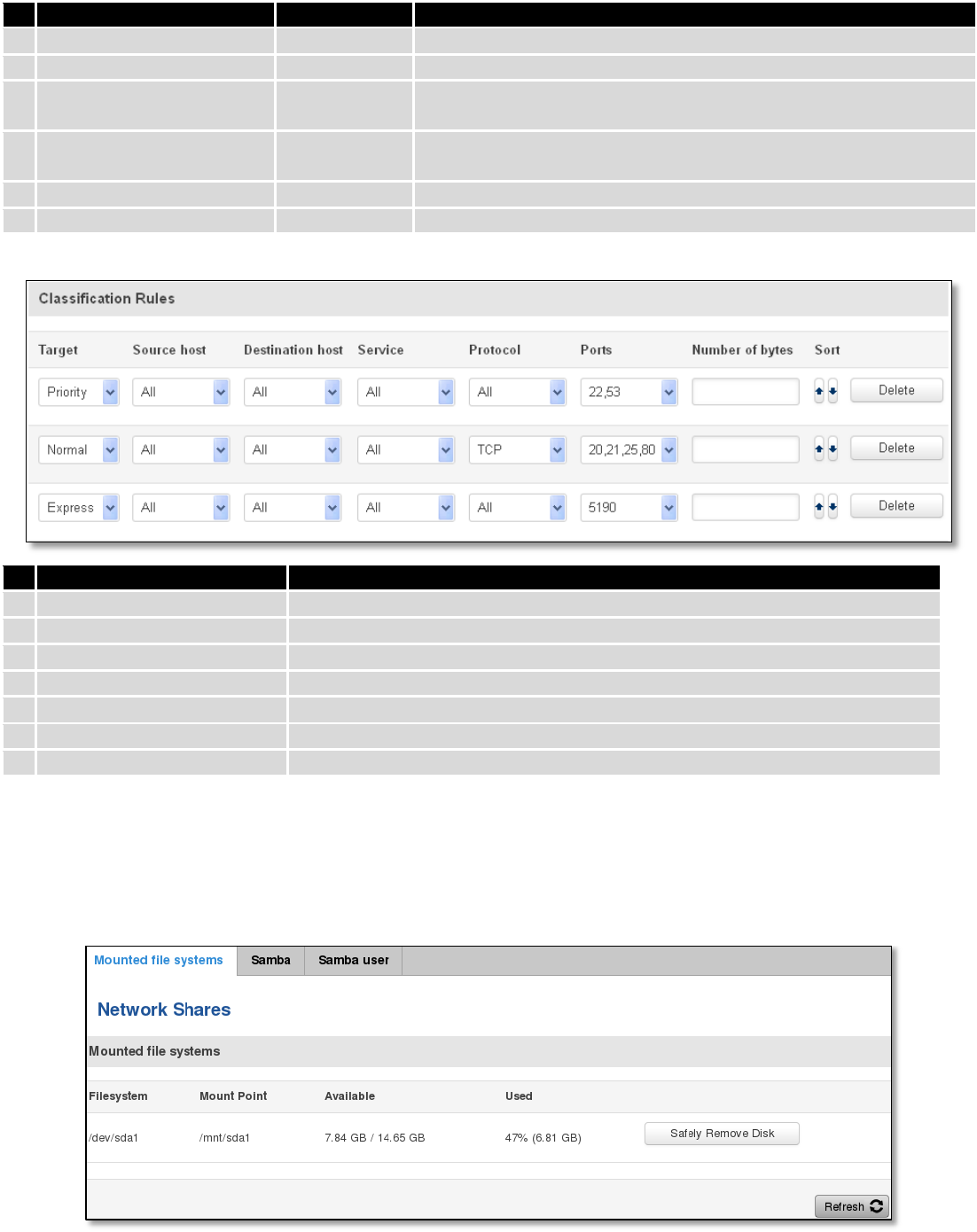
148
Field name
Value
Explanation
1.
Interface
WAN/LAN/PPP
2.
Enable
Enable/Disable
Enable/disable settings
3.
Calculate overhead
Enable/Disable
Check to decrease upload and download ratio to prevent link
saturation
4.
Half-duplex
Enable/Disable
Check to enable data transmission in both direction on a single
carrier
5.
Download speed (kbit/s)
1024
Specify maximal download speed
6.
Upload speed (kbit/s)
128
Specify maximal upload speed
Field name
Explanation
1.
Target
Select target for which rule will be applied
2.
Source host
Select host from which data will be transmitted
3.
Destination host
Select host to which data will be transmitted
4.
Service
Select service for which rule will be applied
5.
Protocol
Select data transmission protocol
6.
Ports
Select which port will be used for transmission
7.
Number of bytes
Specify the maximal number of bytes for connection
9.17 Network Shares
9.17.1 Mounted File Systems
On this page you can review mounted file systems (for example USB flashdrive).
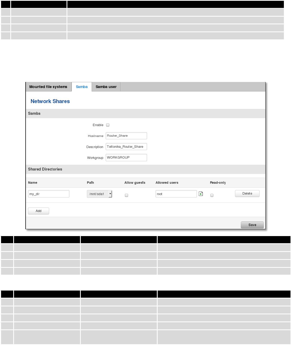
149
Field name
Explanation
1.
File System
Filesystem on which additional file system is mounted
2.
Mount Point
Directory available for mounting additional file system
3.
Available
Total memory available in mounted system
4.
Used
Free memory in mounted system
9.17.2 Samba
Samba functionality allows network sharing for specified directories.
Field name
Values
Notes
1.
Enable
Enable / Disable
Enables Samba service
2.
Hostname
Router_Share
Name of samba server
3.
Description
Teltonika_Router_Share
Short server description
4.
Workgroup
WORKGROUP
Name of the workgroup
In Shared Directories section you can add directories to be shared and configure some usage parameters:
Field name
Values
Notes
1.
Name
My_dir
Name of the shared directory
2.
Path
/mnt/sda1
Path to directory to be shared
3.
Allow guests
Enable / Disable
Enable viewing the directory as a guest
4.
Allowed users
root
Specify users to be allowed to share this directory
5.
Read-only
Enable / Disable
Sets user’s wrights in the specified directory to read-
only
9.17.3 Samba User
In this page you can add new samba users.
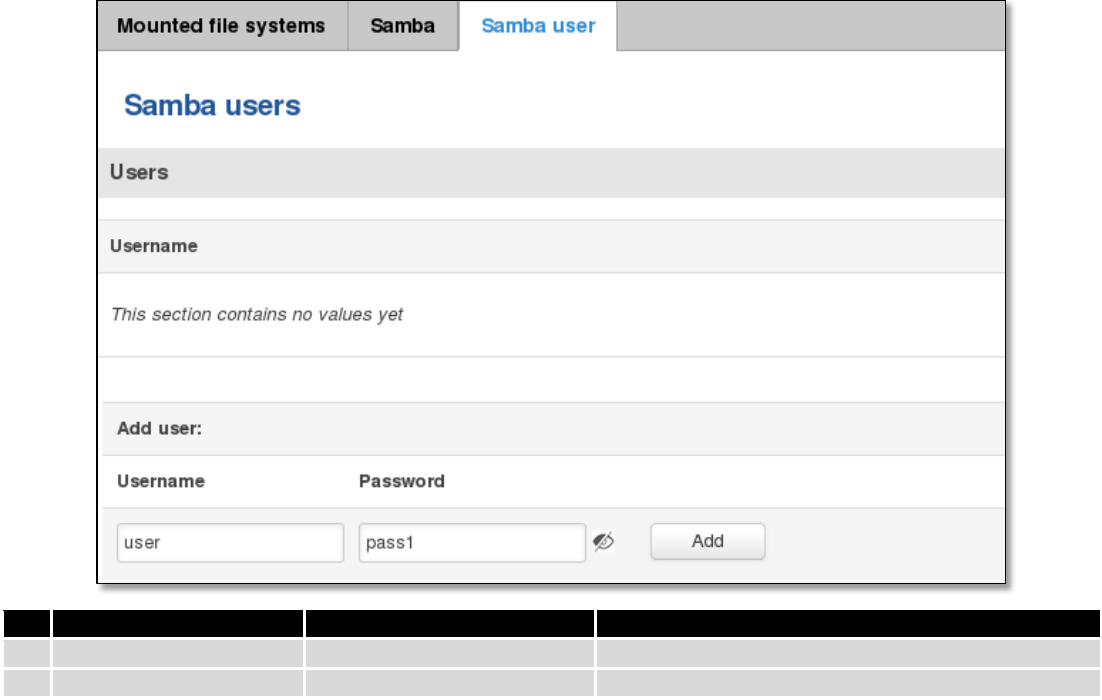
150
Field name
Values
Notes
1.
Username
user
Name of new user
2.
Password
Pass1
New user’s password
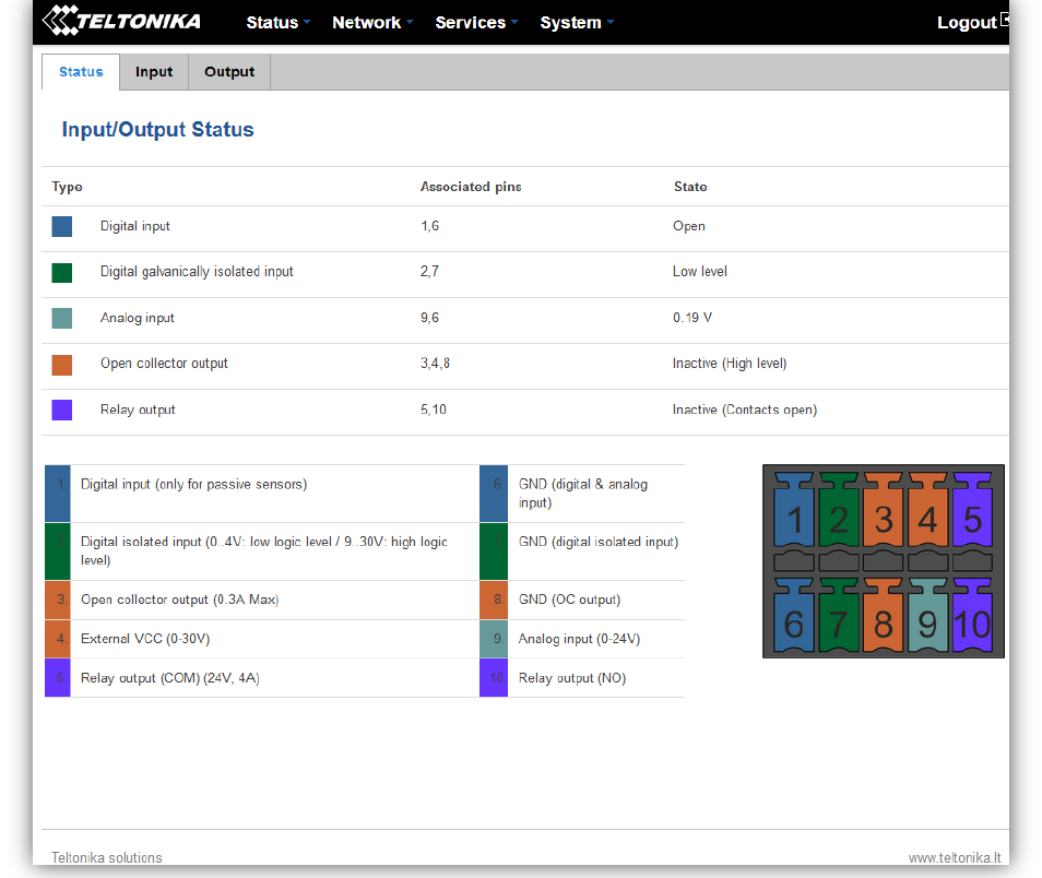
151
9.18 Input/Output
9.18.1 Status
In this page you can review the current state of all router’s inputs and outputs.
9.18.2 Input
Allows you to set up input parameters and specify what actions should be taken after triggering event of any
input. In check analog section you can change the analog input checking interval.
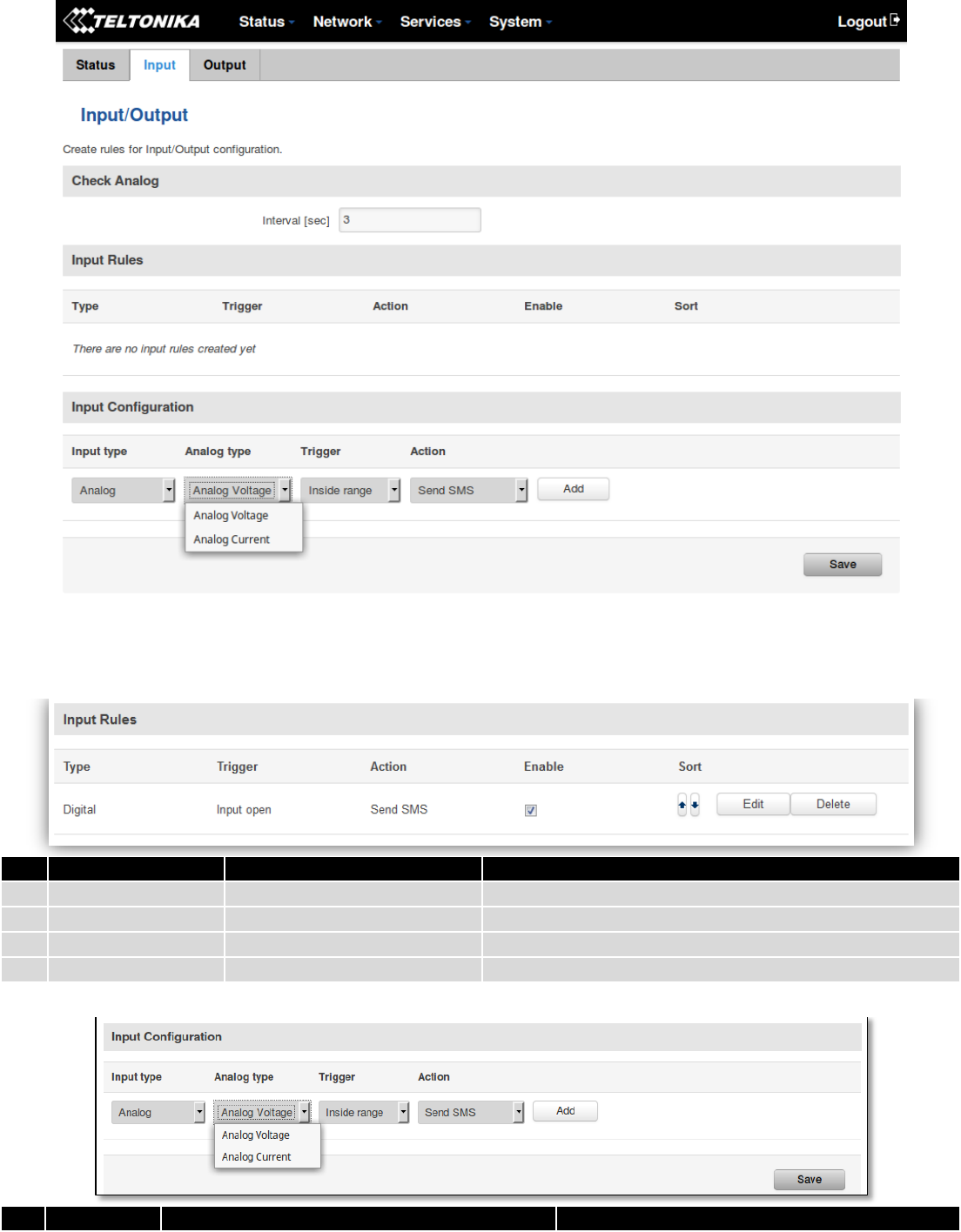
152
In the input rules section you can create and modify the rules for action after specific input triggering.
Field name
Sample
Explanation
1.
Type
Digital/Digital isolated/Analog
Specifies input type
2.
Triger
Input open
Specifies for which trigger rule is applied
3.
Action
Send SMS
Specifies what action is done
4.
Enable
Enable/Disable
Enable input configuration
Field name
Values
Explanation
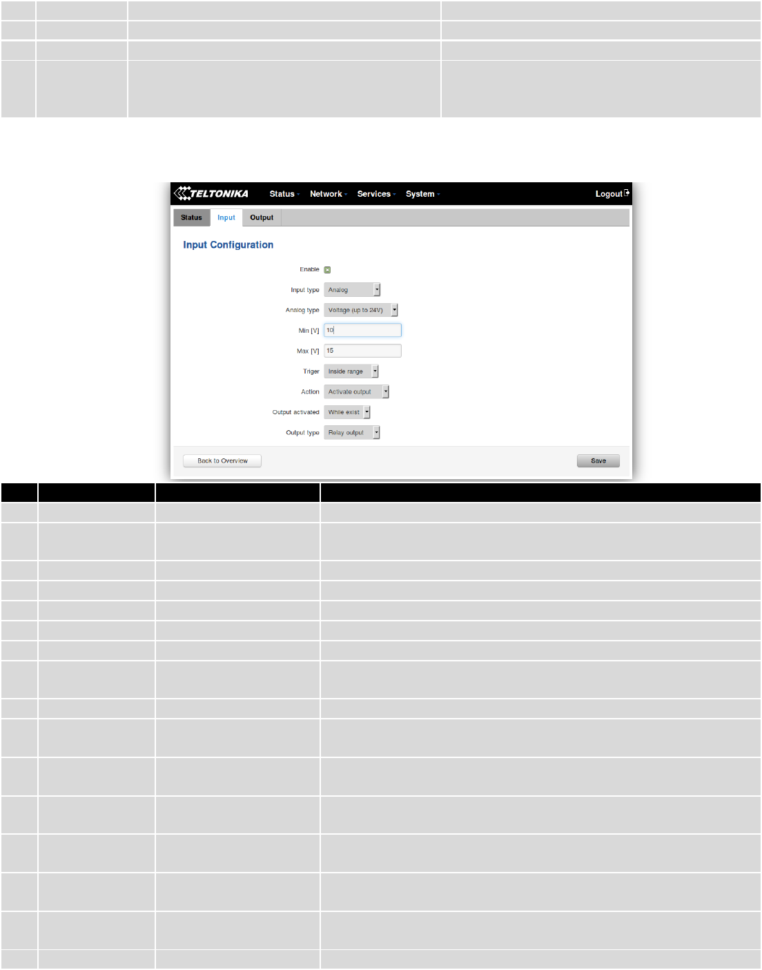
153
1.
Input type
Digital/Digital isolated/Analog
Specify input type
1.a
Analog type
Analog Voltage/Analog Current
Specify voltage or current measurement
2.
Triger
Input open / Input shorted/ both
Specify for which trigger rule will be applied
3.
Action
Send SMS/ Change SIM card/ Send email/
Change profile/ Turn WiFi ON or OFF/Reboot/
Output
Choose what action will be done after input
triggering
After clicking on ADD button (Or Edit, if the rule is already created) you get the second input configuration page
with extra parameters to set.
Field name
Sample
Explanation
1.
Enable
Enable/Disable
Enable this input rule
2.
Input type
Digital/Digital
isolated/Analog
Specify the input type
3.
Min V/mA
10
Specify minimum voltage/current. Only shown when Input type is Analog
4.
Max V/mA
20
Specify maximum voltage/current. Only shown when Input type is Analog
5.
Triger
Input open
Specify for which trigger rule will be applied
6.
Action
Send SMS
Specify what action to do
7.
SMS text
Input
Specify message to send in SMS
8.
Recipients
phone number
+37012345678
Phone number where you will get SMS. Only shown when Action is
Send SMS
9.
Subject
Input
Specify subject of email. Only shown when Action is Send email
10.
Message
Input
Specify message to send in email. Only shown when Action is Send
email
11.
SMTP server
mail.example.com
Specify SMTP (Simple Mail Transfer Protocol) server. Only shown
when Action is Send email
12.
SMTP server
port
123
Specify SNMP server port. Only shown when Action is Send email
13.
Secure
connection
Enable/Disable
Specify if server support SSL or TLS. Only shown when Action is Send
email
14.
User name
username
Specify user name to connect SNMP server. Only shown when Action
is Send email
15.
Password
password
Specify the password of the user. Only shown when Action is Send
email
16.
Sender's email
sender@example.com
Specify your email address. Only shown when Action is Send email
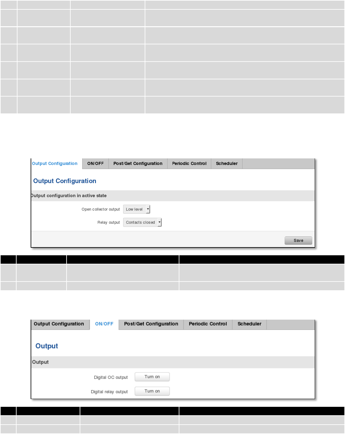
154
address
17.
Recipient's
email address
recipient@example.com
Specify for whom you want to send email. Only shown when Action
is Send email
18.
Sim
Primary/ Secondary
Specify which one SIM card will be changed. Only shown when
Action is Change SIM Card
19.
Profile
Admin
Specify which profile will be set and used. Only shown when Action is
Change Profile
20.
Reboot after (s)
4
Device will reload after a specified time (in seconds). Only shown
when Action is Reboot
21.
Output
activated
10
Output will be activated for specified time (in seconds) , or while
exists.
22.
Output type
Digital OC output/ Relay
output
Specify output type, which will be activated, depending on output
time. Only shown when Action is Activate output
9.18.3 Output
9.18.3.1 Output Configuration
Field name
Sample
Explanation
1.
Open collector
output
Low level / High level
Choose what open collector output will be in active state
2.
Relay output
Contacts closed / Contacts open
Choose what relay output will be in active state
9.18.3.2 ON/OFF
Field name
Sample
Explanation
1.
Digital OC output
Turn on / Turn Off
Manually toggle Digital OC output
2.
Digital relay output
Turn on / Turn Off
Manually toggle Digital relay output
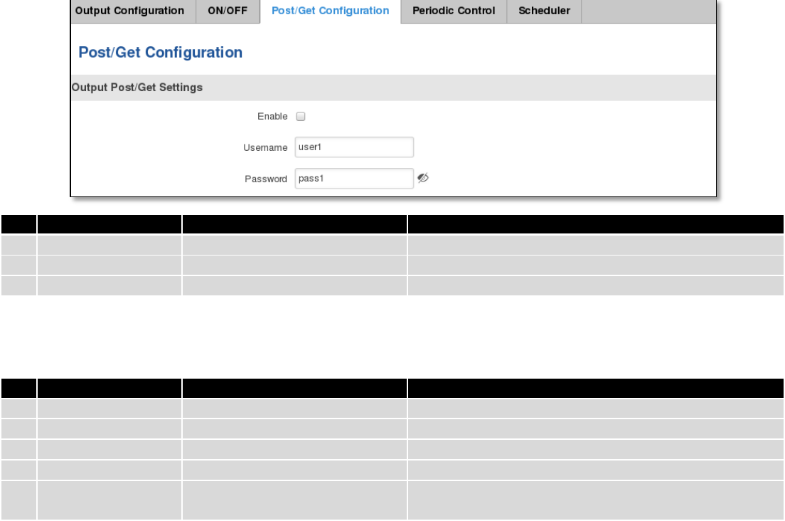
155
9.18.3.3 Post/Get Configuration
Field name
Example
Explanation
1.
Enable
Enable /Disable
Enable POST/GET output functionality
2.
Username
User1
Service user name
3.
Password
Pass1
User password for authentication
9.18.3.4 Syntax of Output HTTP POST/GET string
With Output post/get you can manage only Outputs (Open collector output and Digital relay output).
Field name
Example
Explanation
1.
IP_ADDRESS
192.168.1.1
IP address of your router
2.
action
on and off
Specify the action to be taken
3.
pin
oc and relay
Specify the output
4.
delay (sec)
15
Delay in seconds after which action will be started
5.
time (sec)
10
Time in seconds after which the action will be stopped.
(if action is on, then it will go back to off after *time*)
Please note:
Delay and time parameters can be used together. Example: delay is 10, time is 5, action is „on“. 10 seconds after
command execution output will switch to „on“ (or stay in „on“ state if it‘s already on), then after 5 more seconds it will
switch to off state. Overall command execution time is 15 seconds.
Actions „on“ and „off“ depend on setting „Output configuration in active state“ (on is active state), which can be
set via Services > Input/Output > Output
9.18.3.5 Output HTTP POST/GET string examples
http://192.168.1.1/cgi-bin/output?username=User1&password=Pass1&action=on&pin=relay
http://192.168.1.1/cgi-bin/output?username=User1&password=Pass1&action=on&pin=relay&delay=10
http://192.168.1.1/cgi-bin/output?username=User1&password=Pass1&action=on&pin=relay&time=5
http://192.168.1.1/cgi-bin/output?username=User1&password=Pass1&action=on&pin=relay&delay=15&time=5
http://192.168.1.1/cgi-bin/output?username=User1&password=Pass1&action=off&pin=relay&delay=15&time=5
http://192.168.1.1/cgi-bin/output?username=User1&password=Pass1&action=on&pin=oc
http://192.168.1.1/cgi-bin/output?username=User1&password=Pass1&action=off&pin=oc
9.18.3.6 Periodic Control
Periodic control function allows user to set up schedule by which the outputs are either turned ON or OFF at specific
time.
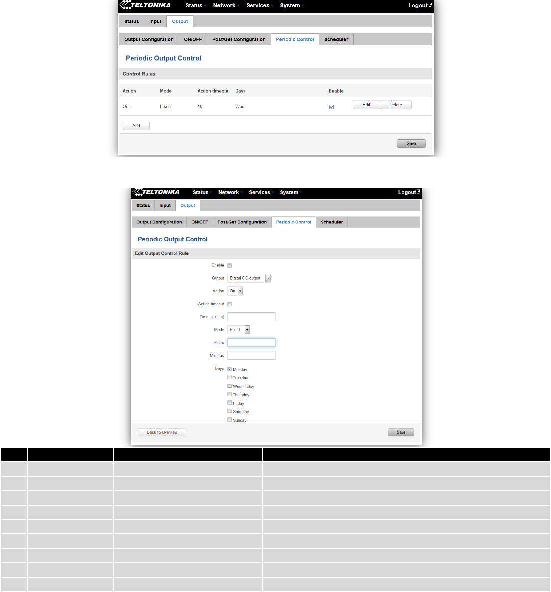
156
After clicking on ADD button (Or Edit, if the rule is already created) you get the second periodic output configuration
page with extra parameters to set.
Field name
Sample
Explanation
1.
Enable
Enable/Disable
Enable this output rule
2.
Output
Digital/Digital isolated/Analog
Specify the output type
3.
Action
On / Off
Specify the action to be taken
4.
Action timeout
Enabled / Disabled
Enable timeout for this rule
5.
Timeout (sec)
10
Specifies after how much time this action should end.
6.
Mode
Fixed / Interval
Specify the mode of output activation
7.
Hours
15
Specify the hour for rule activation
8.
Minutes
25
Specify the minute for rule activation
9.
Days
Monday
Select the week days for rule activation
9.18.3.7 Scheduler
This function allows you to set up the periodical, hourly schedule for the outputs. You can select on which week
days the outputs are going to be on or off.
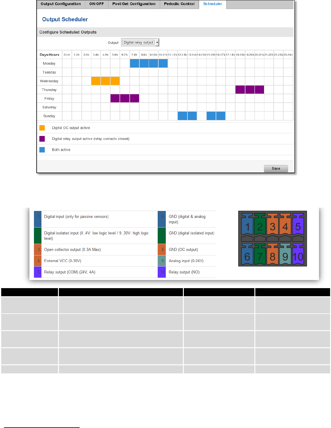
157
9.18.4 Input/Output hardware information
The Input/output (I/O) connector is located in the front panel next to LEDs. Pin-out of the I/O connector:
Type
Description
Ratings
QTY
Input (digital)
Digital non-isolated input for passive
sensors
3V Max
1
Input(digital)
Digital input with galvanic isolation
0..4V – low level
9..30V – high level
1
Input (analog
voltage/current)
Analog input (0-24V/0-20mA)
24V/20mA Max (with
1.2kΩ shunt)
1
Output (Open
collector)
Open collector (OC) output
30V, 0.3A
1
Output (relay)
SPST relay output
24V, 4A
1
9.18.4.1 Digital input for passive sensors
Absolute maximum ratings:

158
Maximum voltage on input pin1 with respect to pin6: 3V
Minimum voltage on input pin1 with respect to pin6: 0V
The input is protected from short positive or negative ESD transients
This input is designed for connecting sensors with passive output (not outputting voltage) such as:
Passive infrared (PIR) sensors for motion detection (sensors with open
collector or relay output are suitable type to use )
Mechanical Switches, pushbuttons
Reed switches, which opens or closes its contacts when magnetic field is
near
Any sensor with open collector or open drain output (use without pull-up resistor)
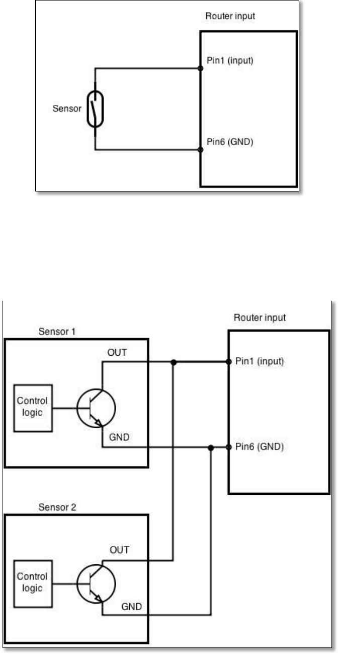
159
Example schematic of using PIR sensors, mechanical switches, reed switches:
Example schematic of connecting multiple sensors with open collector outputs:
Multiple sensors can be connected in parallel like in the schematic below. In this configuration any sensor will
activated the input. The example could be multiple motion sensors located in multiple places. If either of them will
sense motion, the configured event (for e.g. alarm) will be activated. This is suitable when you just need to know that
alarm is triggered but it is not necessary to know which sensor activated an alarm.
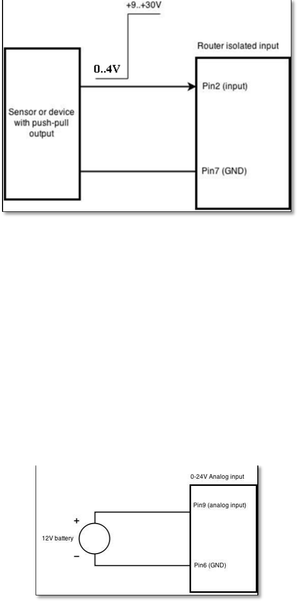
160
9.18.4.2 Digital galvanically isolated input
Sensors with push-pull output stage can be connected to this input. Example of such circuit is shown in the
picture below. The circuit uses optocoupler to isolate the input. In case of the failure at the input, the rest of the circuit
remains safe.
The signal source resistance should be less than 100Ω.
Input voltage levels:
Low level voltage: 0..+4V
High level voltage: +9..30V
Maximum ratings:
Maximum voltage that can be connected to pin2 with respect to pin7 is 30V. Do not exceed this voltage!
The input is protected from reverse voltage down to -200V.
9.18.4.3 Analog input
Analog input is designed to measure analog voltages in the range of 0-24V and convert it to digital domain. This
input can also be used to measure current up to 20mA.
Example of monitoring 12V battery voltage:
When Analog input type is „Analog Current“ a 1.2kΩ resistor shunt must be connected as shown below:
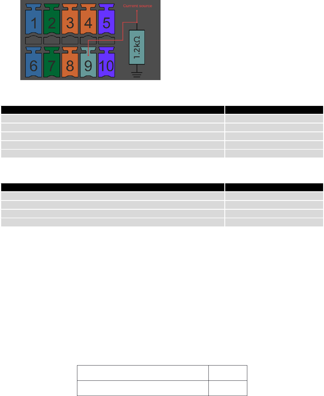
161
Input electrical characteristics:
Parameter
Value
Maximum voltage
24V
Minimum voltage
0V
Resolution
5.859mV
Input low-pass filter cut-off frequency (-3dB)
10Hz
Input resistance (seen between I/O header pins 9 and 6 )
131kΩ
Input accuracy:
Input voltage range, V
Measurement error, %
0 <Vin≤ 1
<20
1 <Vin≤ 2
<10
2 <Vin≤ 5
<5
5 <Vin≤ 24
<3
9.18.4.4 Open collector output
This output can be used to drive external relay. In order for the output to work correctly, external voltage that is
connected to a relay also needs to be connected to I/O header pin 4. There is flyback diode located inside the device to
protect it from spikes occurring when inductive load (relay coil) is suddenly switched off, so connection of the external
diode is not necessary. The output is isolated from the rest of the circuitry using optocoupler. In case of the output
failure, the rest of the circuit will remain protected.
Maximum external DC voltage
30V
Maximum output sink current
0.3A
Example of driving a relay:
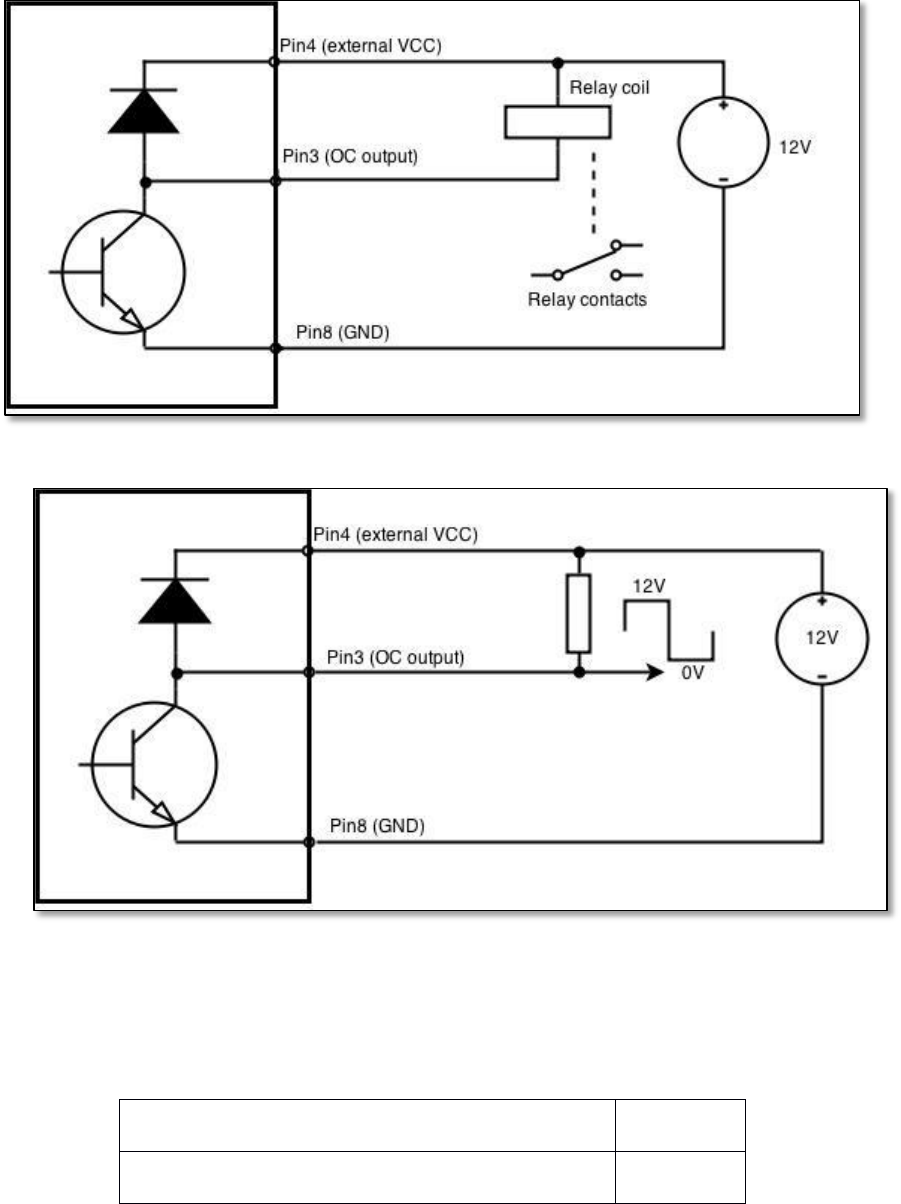
162
Output can be also used to generate signals with desired amplitude. Resistor could be for example 4.7kΩ.
9.18.4.5 Relay output
Relay output has two pins: COM and NO. When the relay is not energized (output not active), these pins are
disconnected. One the relay is energized (output active) these pins are become connected together.Relay output is not
intended to drive AC voltages.
Maximum DC voltage across relay contacts
24V
Maximum relay DC current
4A
Example of connecting alarm siren to the relay output:
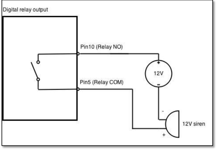
163
9.19 MQTT
MQTT also known as MQ Telemetry Transport is an publish-subscribe based messaging protocol for use on top of
the TCP/IP protocol. It is designed to send short messages from one client (publisher) to another (subscriber) through
the brokers, which are responsible for message delivery to the end point. RUT 9XX routers do support this functionality
via open source Mosquitto broker. The messages are sent in this way: some client (subscriber) subscribes to specific
topic or many of them, and then publisher posts some message to specific topic. The broker then checks who is
subscribed to particular topic and transmits data from publisher to subscriber.
RUT9XX supports some functionality of the MQTT broker and MQTT publisher. The main window of parameters is
presented below. The broker can be enabled by checking Enable and entering the port number on which MQTT broker
should run to. In order to accept connections from WAN interface, Enable Remote Access should be checked also.
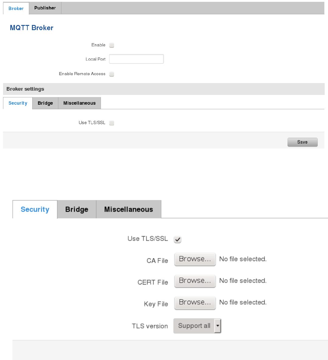
164
In order to use TLS/SSL for connecting clients (subscribers and publishers) to the broker, the one should check
Use TLS/SSL. After that, additional settings will be displayed to the user as shown below. Here the user can upload
certificates, key files and choose TLS version, which will be used for data encryption between broker and clients
(subscribers and publishers)
The MQTT broker also supports option called Bridge. It means, that two brokers can be connected to each other
and share messages. The window of bridge parameters are presented below. There are some mandatory parameters,
like Connection Name, Remote Address and Remote Port. Although connection name is mandatory, it should be set to
value what you like and according to mosquitto’s user manual this option denotes the client ID which will be used when
connecting to remote broker. There are some other parameters. If you would like to known that they mean and how to
use them you should check for mosquito.conf manual page.
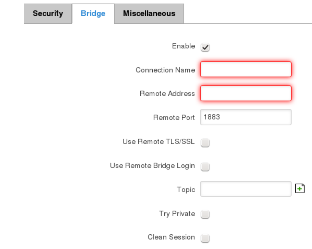
165
,
The last section of parameters is called Miscellaneous. It contains parameters, which does not depend on neither
Security, nor Bridge categories. ACL File denotes access control list file name. The contents of this file are used to control
client access to topics of the broker. The Password File denotes the file, there users and corresponding passwords are
stored. This file is used for user authentication. This option is related to another option called Allow Anonymous. If
Allow Anonymous is unchecked, only users, which exist in password file will be able to connect to the broker. More
about password file can be read on mosquitto configuration manual. The last option is called Persistence, it allows to
save connection, subscription and message data to the disk, otherwise, the data is stored in memory only.
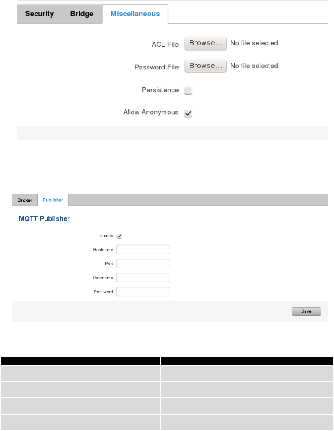
166
It is possible to configure some sort of MQTT publisher. It is not simple publisher, but publisher, which publishes
some system parameters to the broker. The publisher configuration window has few fields, like hostname and port of
the broker to connect. Username and password fields are used for authentication. If these fields are left empty, no
authentication is performed.
The full list of system parameters, which can be published, are described below.
Parameter name
Parameter description
temperature
Get temperature of the module in 0.1 degrees Celcium
operator
Get current operator’s name
signal
Get signal strength in dBm
network
Get current network type (2G, 3G, 4G, etc’)
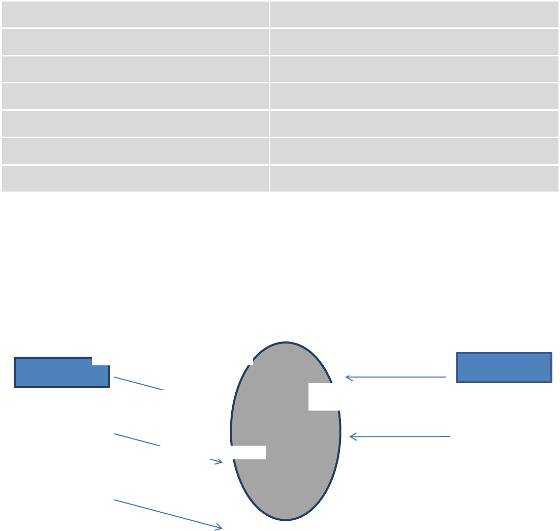
167
connection
Check if data connection is available
wan
Get WAN’s IP address
uptime
Get system uptime in seconds
name
Get router’s name
digital1
Get value of digital input no. 1
digital2
Get value of digital input no. 2
analog
Get value of analog input
In order system to work, MQTT broker should be configured in advance. You can use the broker, which is installed inside
the router, or the broker in the other location. The publisher operates according to the scheme presented below. In the
scheme the client tries to subscribe information about router’s uptime. To achieve this multiple commands between
client and publisher are being sent.
In general publisher works in such a way: connects to the broker and subscribes to the topics router/get and
get/<SERIAL>/command, there <SERIAL> denotes serial number of the router which is currently run publisher. The client
then sends message id to the topic router/get. The following message is received by the publisher, since it is subscribed
to that topic. Then the publisher sends response with its serial number to the topic router/id. Now the client knows that
publisher with some serial number exist. It means, that client can send message with parameter name from the list as a
message to the topic get/<SERIAL>/command to the broker. The message will be received only by the subscriber, which
has the same SERIAL number mentioned in the topic. Now the publisher can send back a response with
router/<SERIAL>/parameter_name topic and message with a value of requested parameter. It should be noted, that
according to MQTT protocol, the topic names are case-sensitive, for example topic router is not the same as topic
RoUtEr.
Publisher
Subscribe router/get
Subscribe
get/01234567/command
Publish router/get
id
Publish router/id
01234567
Publish get/01234567/command
uptime
Broke
r
Client
Publish router/01234567/uptime 15248
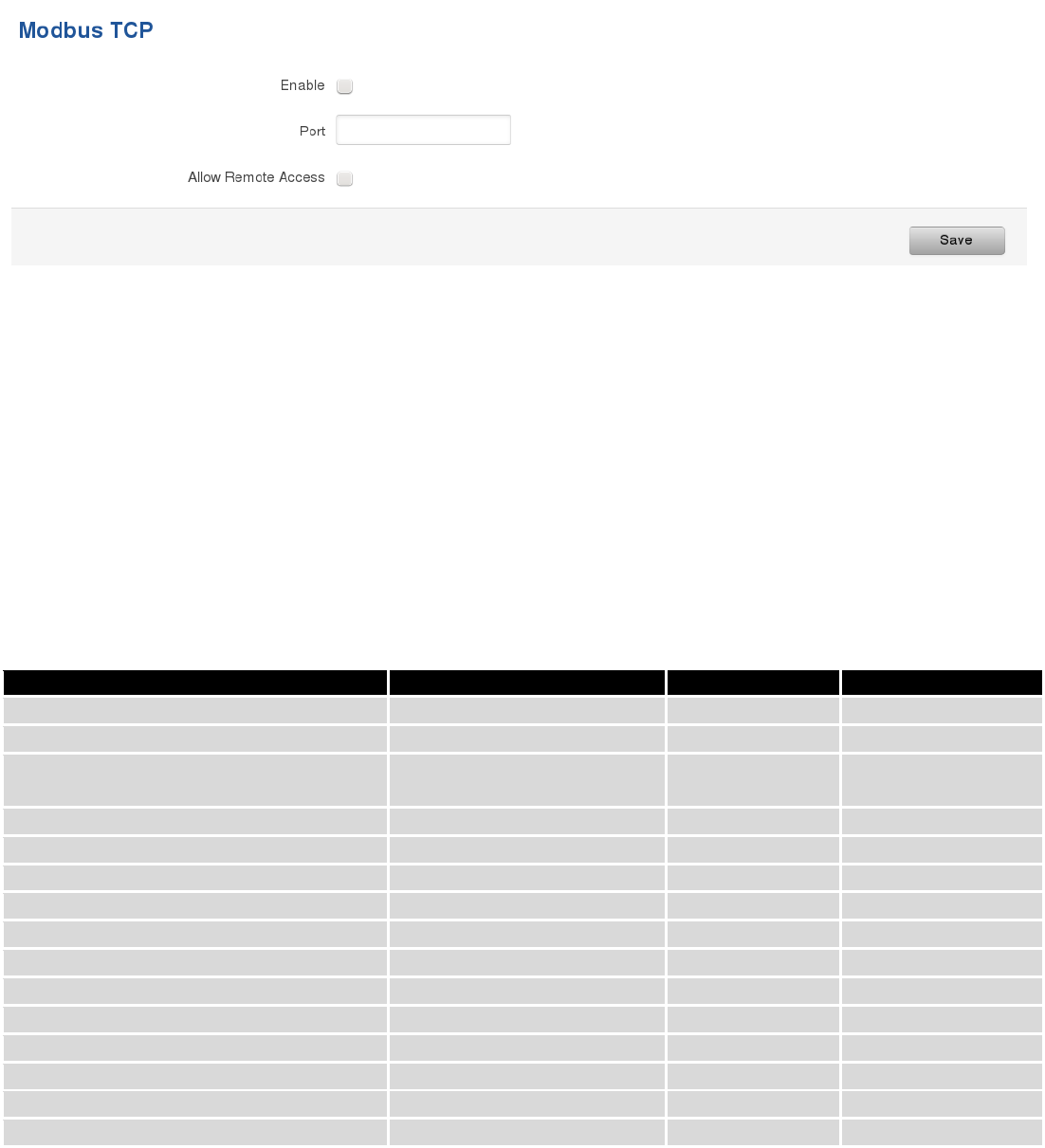
168
9.20 Modbus TCP interface
Modbus TCP interface allows the user to set or get some parameters like module temperature, signal strength,
etc. from the router. In other words, Modbus TCP allows to control routers behavior and get its status information. To
use Modbus TCP capabilities this feature must be enabled by navigating to Services-Modbus. After “Save” button is
pressed, the Modbus daemon will be launched on selected port of the system. Modbus daemon acts as slave device
that means, it accepts connection from the master (client) and sends out a response or sets some system related
parameter. By the default Modbus will only accept connections through LAN interface. In order to accept connections
through WAN interface also, Allow Remote Access must be checked.
To obtain some parameter from the system, the read holding registers command is used. The register number
and corresponding system values are described below. Each register contains 2 bytes. For simplification the number of
registers for storing numbers is 2, while for storing text information the number of registers is 16.
Required value
Representation
Register number
Number of registers
System uptime
32 bit unsigned integer
1
2
GSM signal strength (dBm)
32 bit integer
3
2
System temperature in 0.1 degrees
Celcium
32 bit integer
5
2
System hostname
Text
7
16
GSM operator name
Text
23
16
Router serial number
Text
39
16
Router MAC address
Text
55
16
Router name
Text
71
16
Current SIM card
Text
87
16
Network registration
Text
103
16
Network type
Text
119
16
Digital input 1
32 bit integer
135
2
Digital input 2
32 bit integer
137
2
Current WAN IP address
32 bit unsigned integer
139
2
Analog input
32 bit integer
141
2
The Modbus daemon also supports setting of some system parameters. For this task write holding register
command is used. System related parameters and how to use them are described below. The register number refers to
the register number where to start write required values. All commands, except “Change APN” accepts only one input
parameter. For the APN the number of input registers may vary. The very first byte of APN command denotes a number

169
of SIM card for which set the APN. This byte should be set to 1 (in order to change APN for SIM card number 1) or to 2
(in order to change APN for SIM card number 2).
Value to set
Description
Register number
Register value
Digital output 1 (on/off)
Change the state of the digital output
number 1
201
1/0
Digital output 2 (on/off)
Change the state of the digital output
number 2
202
1/0
Switch WiFi (on/off)
Allows to switch WiFi on or off
210
1/0
Switch mobile data connection
(on/off)
Turns on or off mobile data
connection
211
1/0
Switch SIM card (SIM1, SIM2,
SIM1->SIM2 and SIM2->SIM1)
Allows to change SIM card in use, 3
possible options are supported
212
0/1/2
Change APN
Allows to change APN
213
APN code
Reboot
Reboots a router
220
1
10 System
10.1 Configuration Wizard
The configuration wizard provides a simple way of quickly configuring the device in order to bring it up to basic
functionality. The wizard is comprised out of 4 steps and they are as follows:
Step 1 (General change)
First, the wizard prompts you to change the default password. Simply enter the same password into both
Password and Confirmation fields and press Next.
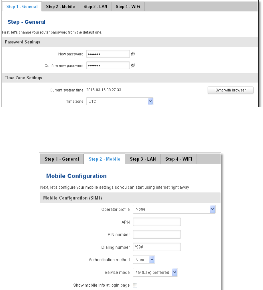
170
Step 2 (Mobile Configuration)
Next we have to enter your mobile configuration. On a detailed instruction on how this should be done see the
Mobile section under Network
Step 3 (LAN)
Next, you are given the chance to configure your LAN and DHCP server options. For a detailed explanation see
LAN under Network.
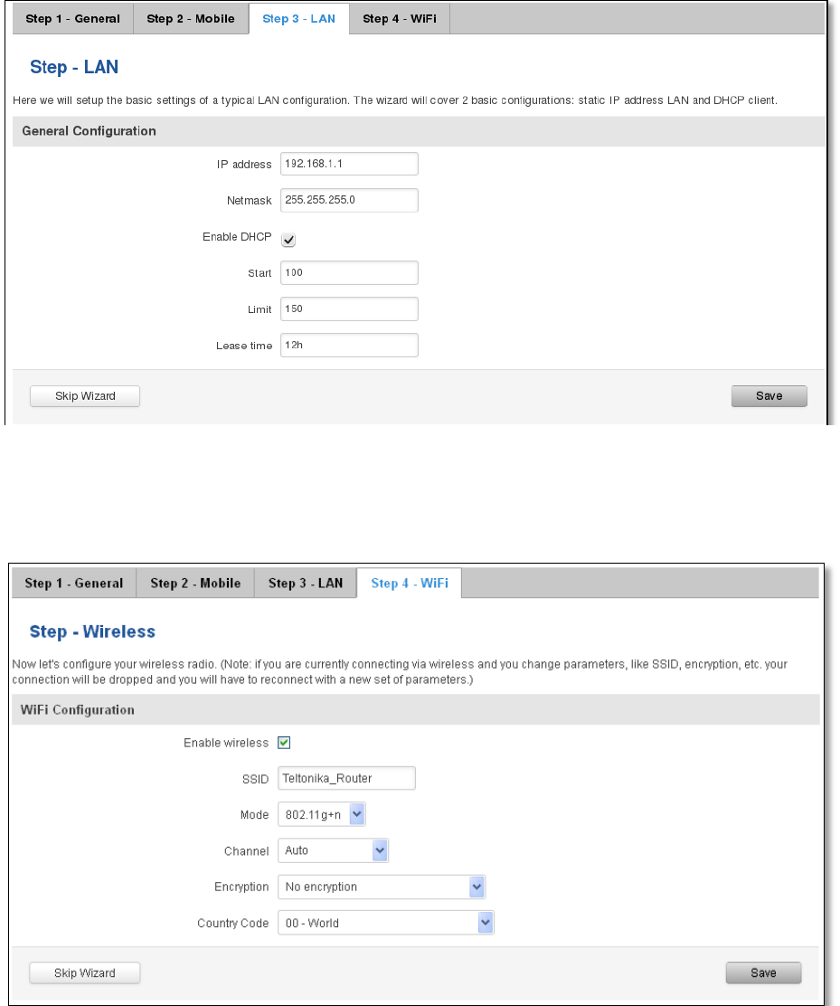
171
Step 4 (Wi-Fi)
The final step allows you to configure your wireless settings in order to set up a rudimentary Access Point.
When you’re done with the configuration wizard, press Save.
10.2 Profiles
Router can have 5 configuration profiles, which you can later apply either via WebUI or via SMS. When you add
New Profile, you save current full configuration of the router. Note: profile names cannot exceed 10 symbols.
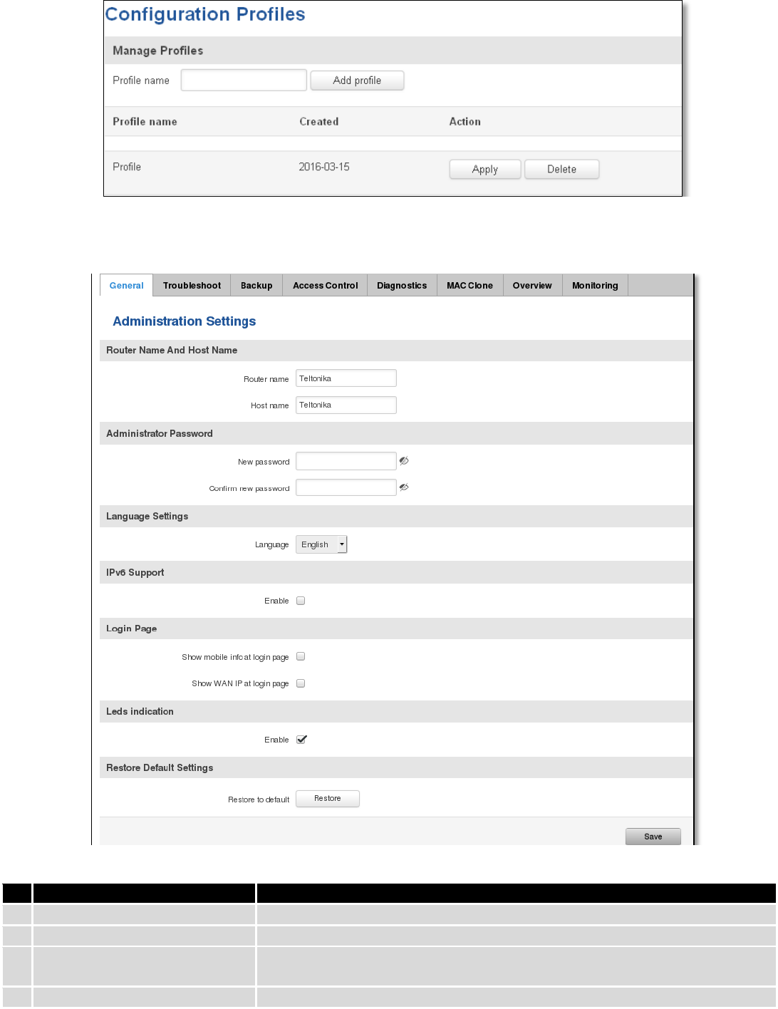
172
10.3 Administration
10.3.1 General
Field name
Explanation
1.
Router name
Enter your new router name.
2.
Host name
Enter your new host name
3.
New Password
Enter your new administration password.
Changing this password will change SSH password as well.
4.
Confirm new password
Re-enter your new administration password.
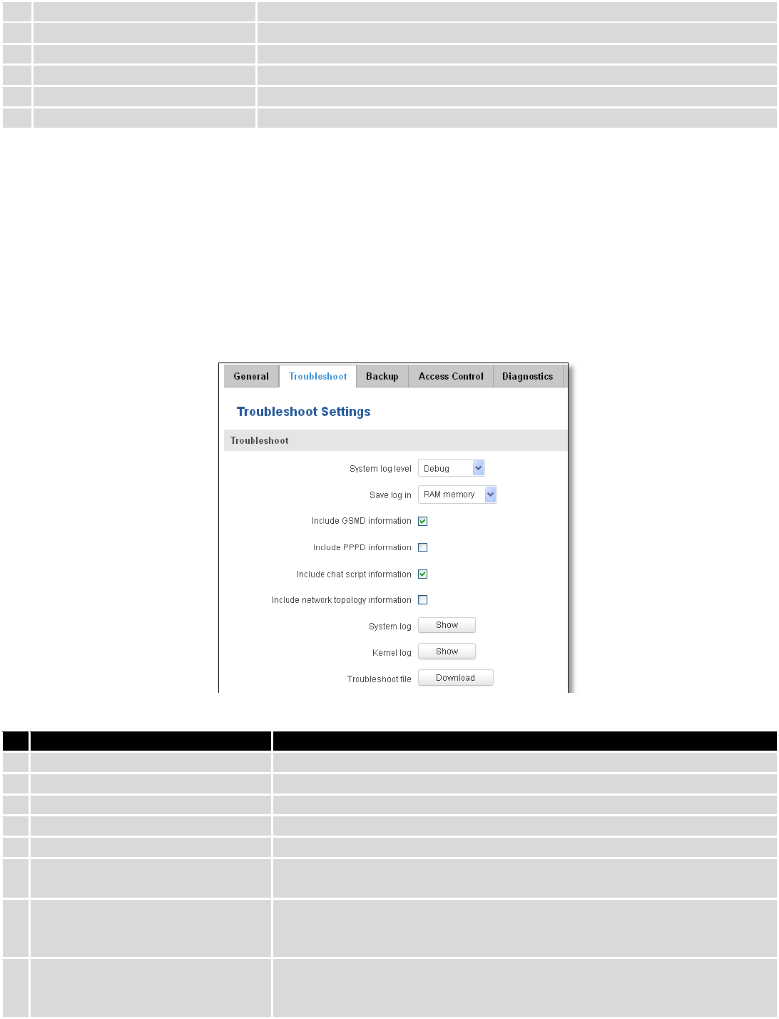
173
5.
Language
Website will be translated into selected language.
6.
IPv6 support
Enable IPv6 support on router
7.
Show mobile info at login page
Show operator and signal strength at login page.
8.
Show WAN IP at login page
Show WAN IP at login page.
9
On/Off LEDs
If uncheck, all routers LEDs are off.
10
Restore to default
Router will be set to factory default settings
Important notes:
The only way to gain access to the web management if you forget the administrator password is to reset the
device factory default settings. Default administrator login settings are:
User Name: admin
Password: admin01
10.3.2 Troubleshoot
Field name
Explanation
1.
System log level
Debug level should always be used, unless instructed otherwise.
2.
Save log in
Default RAM memory should always be used unless instructed otherwise.
3.
Include GSMD information
Default setting – enabled should be used, unless instructed otherwise.
4.
Include PPPD information
Default setting – disabled should be used, unless instructed otherwise.
5.
Include Chat script information
Default setting – enabled should be used, unless instructed otherwise.
6.
Include network topology
information
Default setting – disabled should be used, unless instructed otherwise.
7.
System Log
Provides on-screen System logging information. It does not, however,
substitute troubleshooting file that can be downloaded from System ->
Backup and Firmware menu.
8.
Kernel Log
Provides on-screen Kernel logging information. It does not, however,
substitute troubleshooting file that can be downloaded from System ->
Backup and Firmware menu.
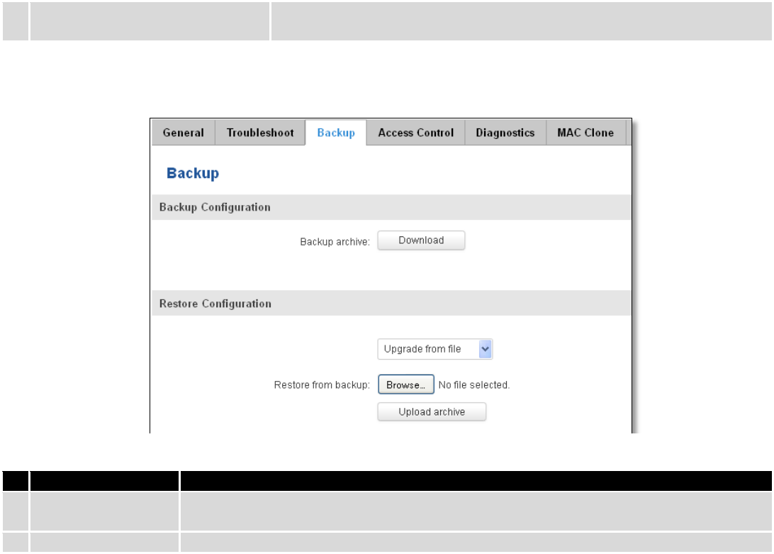
174
9.
Troubleshoot file
Downloadable archive, that contains full router configuration and all System
log files.
10.3.3 Backup
Field name
Explanation
1.
Backup archive
Download current router settings file to personal computer. This file can be loaded to
other RUT955 with same Firmware version in order to quickly configure it.
2.
Restore from backup
Select, upload and restore router settings file from personal computer.
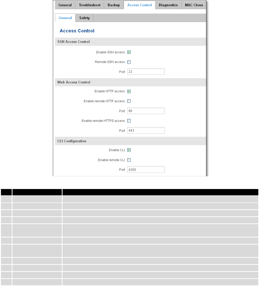
175
10.3.3.1 Access control
10.3.3.1.1 General
Field name
Explanation
1.
Enable SSH access
Check box to enable SSH access.
2.
Remote SSH access
Check box to enable remote SSH access.
3.
Port
Port to be used for SSH connection
4.
Enable HTTP access
Enables HTTP access to router
5.
Enable remote HTTP
access
Enables remote HTTP access to router
6.
Port
Port to be used for HTTP communication
7.
Enable remote
HTTPS access
Enables remote HTTPS access to router
8.
Port
Port to be used for HTTPS communication
9.
Enable CLI
Enables Command Line Interface
10.
Enable remote CLI
Enables remote Command Line Interface
11.
Port
Port to be used for CLI communication
Note: The router has 2 users: “admin” for WebUI and “root” for SSH. When logging in via SSH use “root”.
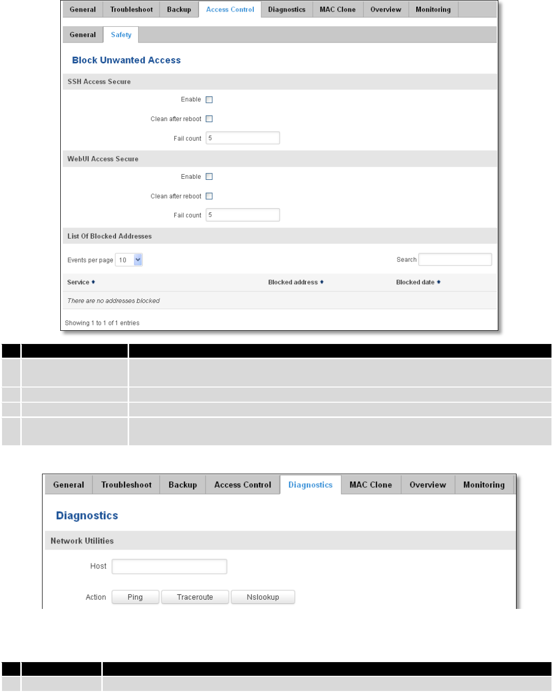
176
10.3.3.1.2 Safety
Field name
Explanation
1.
SSH access secure
enable
Check box to enable SSH access secure functionality.
2.
Clean after reboot
If check box is selected – blocked addresses are removed after every reboot.
3.
Fail count
Specifies maximum connection attempts count before access blocking.
4.
WebUI access
secure enable
Check box to enable secure WebUI access.
10.3.4 Diagnostics
Field name
Explanation
1.
Host
Enter server IP address or hostname.
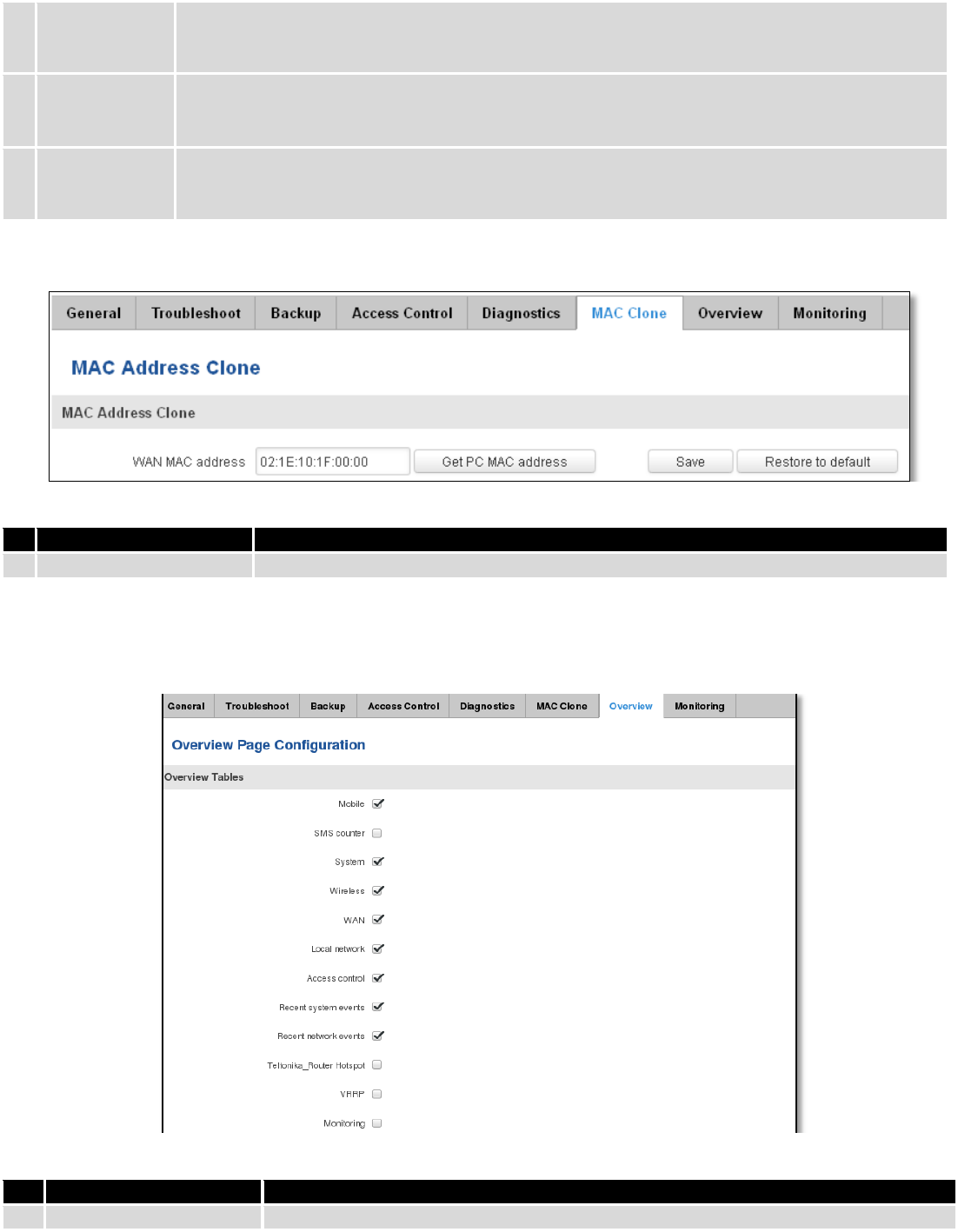
177
2.
Ping
Utility used to test the reach ability of a host on an Internet IP network and to measure the
round-trip time for messages sent from the originating host to a destination server. Server echo
response will be shown after few seconds if server is accessible.
3.
Traceroute
Diagnostics tool for displaying the route (path) and measuring transit delays of packets across an
Internet IP network. Log containing route information will be shown after few seconds.
4.
Nslookup
Network administration command-line tool for querying the Domain Name System (DNS) to
obtain domain name or IP address mapping or for any other specific DNS record. Log containing
specified server DNS lookup information will be shown after few seconds.
10.3.5 MAC Clone
Field name
Explanation
1.
WAN MAC address
Enter new WAN MAC address.
10.3.6 Overview
Select which information you want to get in Overview window (Status -> Overview).
Field name
Explanation
1.
Mobile
Check box to show Mobile table in Overview page
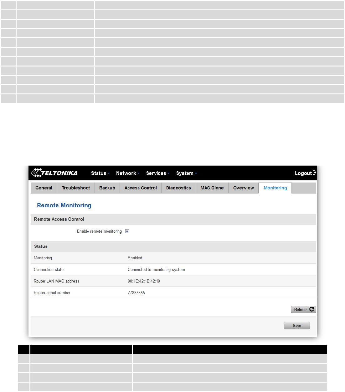
178
2.
SMS counter
Check box to show SMS counter table in Overview page
3.
System
Check box to show System table in Overview page
4.
Wireless
Check box to show Wireless table in Overview page
5.
WAN
Check box to show WAN table in Overview page
6.
Local network
Check box to show Local network table in Overview page
7.
Access control
Check box to show Access control table in Overview page
8.
Recent system events
Check box to show Recent system events table in Overview page
9.
Recent network events
Check box to show Recent network events table in Overview page
10.
<Hotspot name> Hotspot
Check box to show Hotspot instance table in Overview page
11.
VRRP
Check box to show VRRP table in Overview page
12.
Monitoring
Check box to show Monitoring table in Overview page
10.3.7 Monitoring
Monitoring functionality allows your router to be connected to Remote Monitoring System. Also MAC
address and router serial numbers are displayed for convenience in this page, because they are needed when
adding device to monitoring system.
Field name
Explanation
1.
Enable remote monitoring
Check box to enable/disable remote monitoring
2.
Monitoring
Shows monitoring status.
3.
Router LAN MAC address
MAC address of the Ethernet LAN ports
4.
Router serial number
Serial number of the device
10.4 User scripts
Advanced users can insert their own commands that will be executed at the end of booting process.
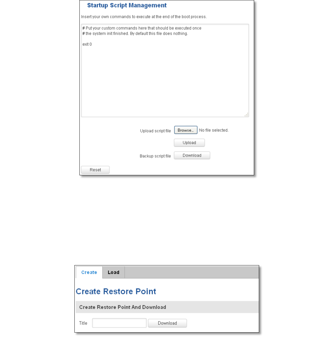
179
In Script Management window is shown content of a file /etc/rc.local. This file is executed at the end of startup,
executing the line: sh /etc/rc.local In this script is needed to use sh (ash) commands. It should be noted, that this is
embedded device and sh functionality is not full.
10.5 Restore point
10.5.1 Restore point create
Allow to create firmware restore points with all custom configurations. You can download created restore points
to your computer.
10.5.2 Restore point load
Allow to restore configuration from previously saved restore point. You can upload restore point from your
computer.
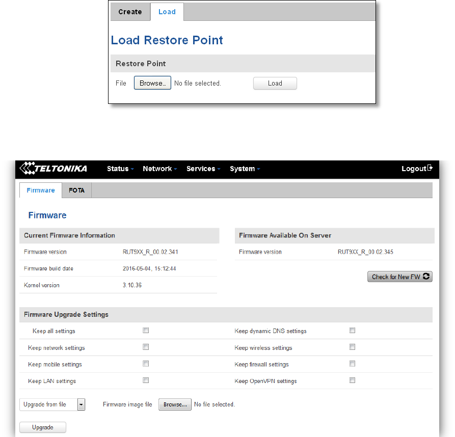
180
10.6 Firmware
10.6.1 Firmware
Keep all settings – if the check box is selected router will keep saved user configuration settings after firmware
upgrade. When check box is not selected all router settings will be restored to factory defaults after firmware upgrade.
When upgrading firmware, you can choose settings that you wish to keep after the upgrade. This function is useful
when firmware is being upgraded via Internet (remotely) and you must not lose connection to the router afterwards.
FW image – router firmware upgrade file.
Warning: Never remove router power supply and do not press reset button during upgrade process! This would
seriously damage your router and make it inaccessible. If you have any problems related to firmware upgrade you
should always consult with local dealer.