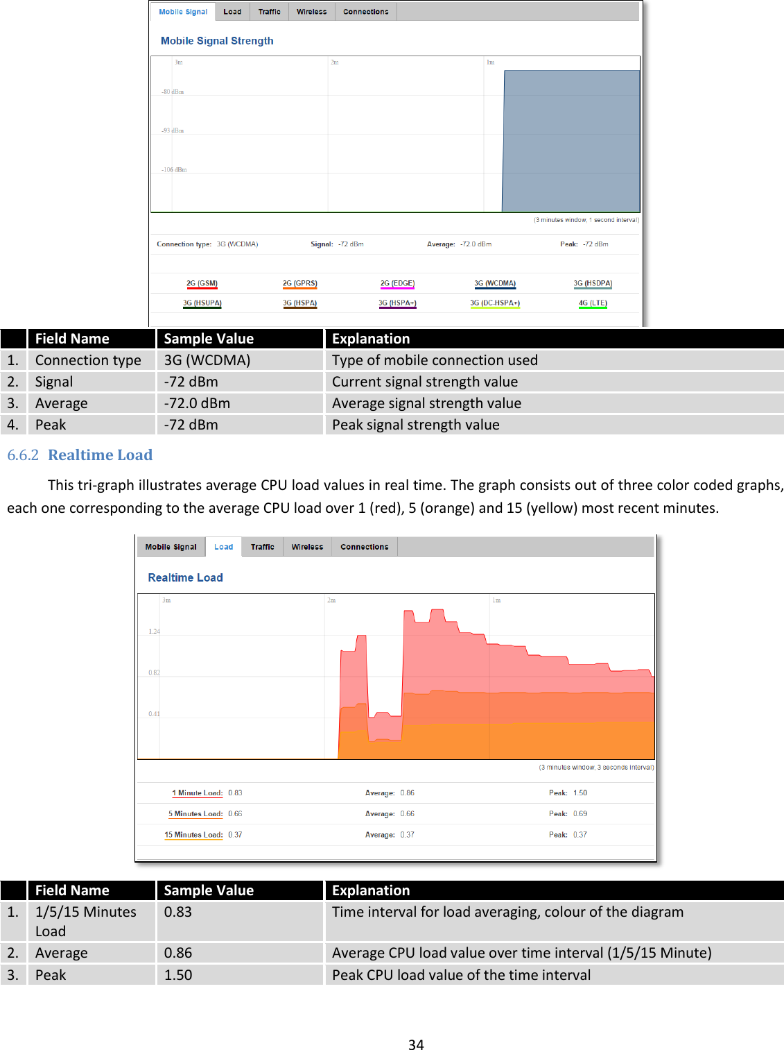
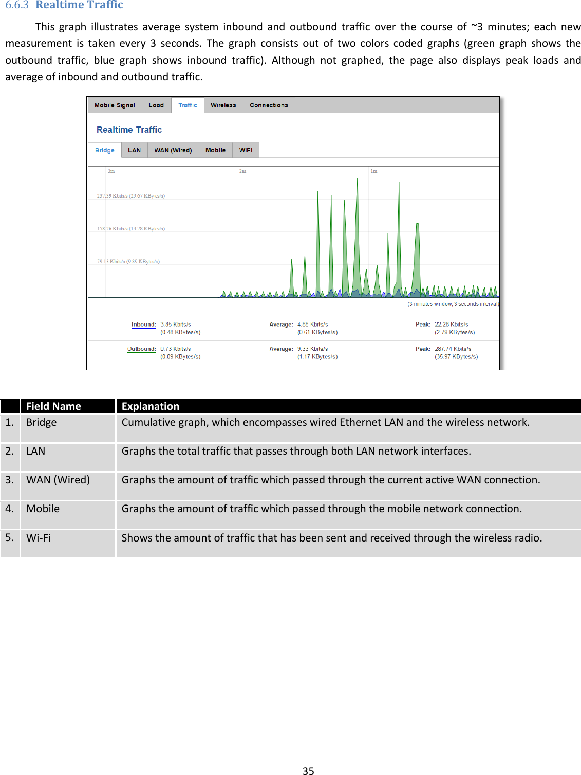
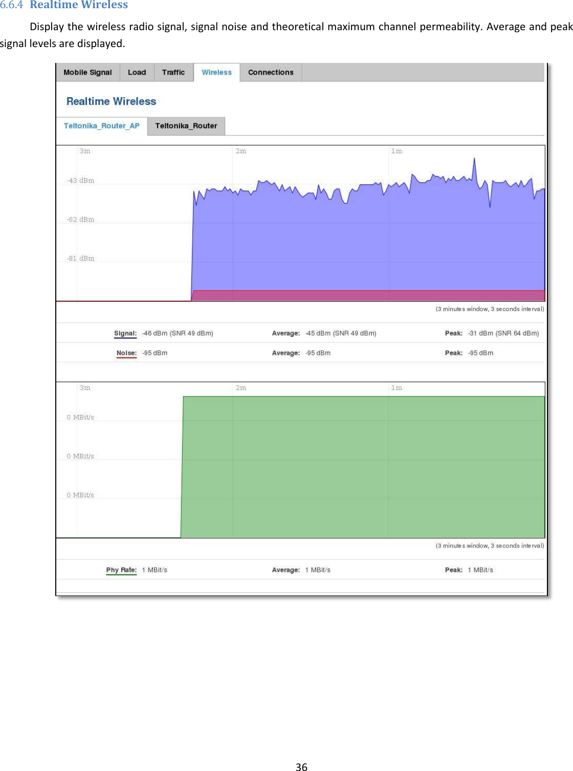
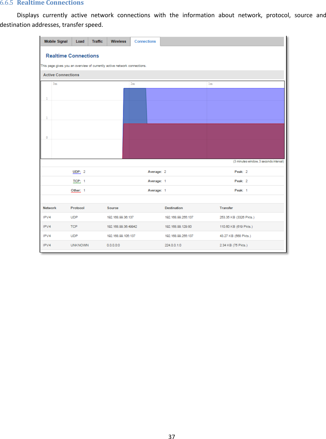
UAB Teltonika RUT955A GPS Tracker User Manual 1
UAB Teltonika GPS Tracker 1
UserManual.wiki
>
UAB Teltonika
>
RUT955A User Manual
>
User Manual 1
Contents
1.
User Manual 1
2.
User Manual 2
3.
User Manual 3
4.
User Manual - Regulatory Guide
User Manual 1
Navigation menu
Upload a User Manual
Namespaces
Wiki Guide
HTML
PDF
Info
Views
User Manual
Discussion / Help
Navigation


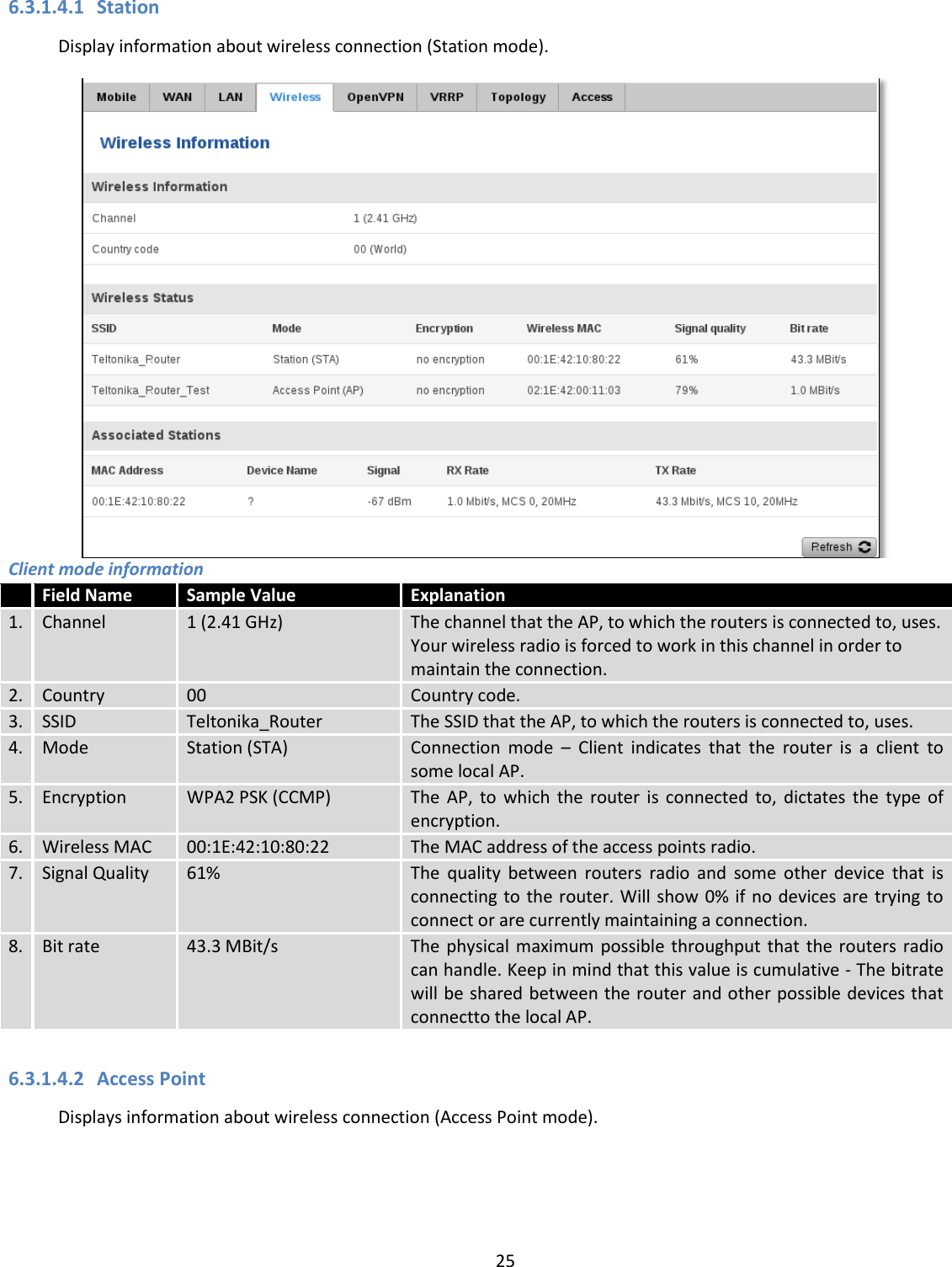
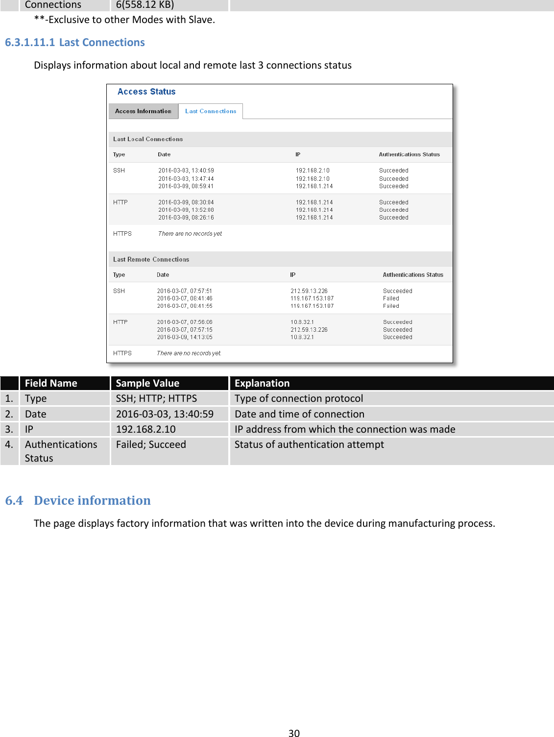
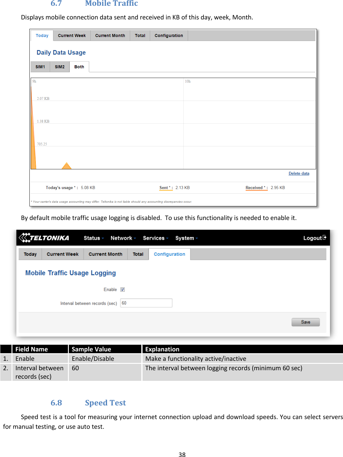
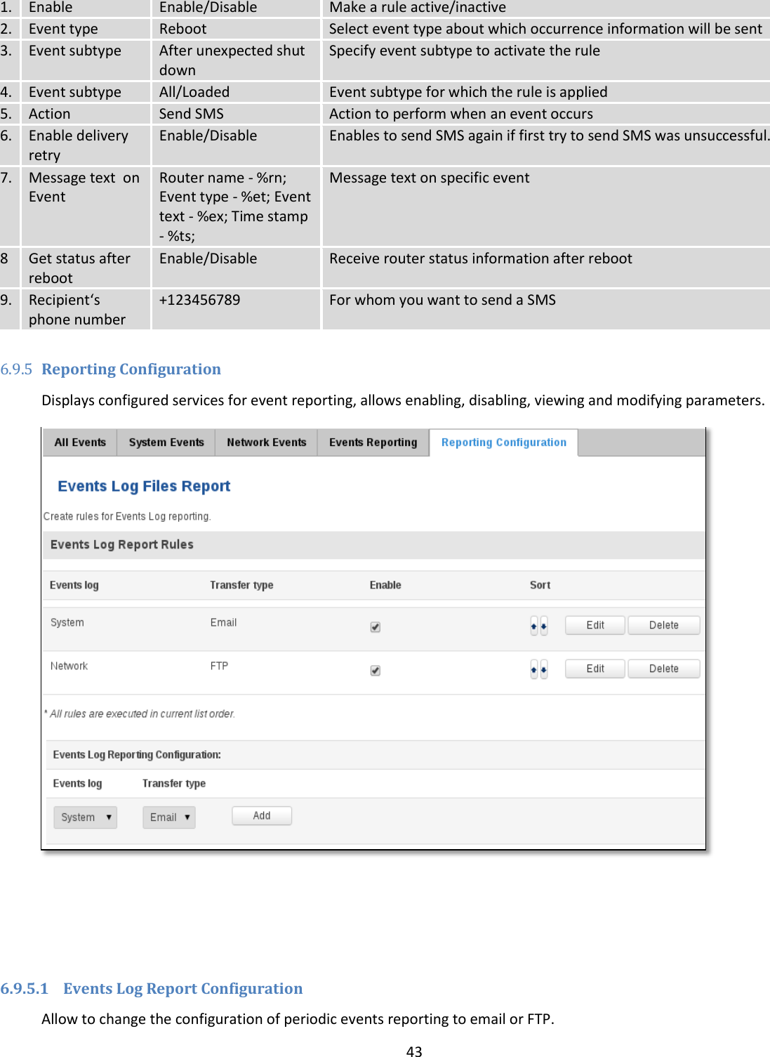
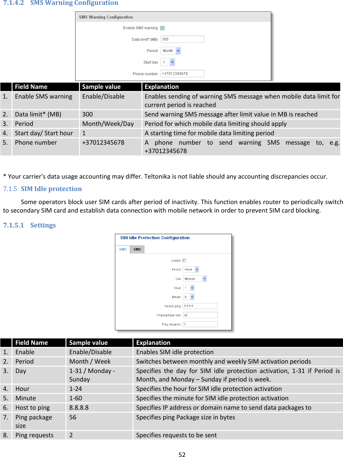
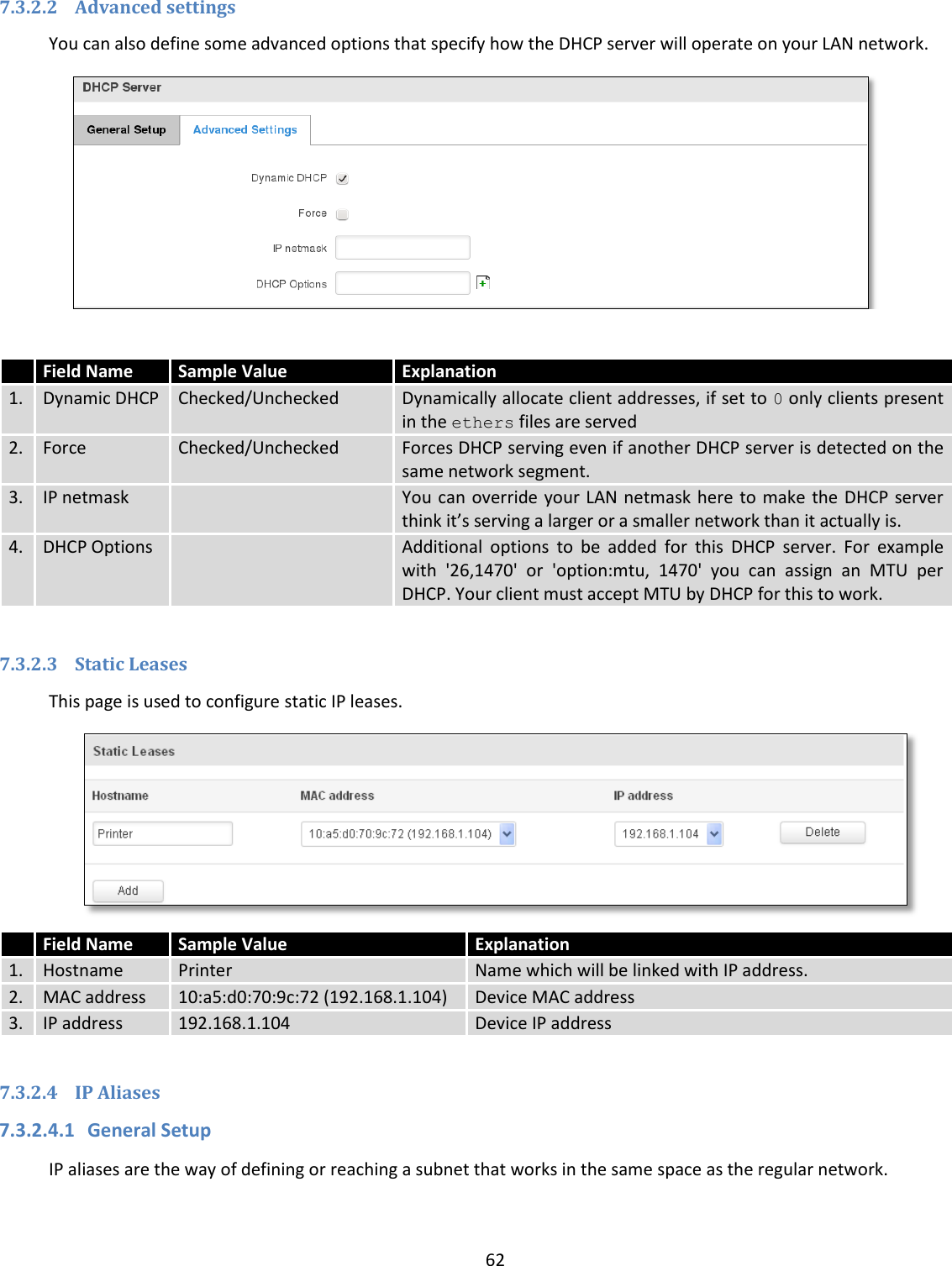
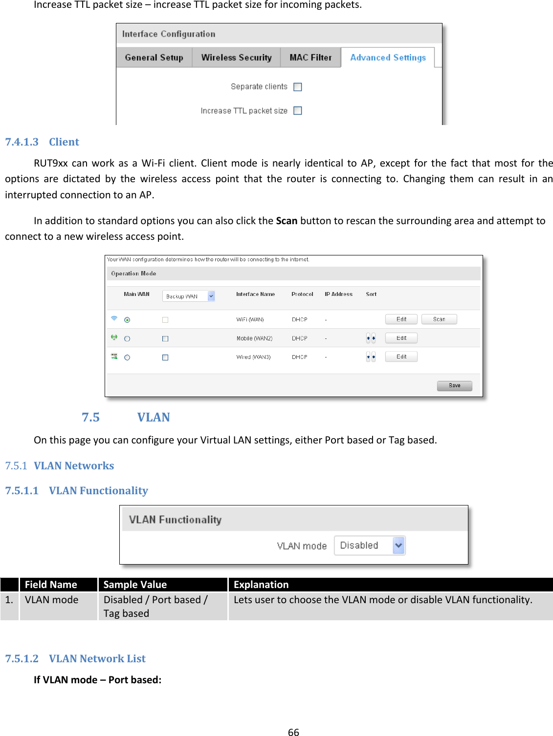
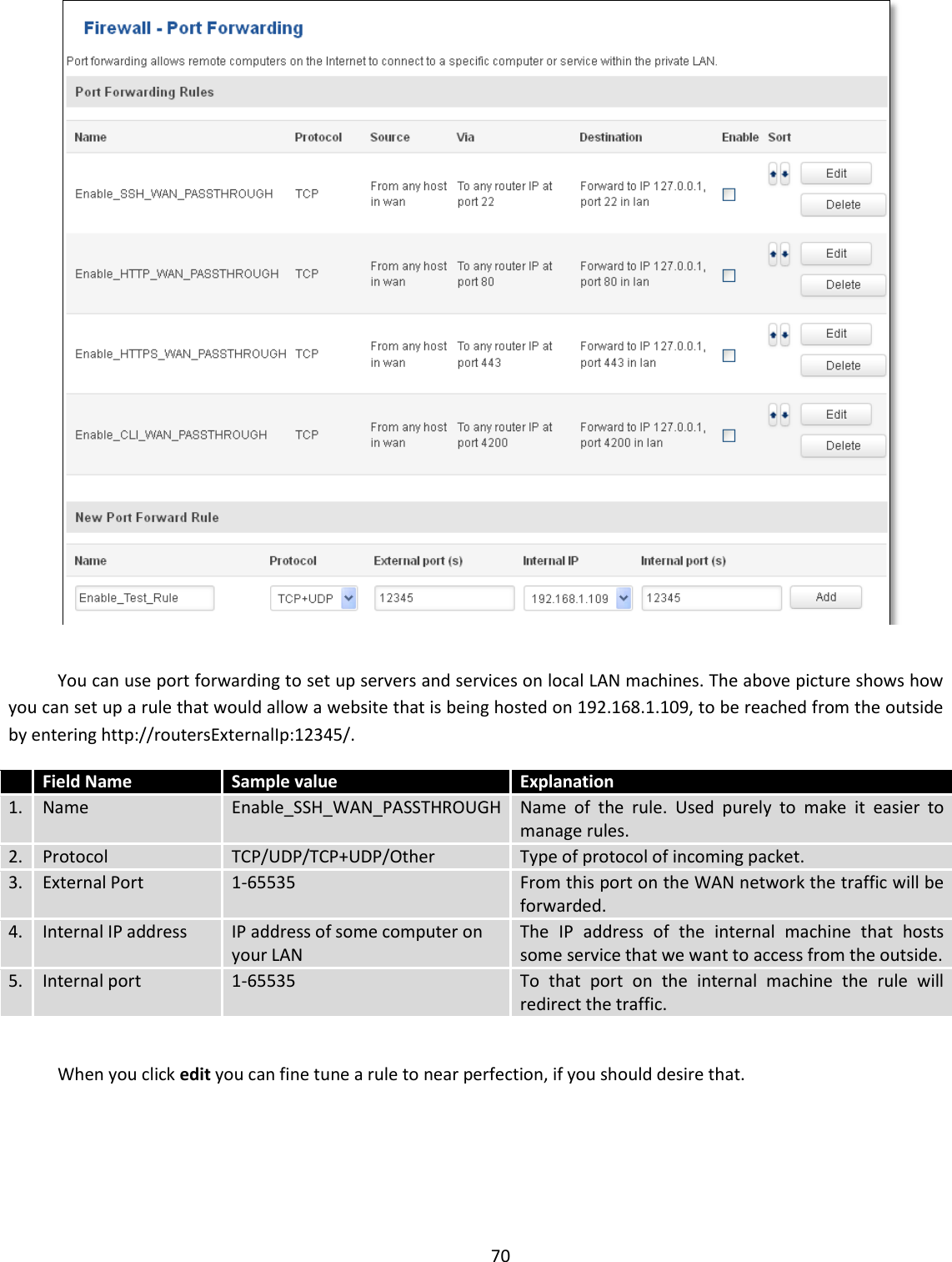
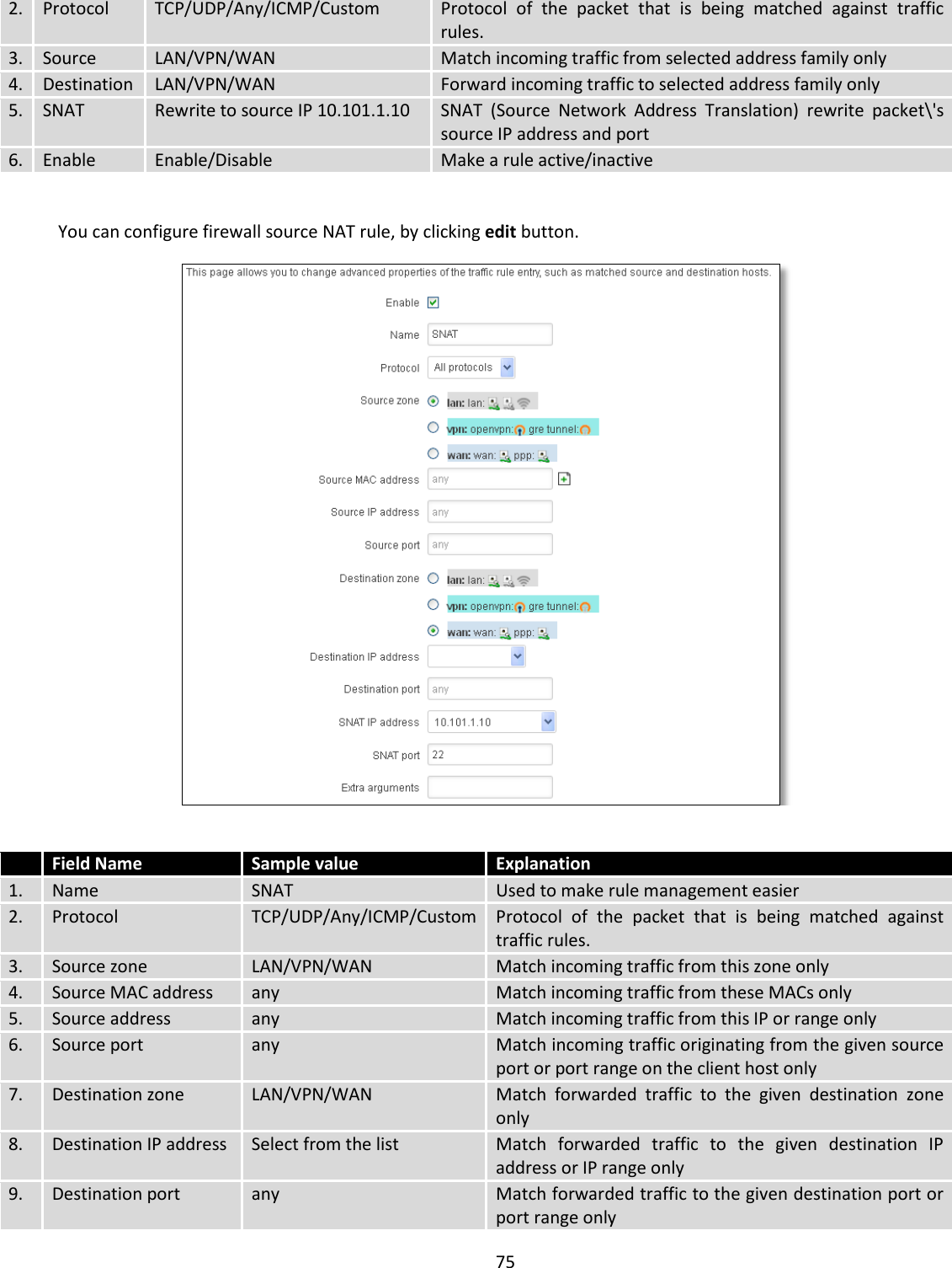
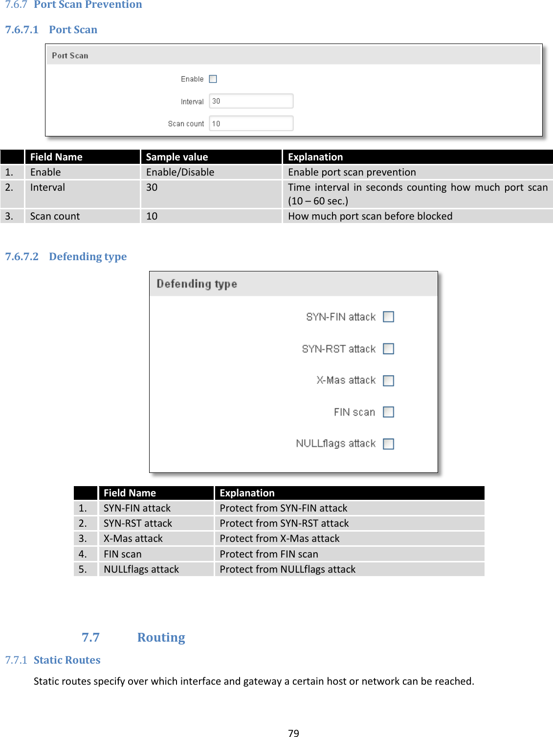
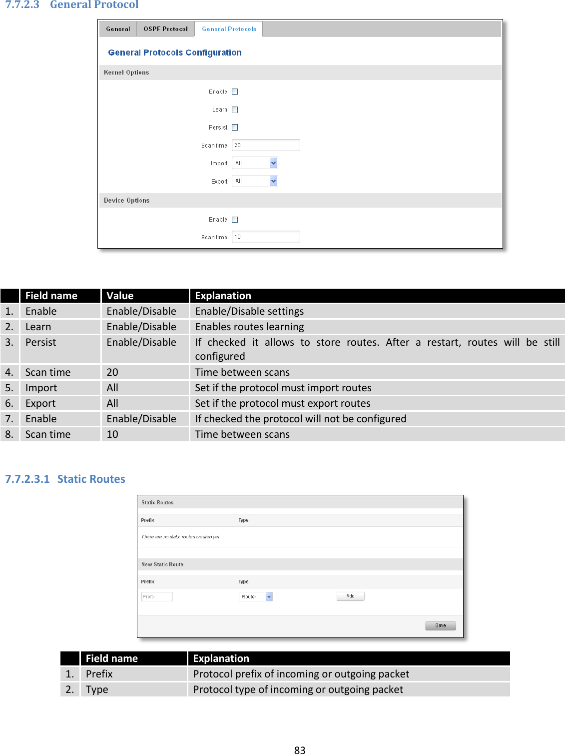
![21 System explanation: Field Name Sample value Explanation 1. Router Name RUT955 Name of the router (hostname of the routers system). Can be changed in System -> Administration. 2. Host name Teltonika-RUT955.com Indicates how router will be seen by other devices on the network. Can be changed in System -> Administration. 3. Router Model Teltonika RUT955 LTE Routers model. 4. Firmware Version RUT9XX_R_00.02.376 Shows the version of the firmware that is currently loaded in the router. Newer versions might become available as new features are added. Use this field to decide whether you need a firmware upgrade or not. 5. Kernel Version 3.10.36 The version of the Linux kernel that is currently running on the router. 6. Local Time 2016-05-24, 11:02:39 Shows the current system time. Might differ from your computer, because the router synchronizes it's time with an NTP server.Format [year-month-day, hours:minutes:seconds]. 7. Uptime 0d 0h 44m 1s (since 2016-05-24, 10:19:03) Indicates how long it has been since the router booted up. Reboots will reset this timer to 0.Format *day’s hours minutes seconds (since year-month-day, hours: minutes: seconds)]. 8. Load Average 1 min: 88%; 5 mins: 73%; 15 mins: 42% Indicates how busy the router is. Let's examine some sample output: "1 min: 88%, 5 mins: 73%, 15 mins: 42%". The first number mean past minute and second number means that in the past minute there have been, on average, 88% processes running or waiting for a resource. 9. Temperature 34.9° C Device’s temperature Memory explanation: Field Name Sample Value Explanation 1. Free 84584 kB /126556 kB (66%) The amount of memory that is completely free. Should this rapidly decrease or get close to 0, it would indicate that the router is running out of memory, which could cause crashes and unexpected reboots.](https://usermanual.wiki/UAB-Teltonika/RUT955A.User-Manual-1/User-Guide-4043741-Page-21.png)
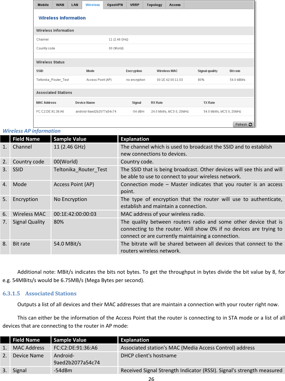
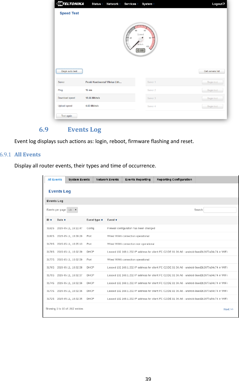
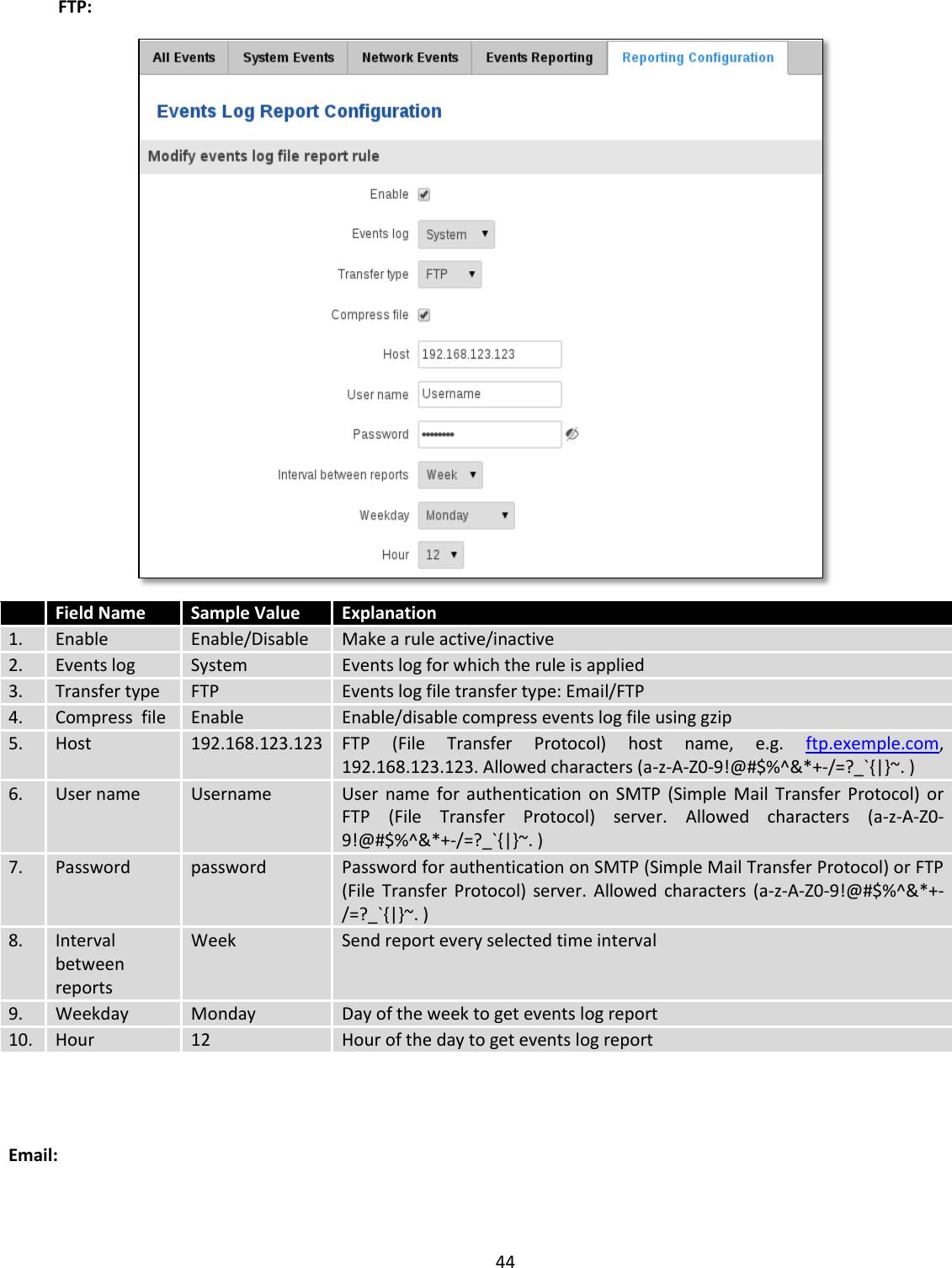
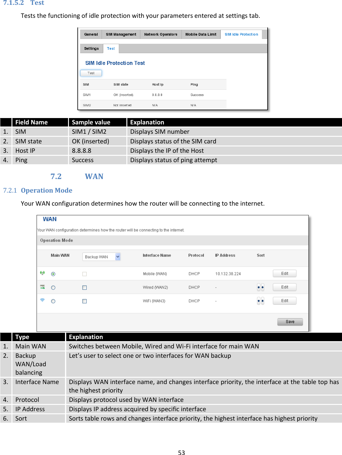
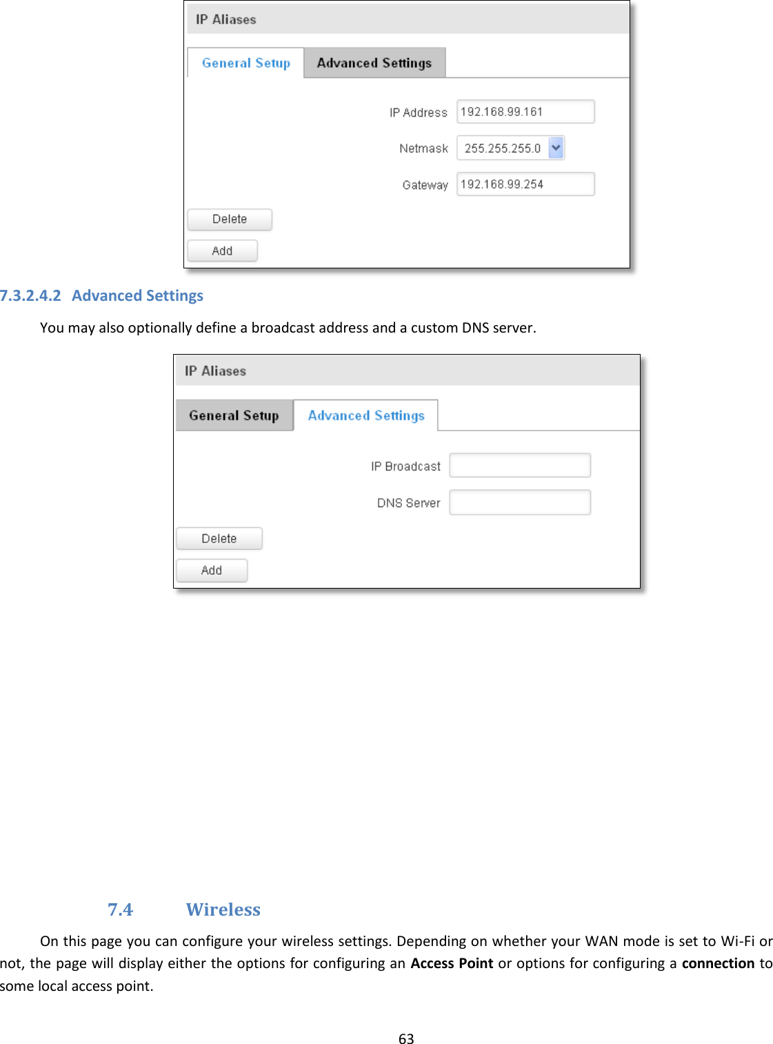
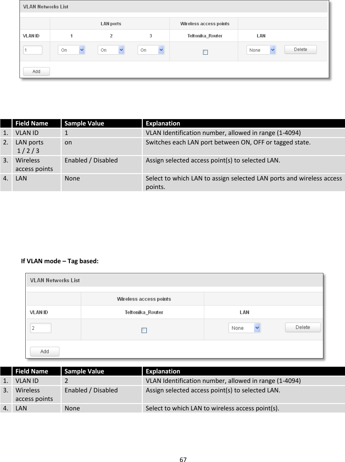
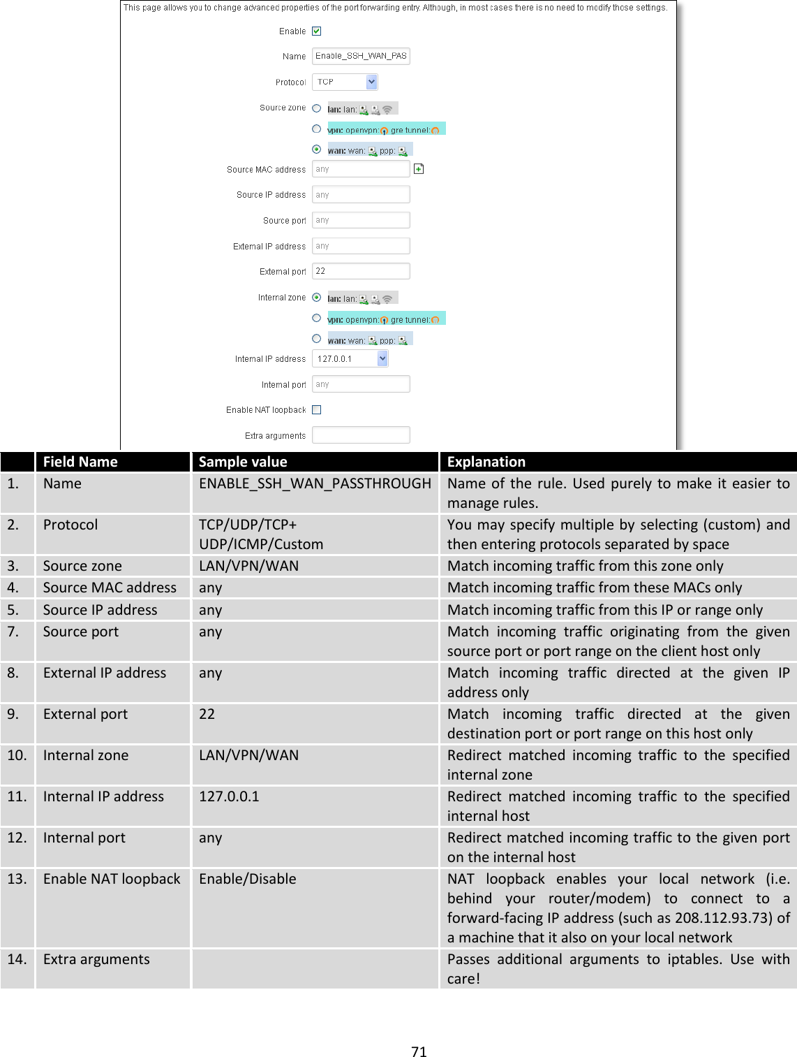
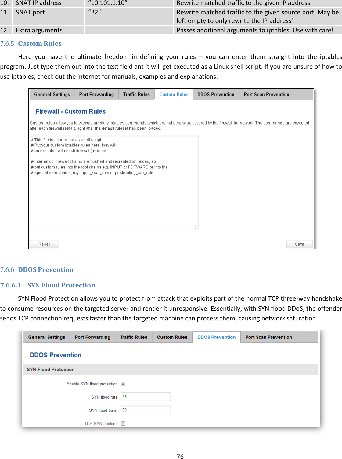
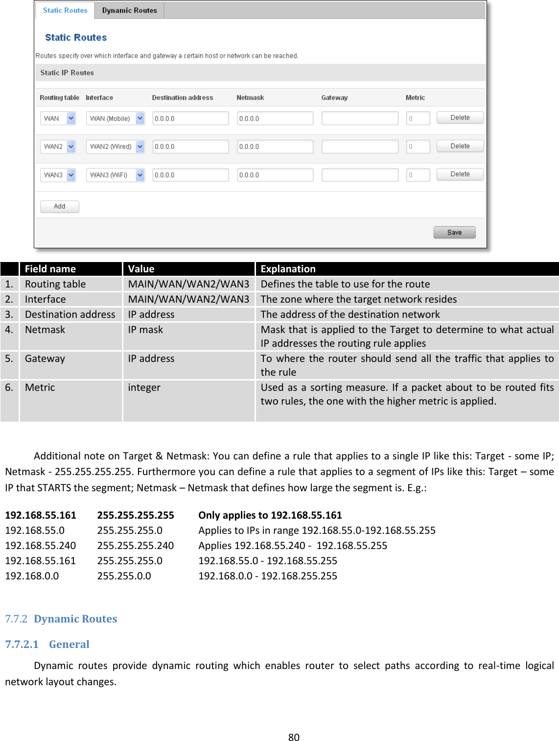
![29 Redundancy Protocol) cluster will act as a master, range [1 - 255] 4. Router** Master Connection mode – Master **-Exclusive to other Modes with Slave. 6.3.1.10 Topology Network scanner allows you to quickly retrieve information about network devices. When router is configured to use Mobile as WAN and Connection type is selected „PPP“, then possible to scan only the LAN side. 6.3.1.11 Access Display information about local and remote active connections status. Field Name Sample Value Explanation 1. Type SSH; HTTP; HTTPS Type of connection protocol 2. Status Disabled/Enabled Connection status 3. Port 22; 80; 443 Connection port used 4. Active 0(0.00B);1(9.26 KB); Count of active connections and amount of data transmitted in KB](https://usermanual.wiki/UAB-Teltonika/RUT955A.User-Manual-1/User-Guide-4043741-Page-29.png)
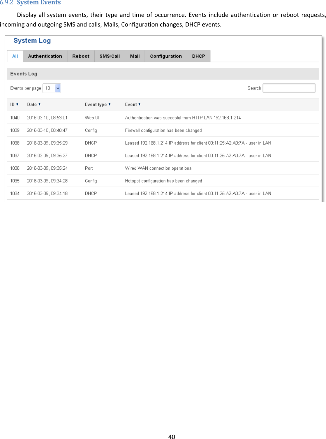

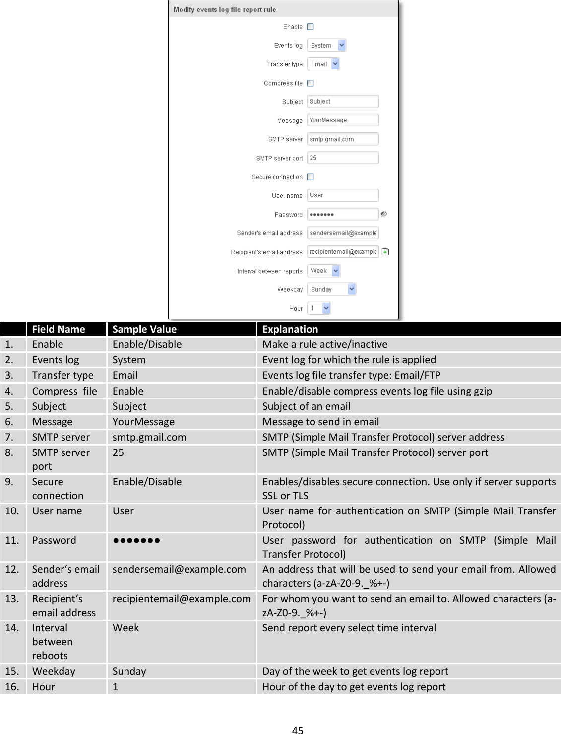
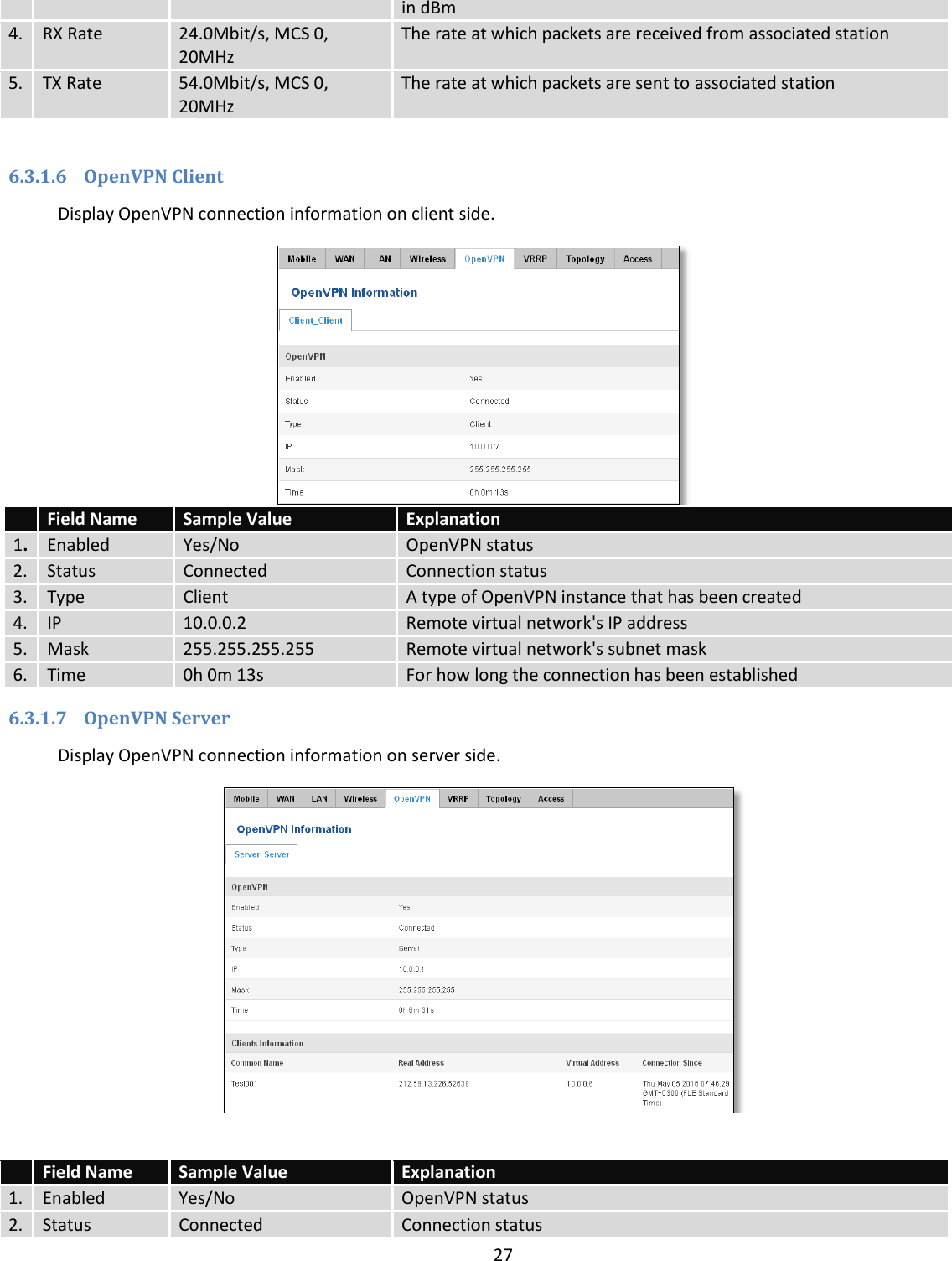
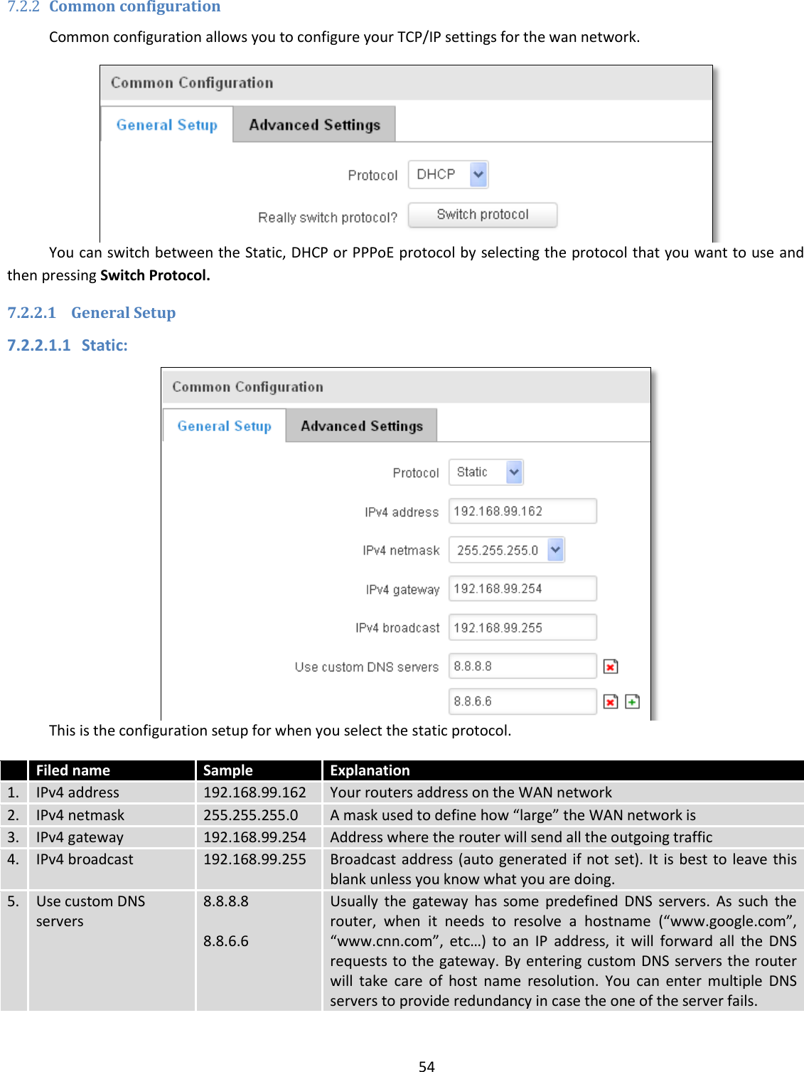
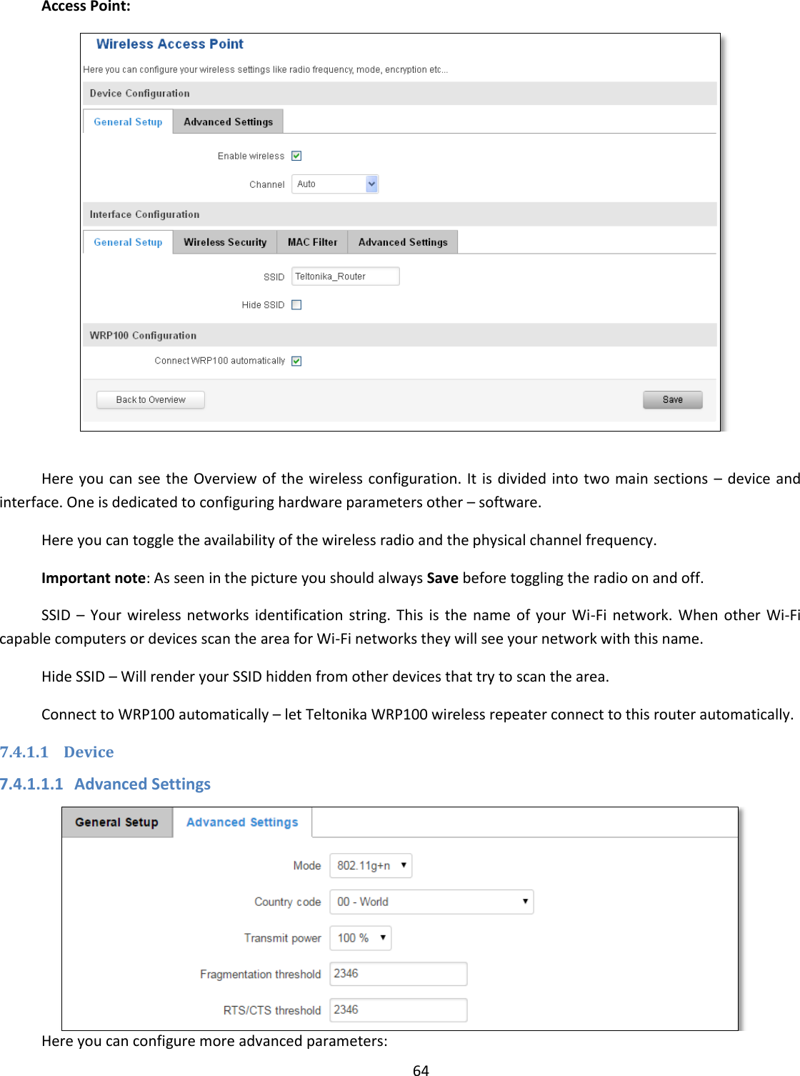
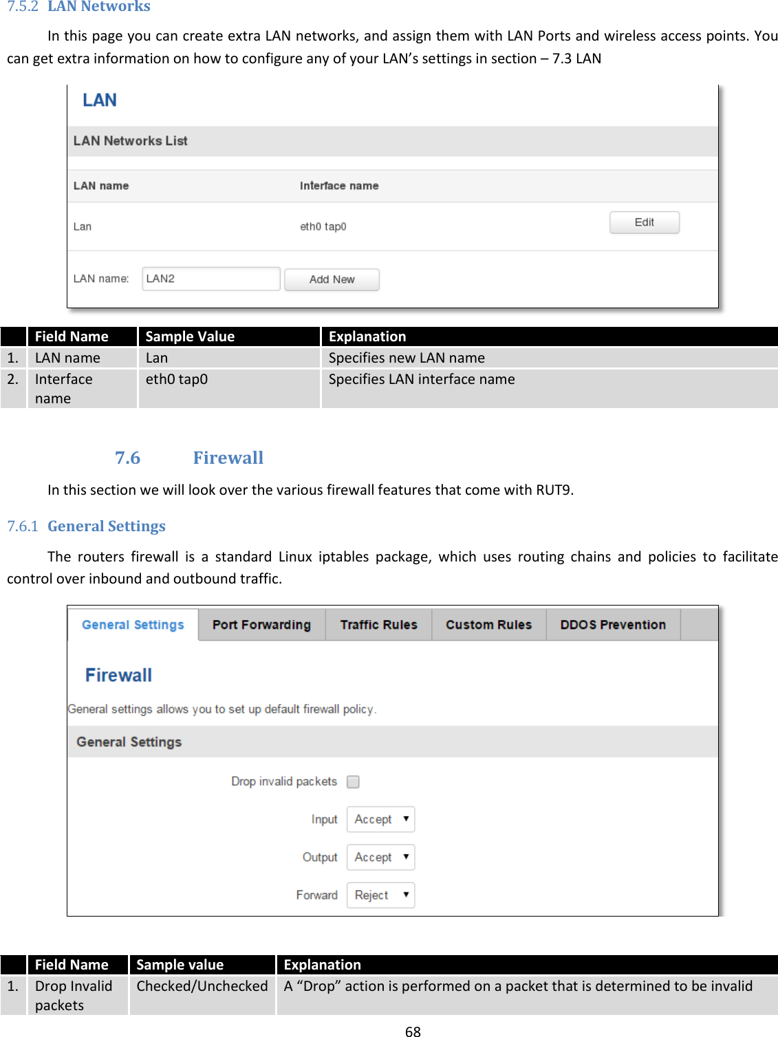
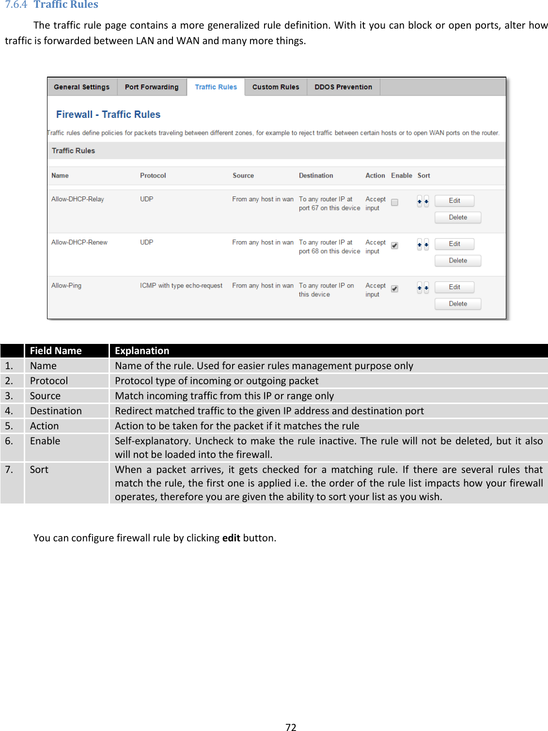
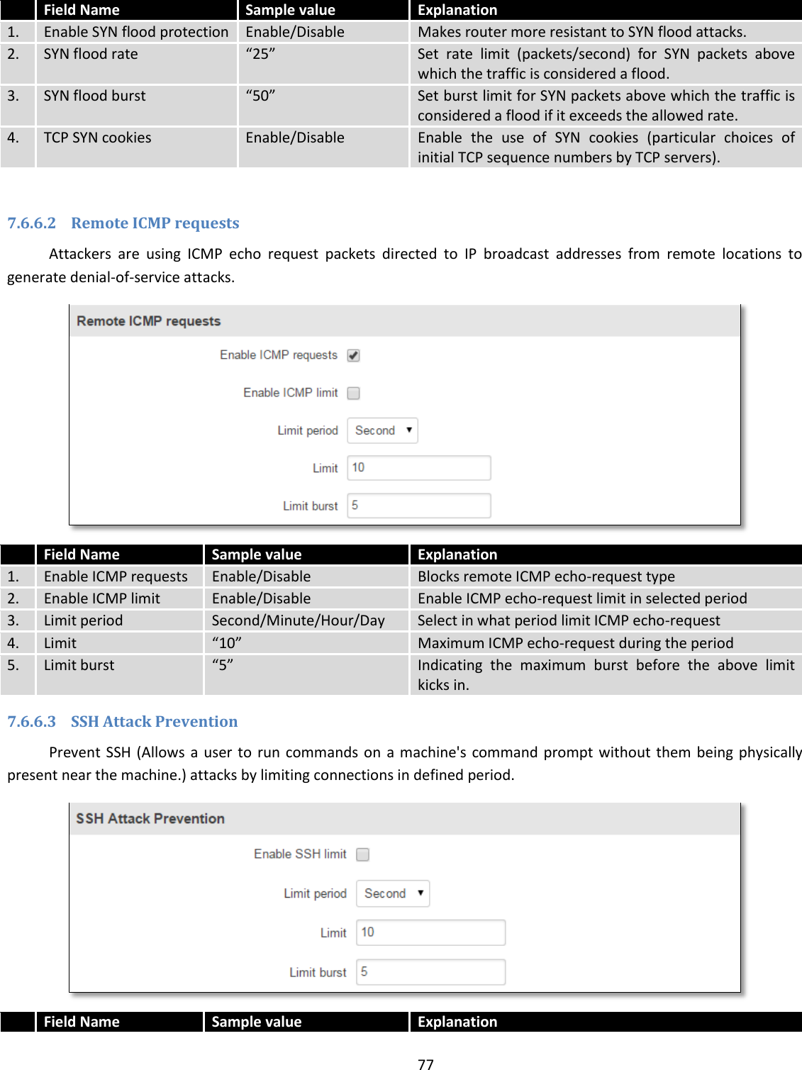
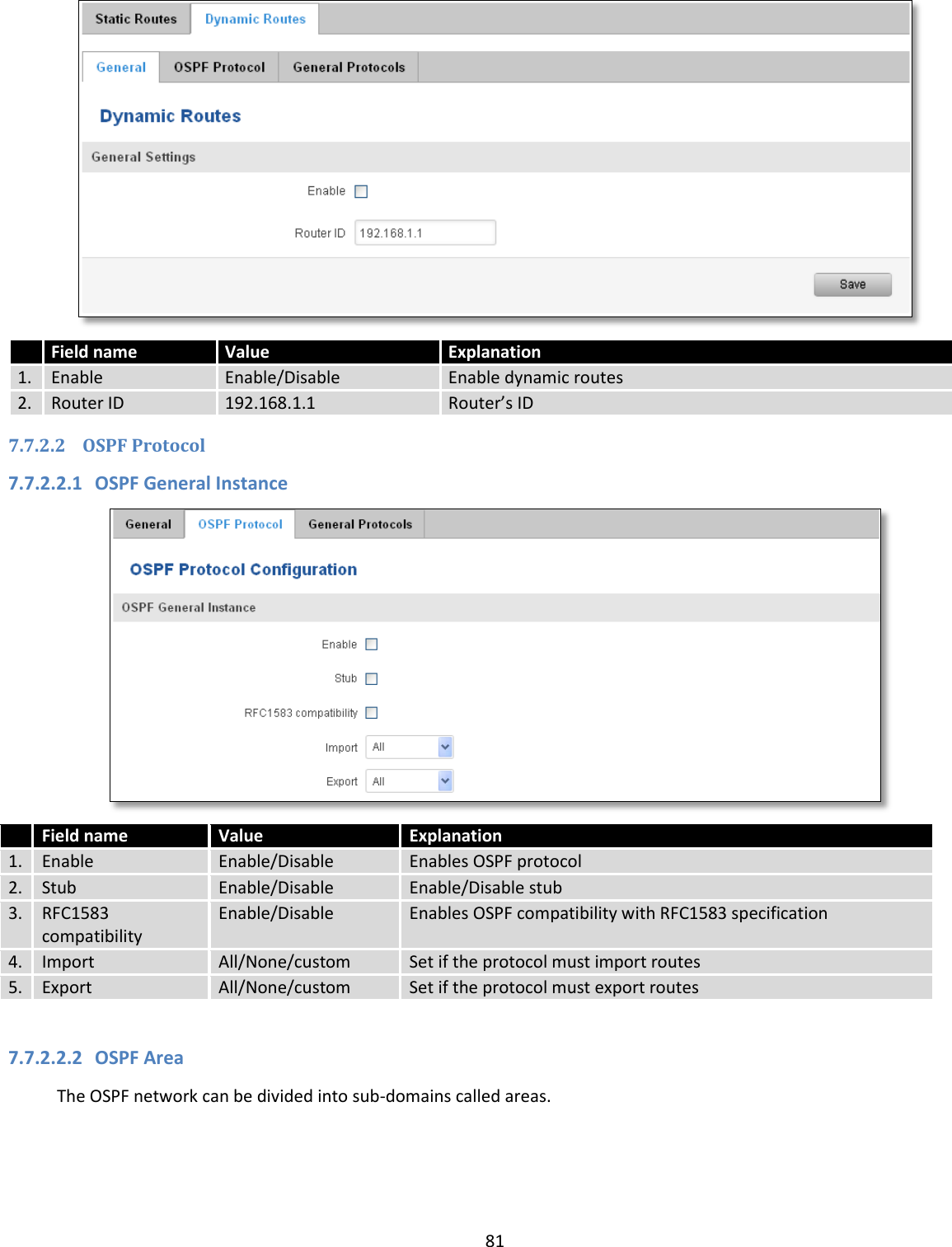
![48 7.1.1.2 Mobile Data On Demand Field name Possible values Explanation 1. Enable Enable/Disable Mobile Data On Demand function enables you to keep mobile data connection on only when it's in use 2. No data timeout(sec) 1-99999999 A mobile data connection will be terminated if no data is transferred during the timeout period 7.1.1.3 Force LTE network Field name Possible values Explanation 1. Enable Enable/Disable Enable/disable try to connect to LTE network every x seconds (used only if service mode is set to 4G (LTE) preferred) 2. Reregister Enable/Disable If this enabled, modem will be reregister before try to connect to LTE network 3. Interval (sec) 180 - 3600 Time in seconds between tries to connect to LTE network. Range [180-3600]](https://usermanual.wiki/UAB-Teltonika/RUT955A.User-Manual-1/User-Guide-4043741-Page-48.png)

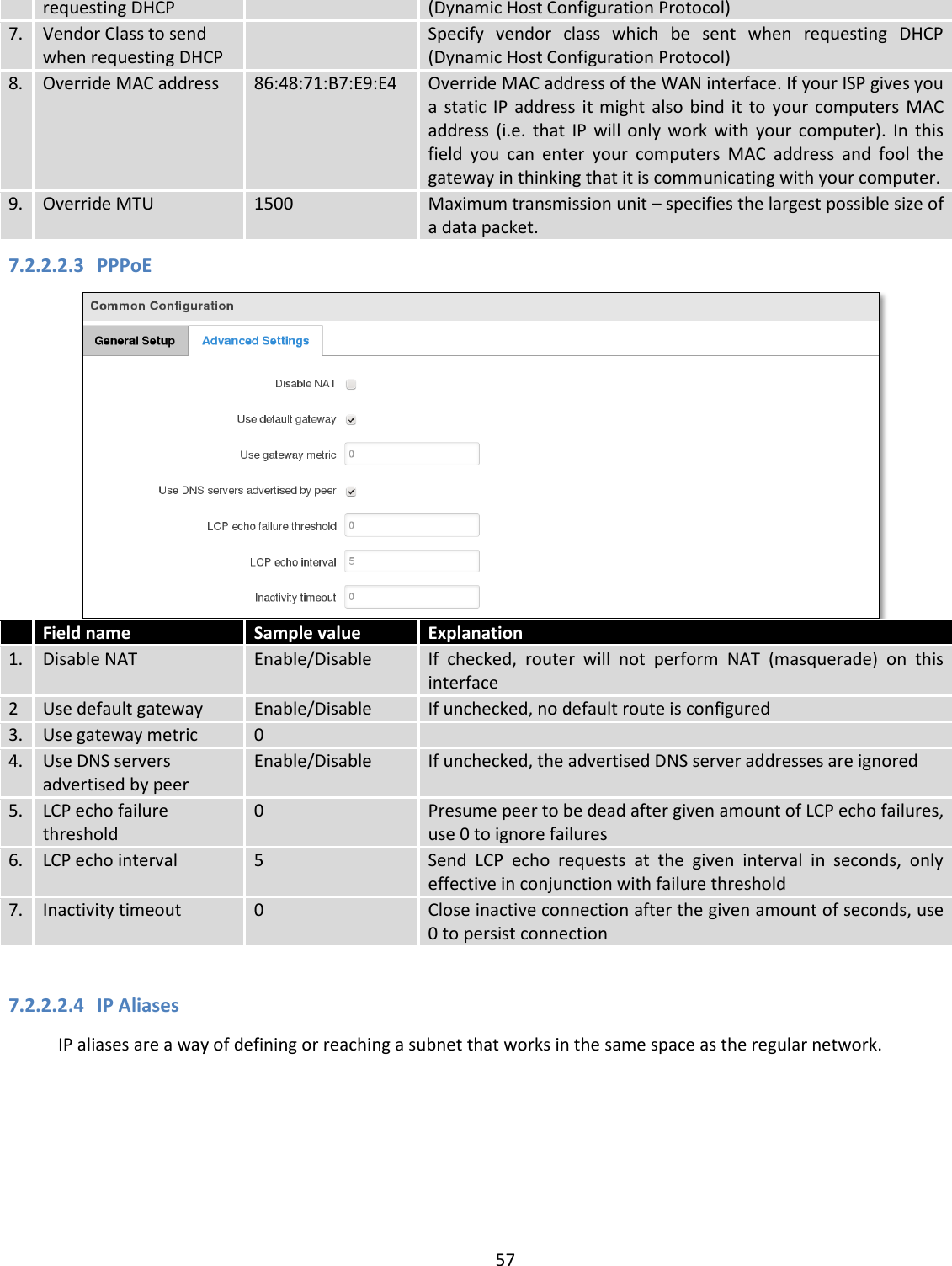
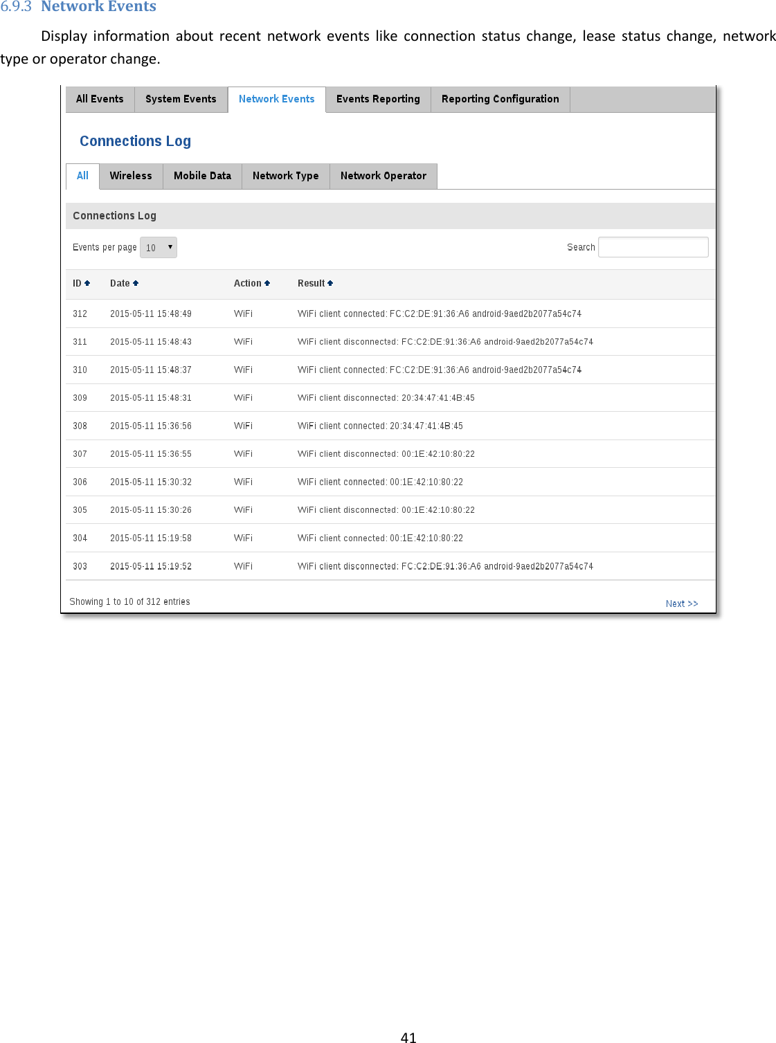
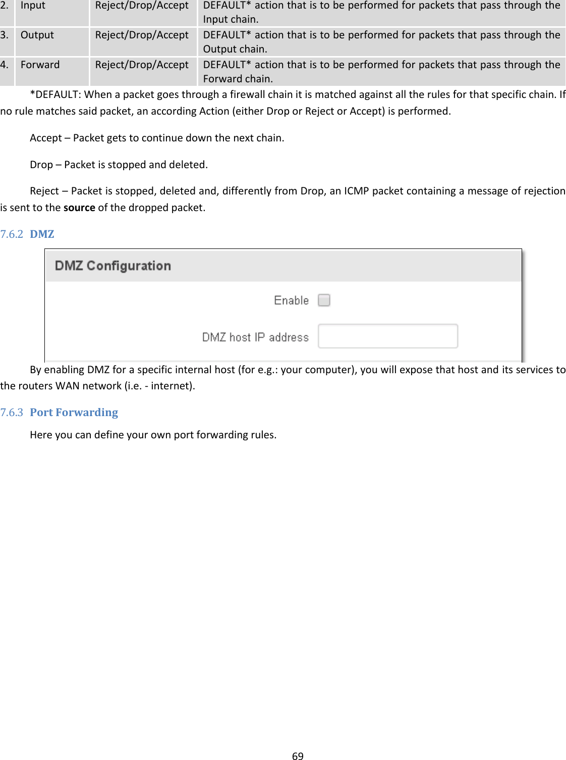
. If the Start value is set to 100 then the DHCP server will only be able to lease out addresses starting from 192.168.2.100 3. Limit 155 How many addresses the DHCP server gets to lease out. Continuing on the above example: if the start address is 192.168.2.100 then the end address will be 192.168.2.254 (100 + 155 – 1 = 254). 4. Lease time 12 How long can a leased IP be considered valid. An IP address after the specified amount of time will expire and the device that leased it out will have to request for a new one. Select Hour or Minute (minimum 2min).](https://usermanual.wiki/UAB-Teltonika/RUT955A.User-Manual-1/User-Guide-4043741-Page-61.png)
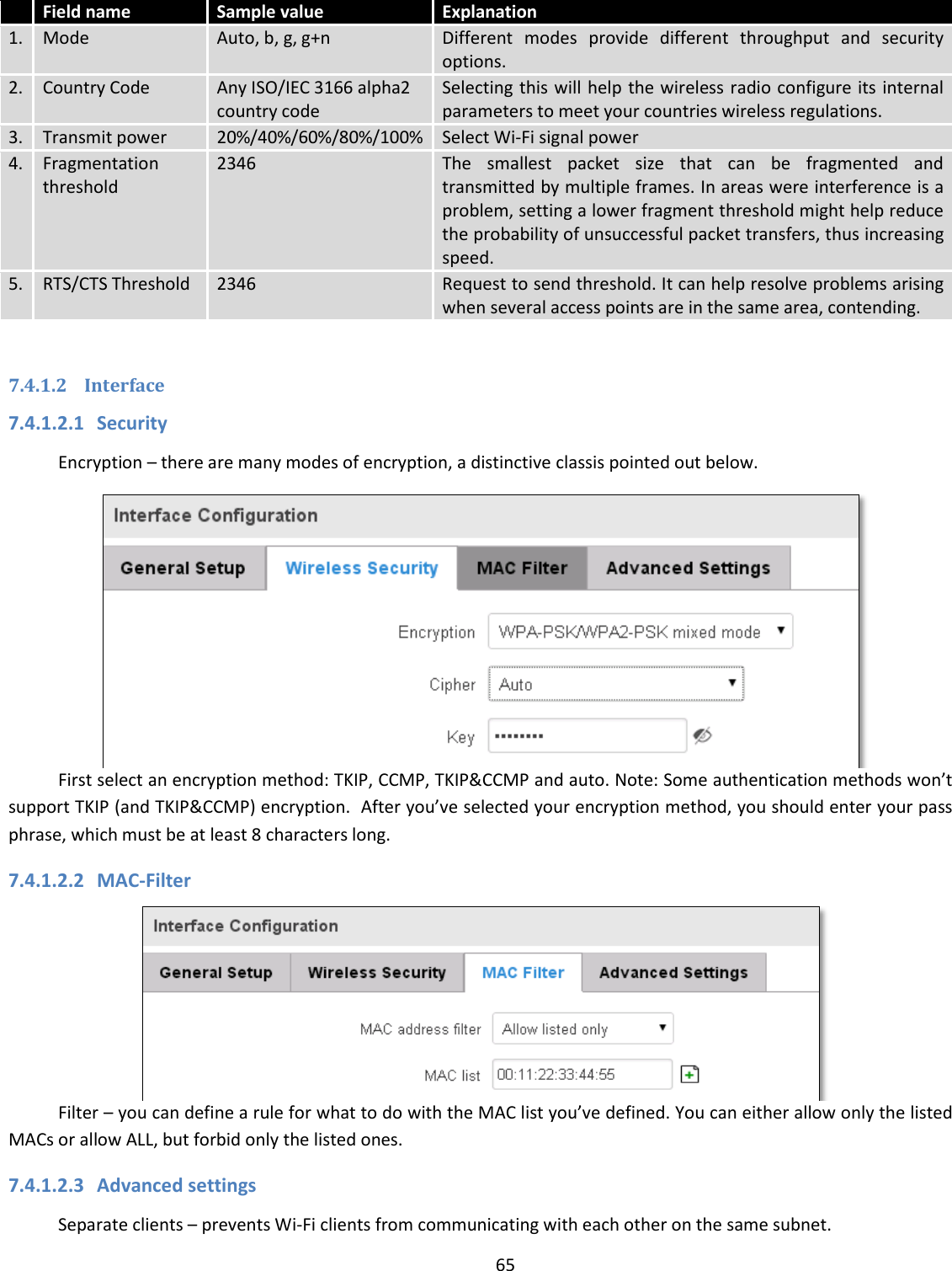
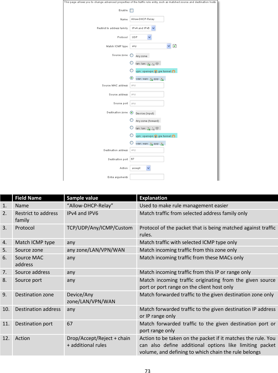

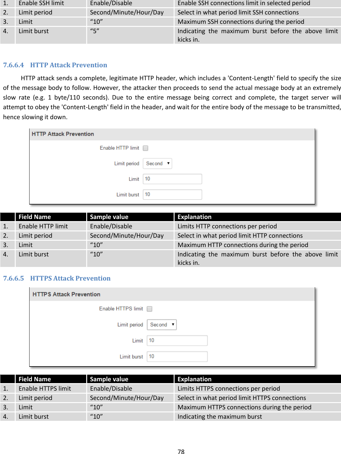
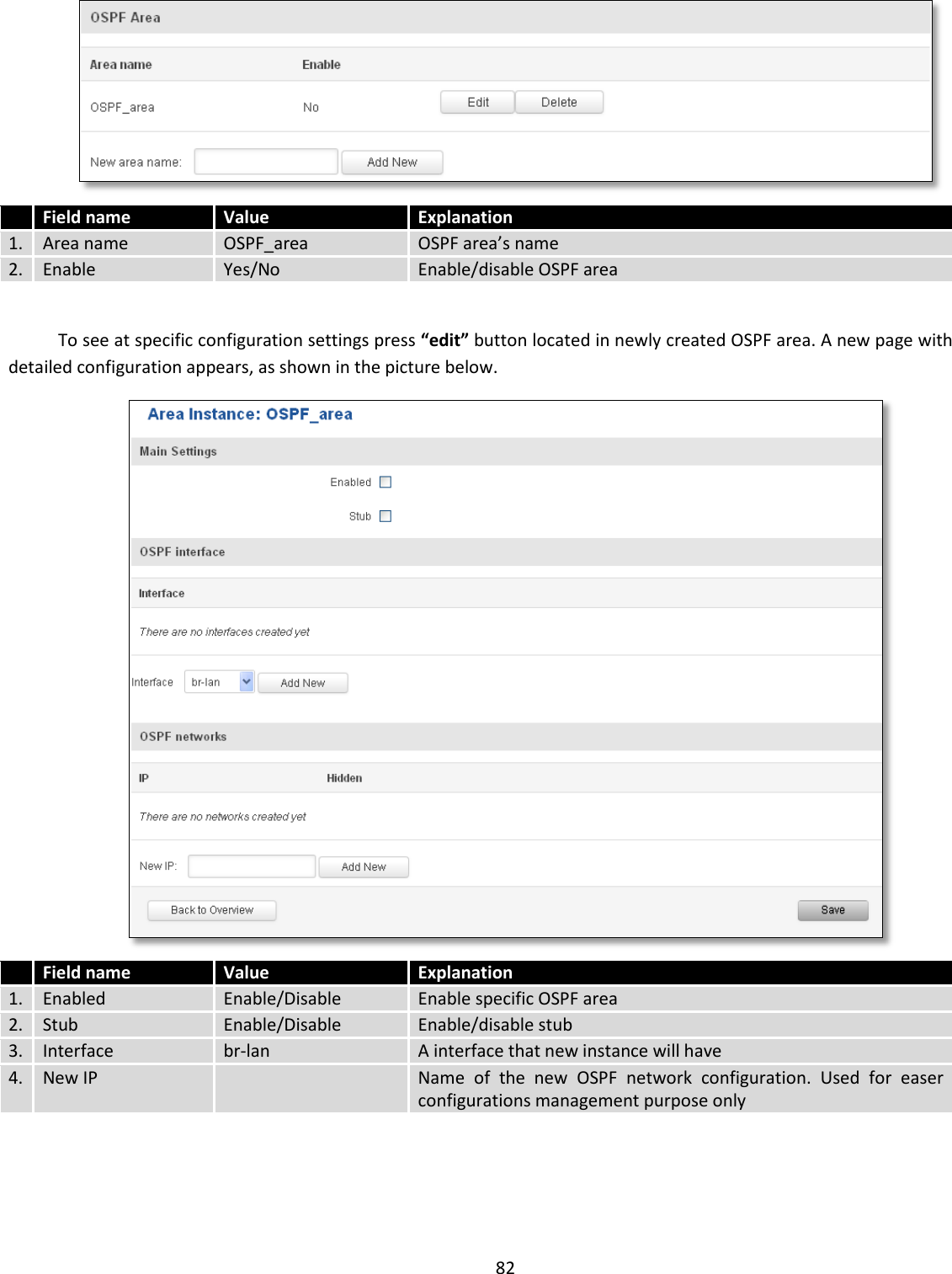
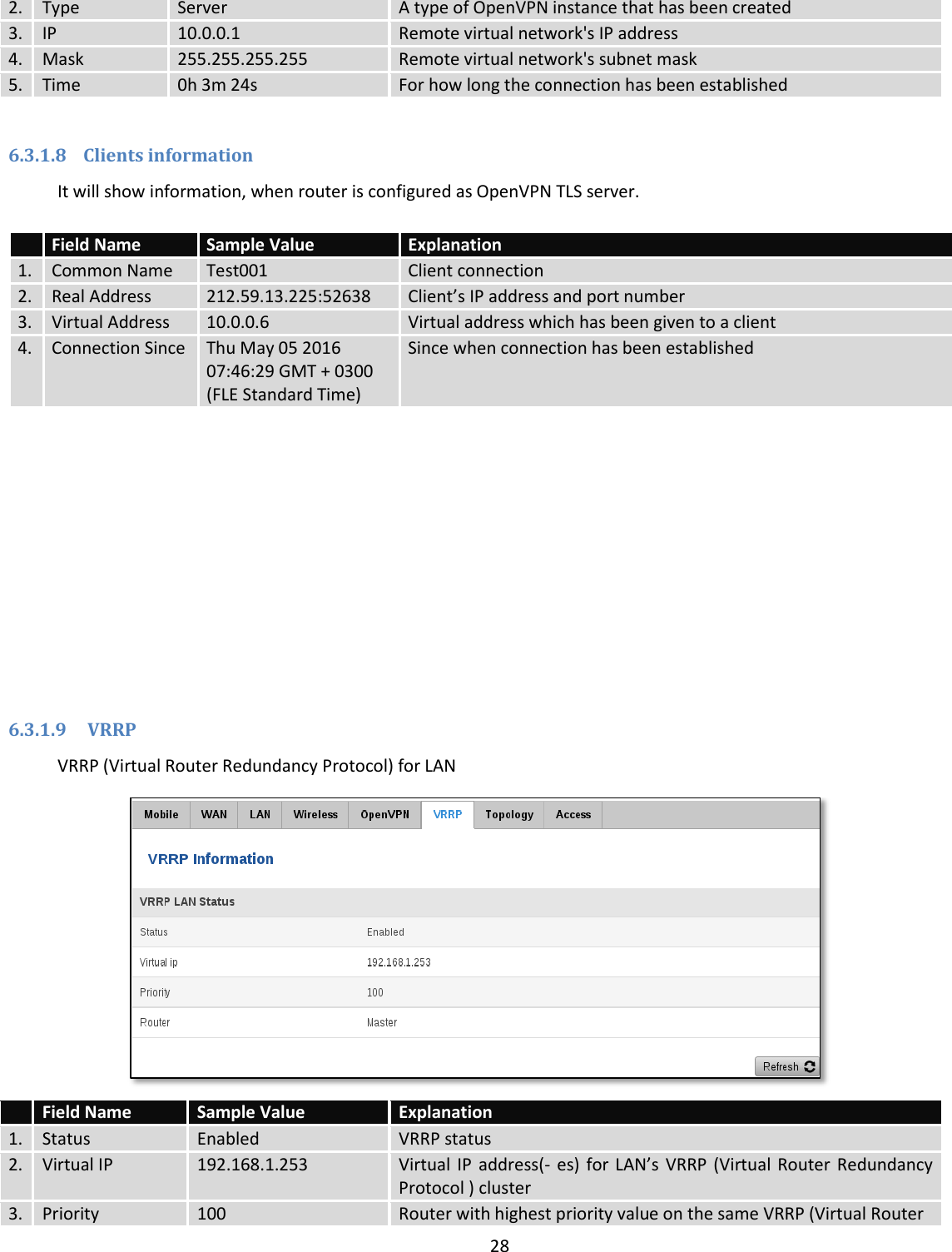
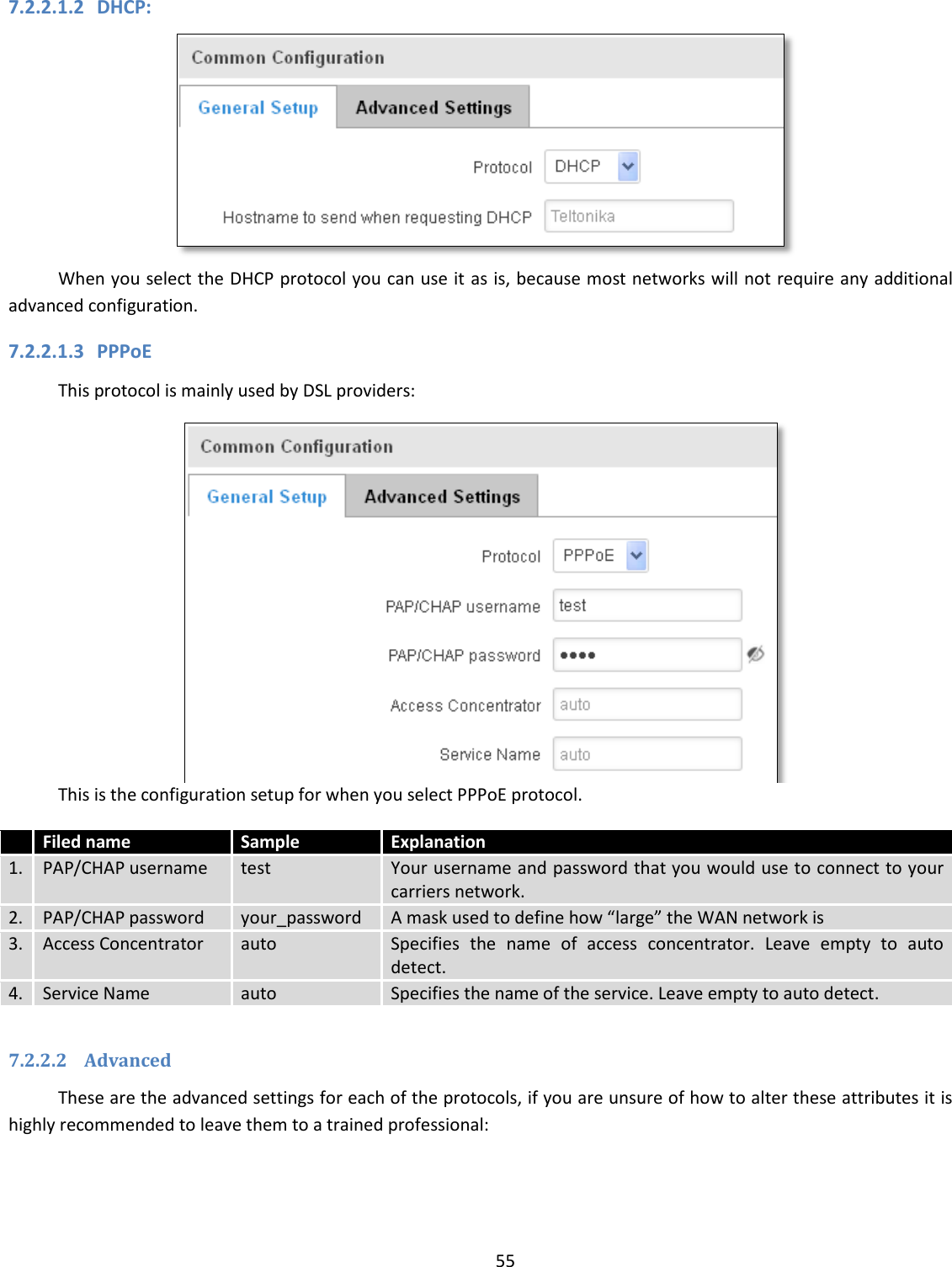
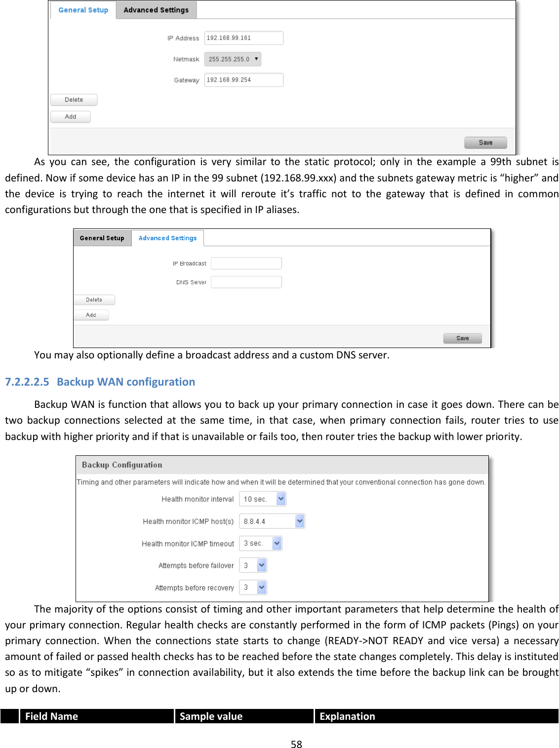
![86 Application Can obtain parameters Can set parameters 1. MQTT publisher o 2. MODBUS daemon 3. SSH 4. RMS 5. SMS 6. SNMP o 7. JSON-RPC By summarizing, RUT9XX provides several solutions for router management. Each user can choose what solution to use. If required functionality is not found in particular service, the user can combine several applications, for example, use MQTT publisher along with SNMP. Finally, if user has special needs, he can write shell script and execute it via SSH or use json-rpc. 9 Services 9.1 VRRP 9.1.1 VRRP LAN Configuration Settings Field name Sample Explanation 1. Enable Enable/Disable Enable VRRP (Virtual Router Redundancy Protocol) for LAN 2. IP address 192.168.1.253 Virtual IP address for LAN's VRRP (Virtual Router Redundancy Protocol) cluster 3. Virtual ID 1 Routers with same IDs will be grouped in the same VRRP (Virtual Router Redundancy Protocol) cluster, range [1-255] 4. Priority 100 Router with highest priority value on the same VRRP (Virtual Router Redundancy Protocol) cluster will act as a master, range [1-255]](https://usermanual.wiki/UAB-Teltonika/RUT955A.User-Manual-1/User-Guide-4043741-Page-86.png)
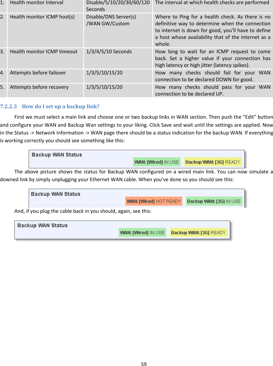
![87 9.1.2 Check Internet connection Field name Sample Explanation 1. Enable Enable/Disable Enable WAN's connection monitoring 2. Ping IP address 8.8.4.4 A host to send ICMP (Internet Control Message Protocol) packets to 3. Ping interval 10 Time interval in seconds between two Pings 4. Ping timeout (sec) 1 Response timeout value, interval [1 - 9999] 5. Ping packet size 50 ICMP (Internet Control Message Protocol) packet's size, interval [0 - 1000] 6. Ping retry count 100 Failed Ping attempt’s count before determining that connection is lost, interval [1 – 9999] 9.2 TR-069 TR-069 is a standard developed for automatic configuration and management of remote devices by Auto Configuration Servers (ACS). 9.2.1 TR-069 Parameters Configuration Field name Sample Explanation 1. Enable Enable/Disable Enable TR-069 client 2. Enable Periodic Transmission Enable / Disable Enable periodic transmissions of data to server 3. User name admin User name for authentication on TR-069 server 4. Password ******* Password for authentication on TR-069 server 5. URL http://192.168.1.110:8080 TR-069 server URL address](https://usermanual.wiki/UAB-Teltonika/RUT955A.User-Manual-1/User-Guide-4043741-Page-87.png)