UAB Teltonika RUT955A GPS Tracker User Manual 2
UAB Teltonika GPS Tracker 2
UserManual.wiki
>
UAB Teltonika
>
RUT955A User Manual
>
User Manual 2
Contents
1.
User Manual 1
2.
User Manual 2
3.
User Manual 3
4.
User Manual - Regulatory Guide
User Manual 2
Navigation menu
Upload a User Manual
Namespaces
Wiki Guide
HTML
PDF
Info
Views
User Manual
Discussion / Help
Navigation
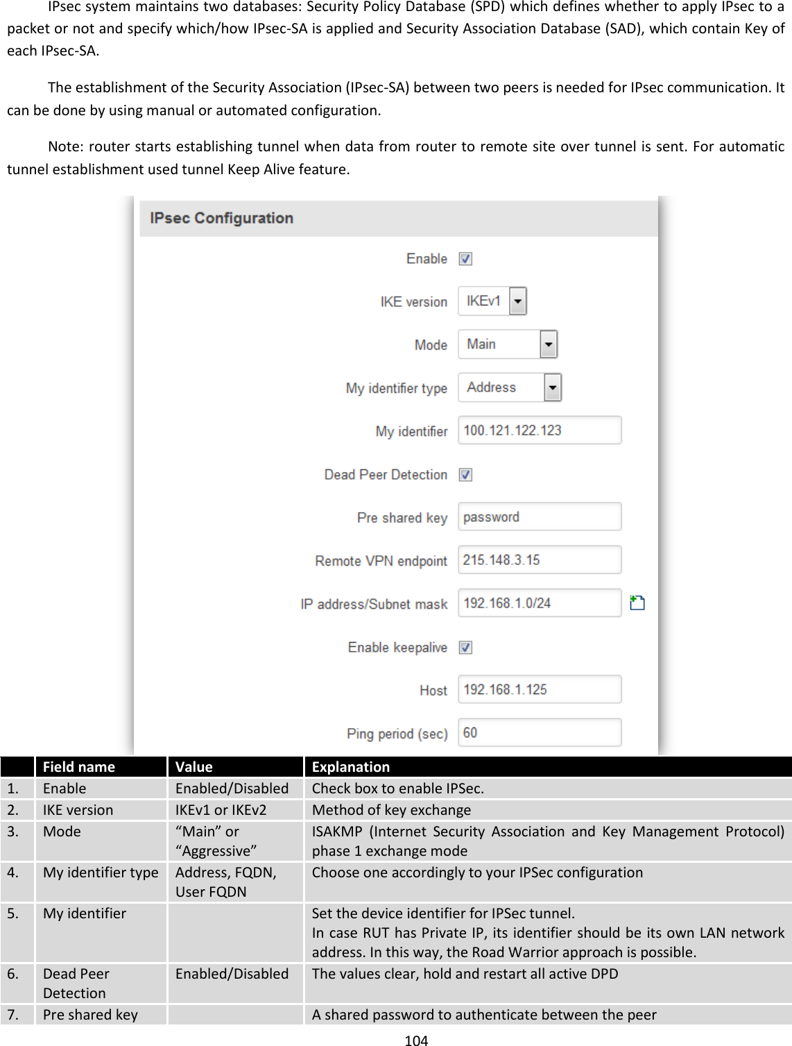
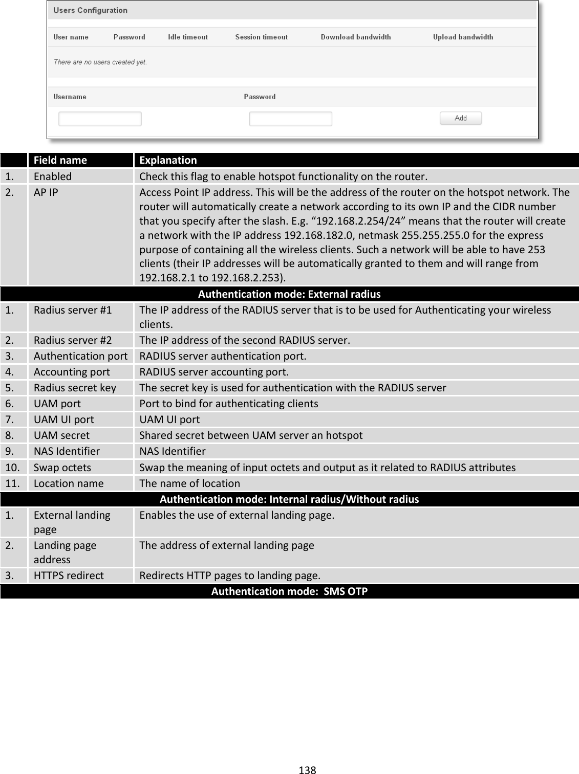
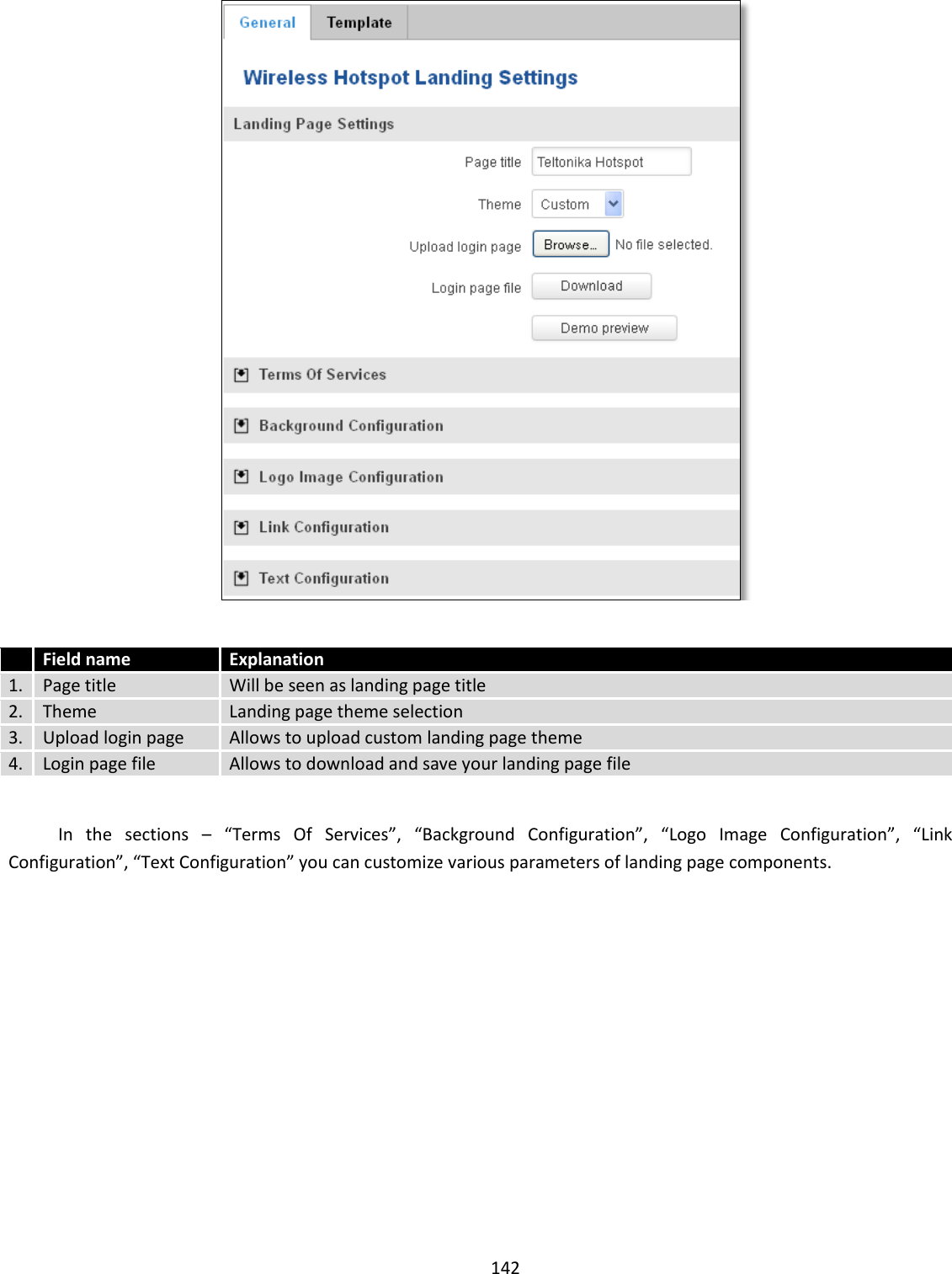
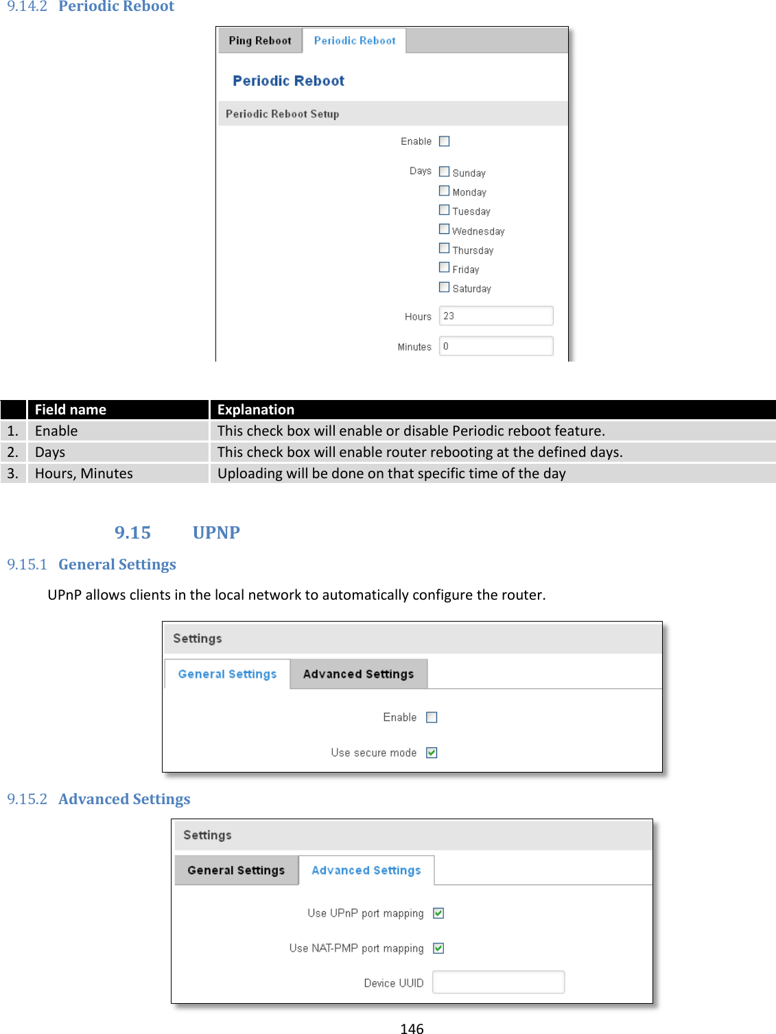
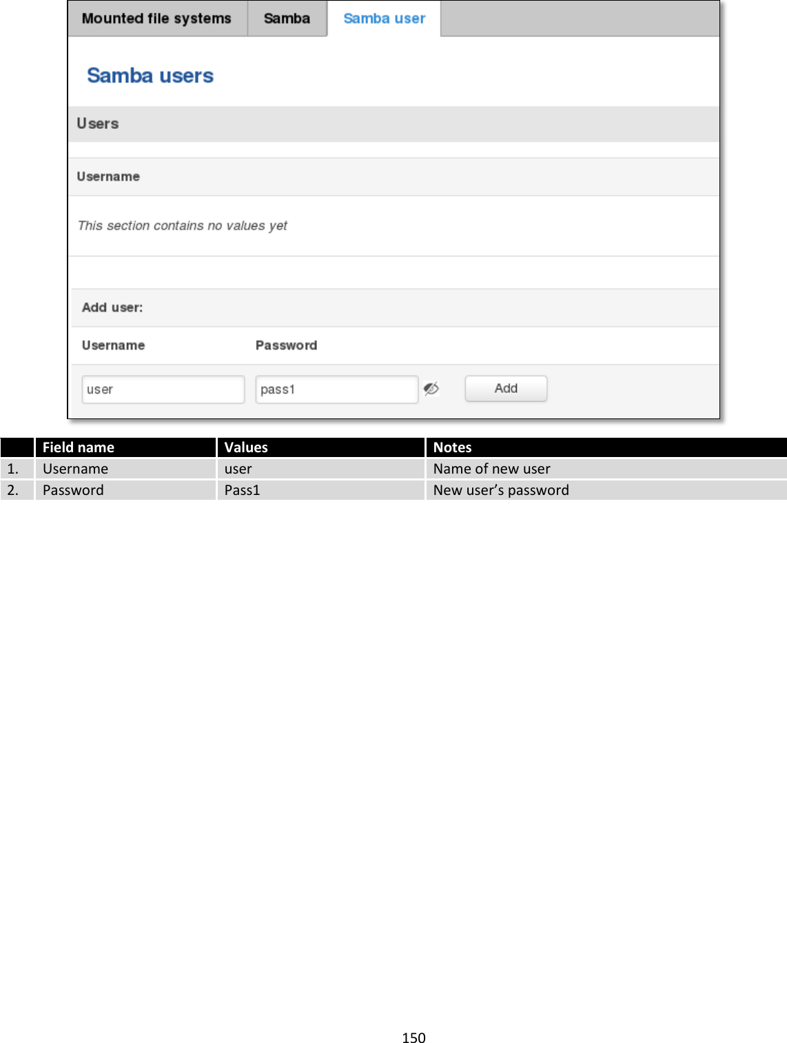
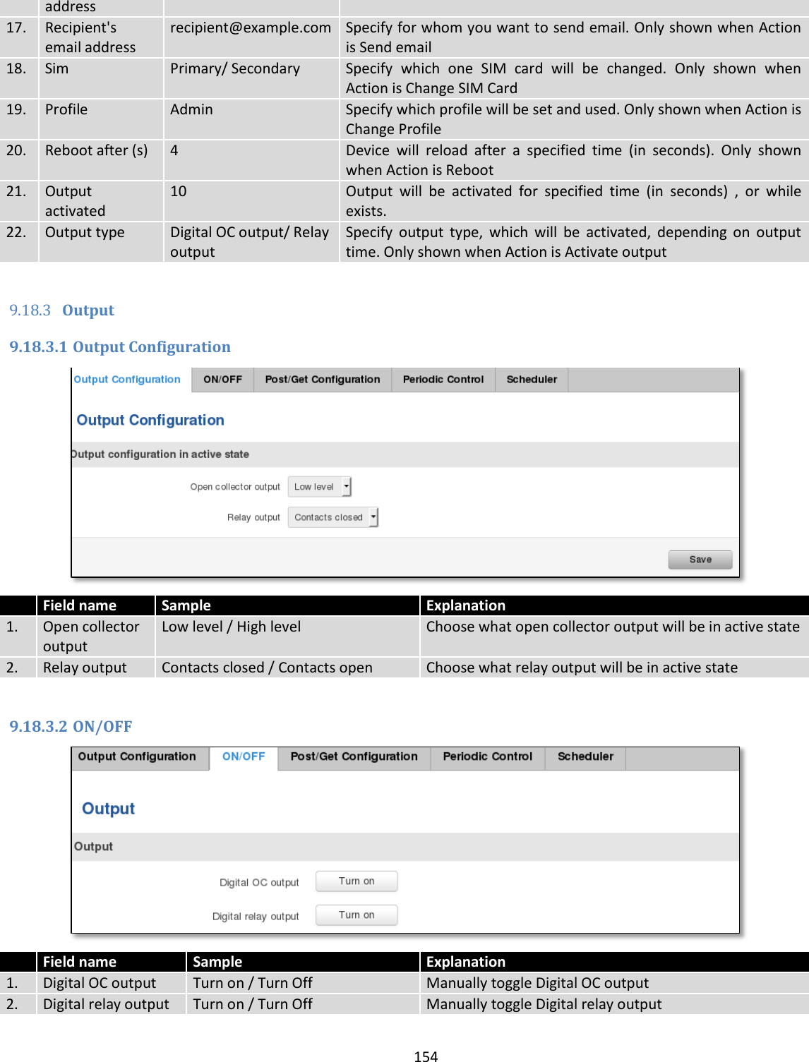
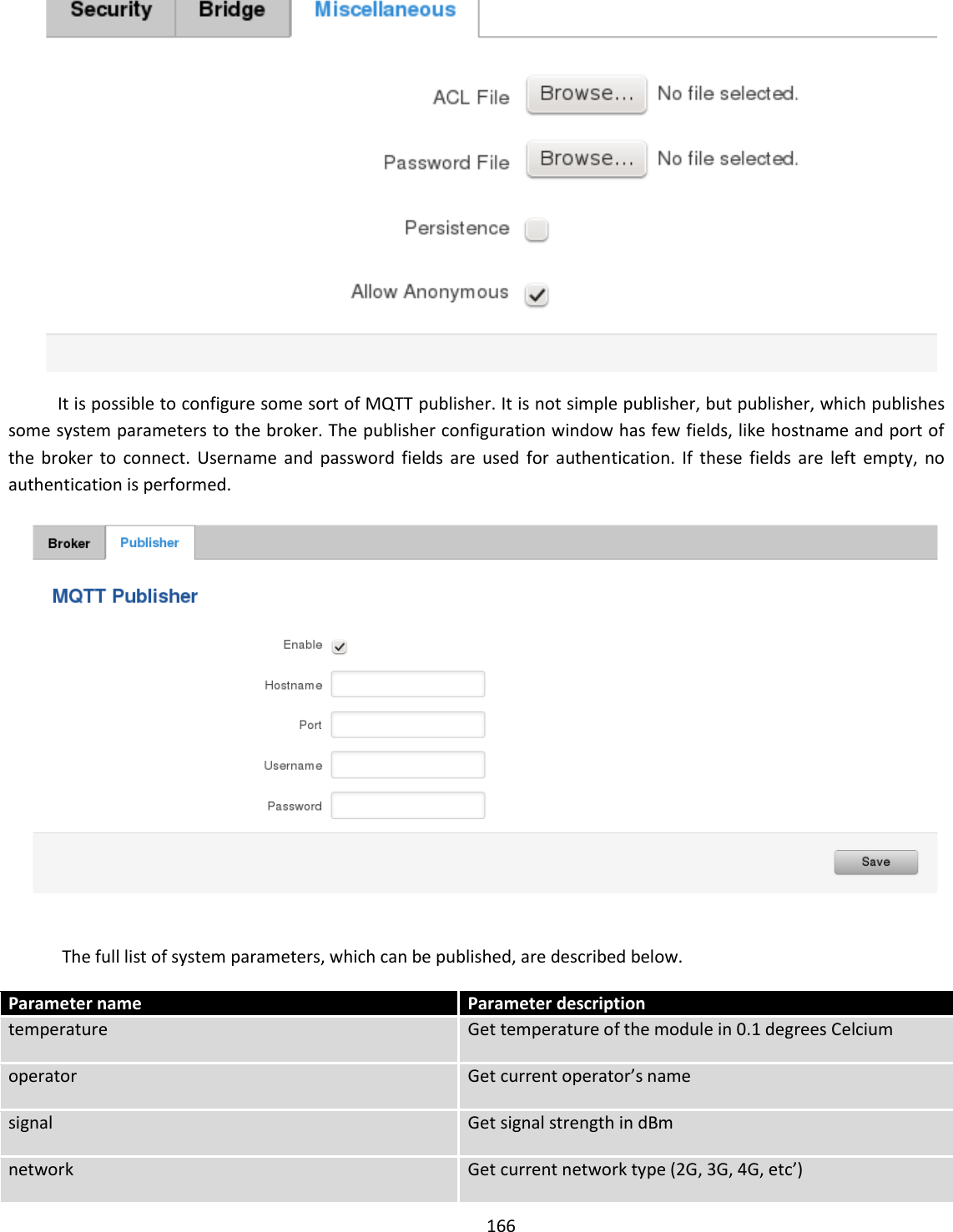
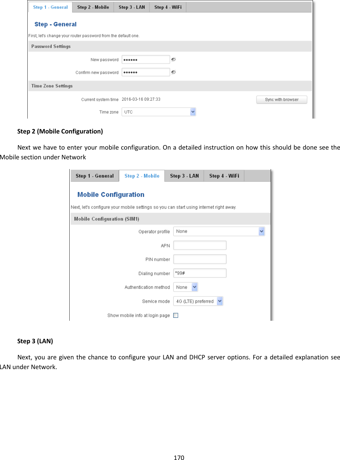
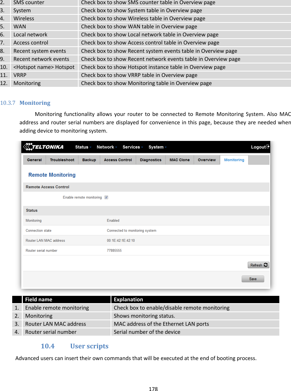
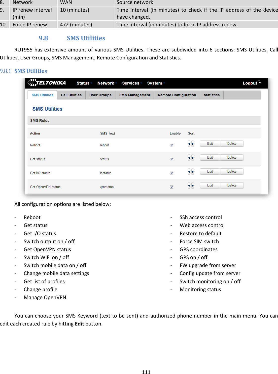
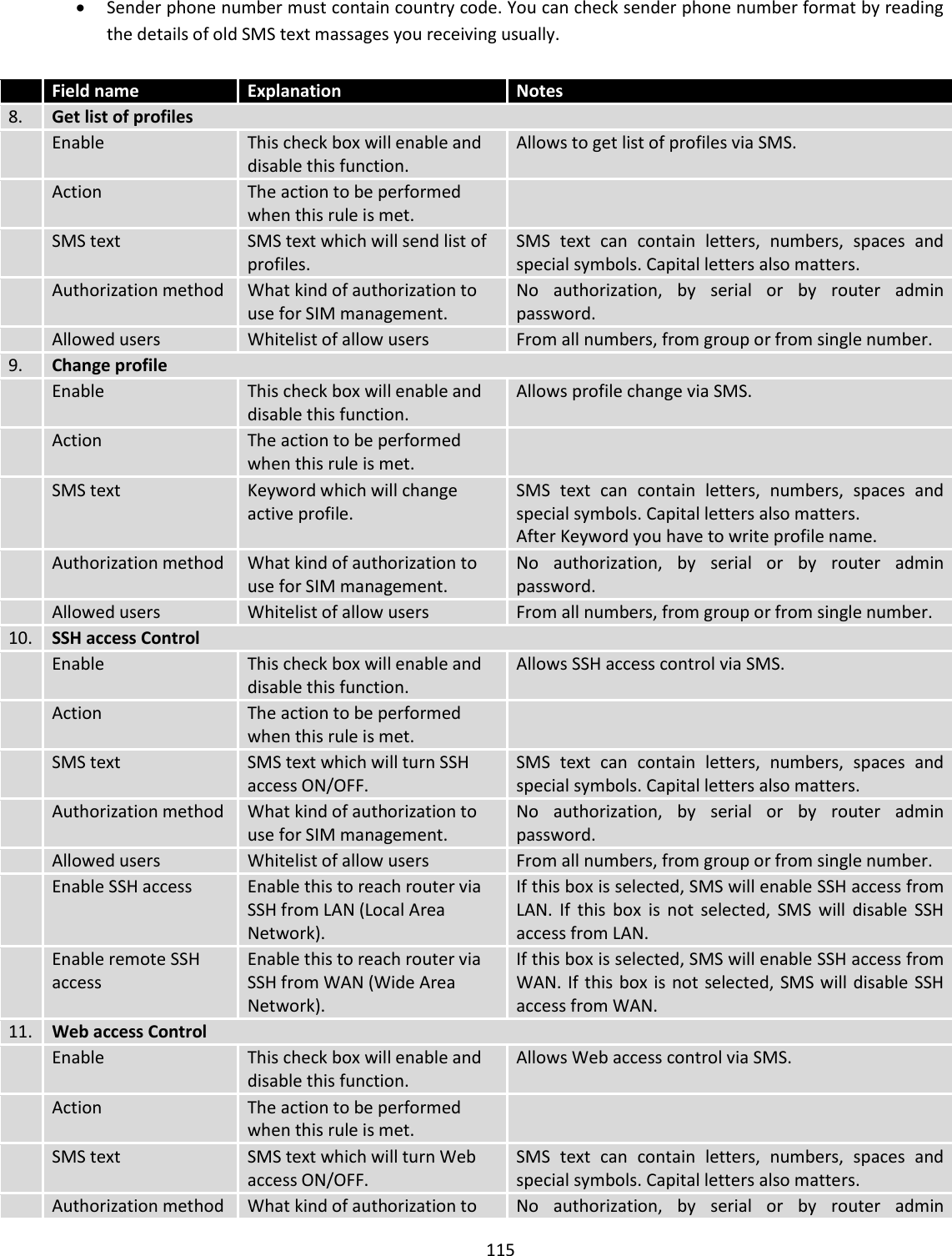
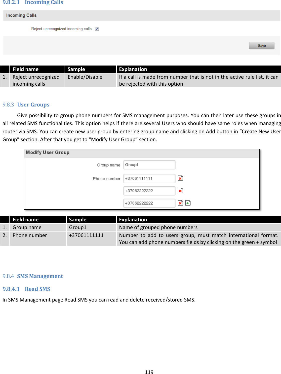
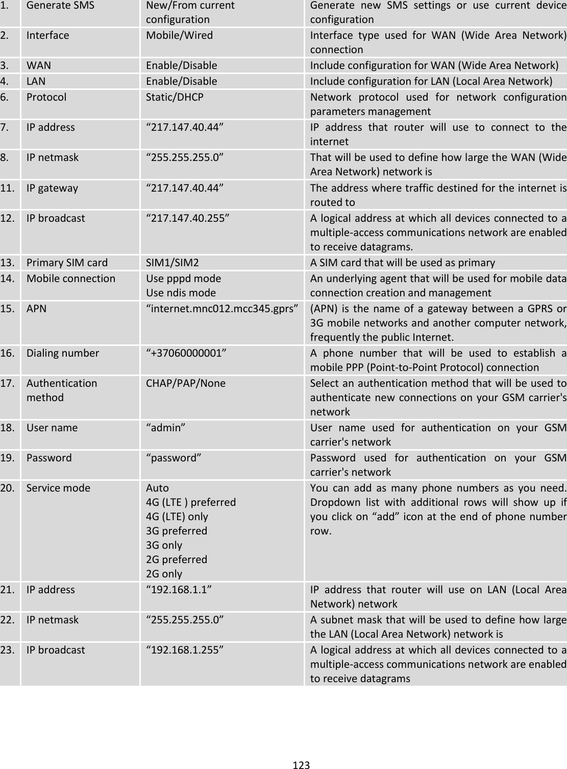
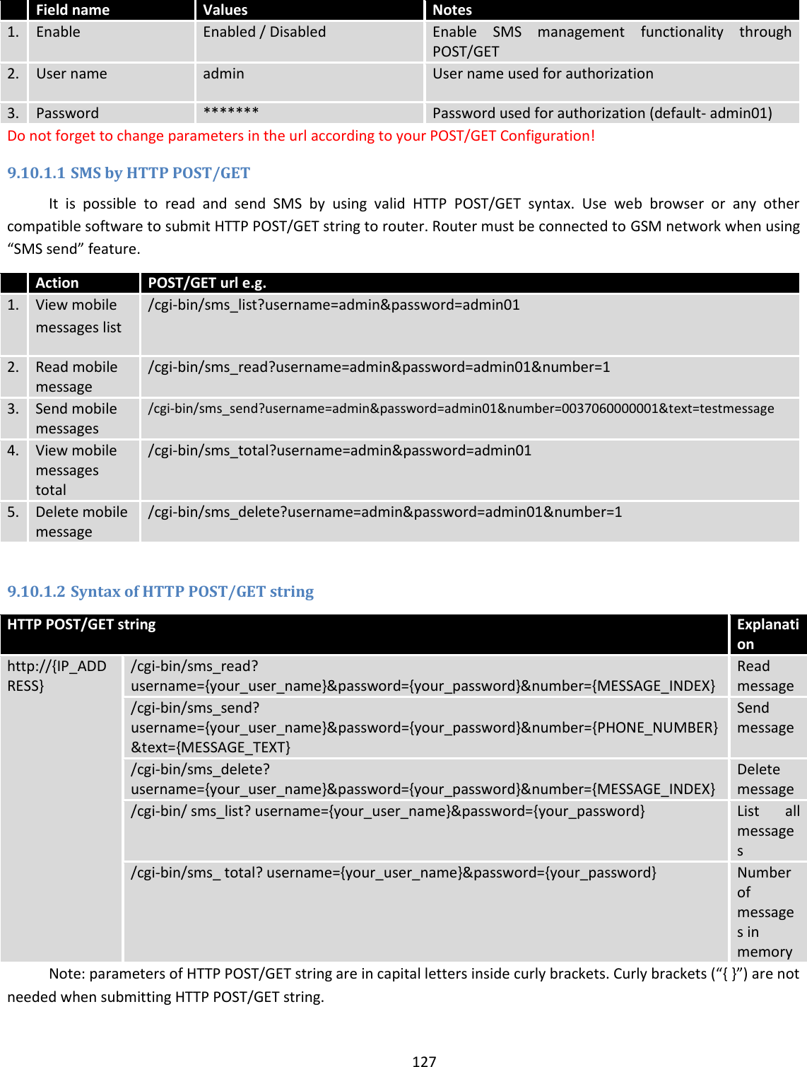
![105 8. Remote VPN endpoint Domain name or IP address. Leave empty or any 9. IP address/Subnet mask Remote network secure group IP address and mask used to determine to what subnet an IP address belongs to. Range [0-32]. IP should differ from device LAN IP 10. Enable keep alive Enabled/Disabled Enable tunnel keep alive function 11. Host A host address to which ICMP (Internet Control Message Protocol) echo requests will be send 12. Ping period (sec) Send ICMP echo request every x seconds. Range [0-999999] Phase 1 and Phase 2 must be configured accordingly to the IPSec server configuration, thus algorithms, authentication and lifetimes of each phase must be identical. Field name Value Explanation 1. Encryption algorithm DES, 3DES, AES 128, AES 192, AES256 The encryption algorithm must match with another incoming connection to establish IPSec 2. Authentication MD5, SHA1, SHA256, SHA384, SHA512 The authentication algorithm must match with another incoming connection to establish IPSec 3. Hash algorthm MD5, SHA1, SHA256, SHA384, SHA512 The hash algorithm must match with another incoming connection to establish IPSec 4. DH group MODP768, MODP1024, MODP1536, MODP2048, MODP3072, MODP4096 The DH (Diffie-Helman) group must with another incoming connection to establish IPSec 4. PFS group MODP768, MODP1024, MODP1536, MODP2048, MODP3072, MODP4096, No PFS The PFS (Perfect Forward Secrecy) group must match with another incoming connection to establish IPSec 5. Lifetime Hours, Minutes, Seconds The time duration for phase](https://usermanual.wiki/UAB-Teltonika/RUT955A.User-Manual-2/User-Guide-4043742-Page-15.png)

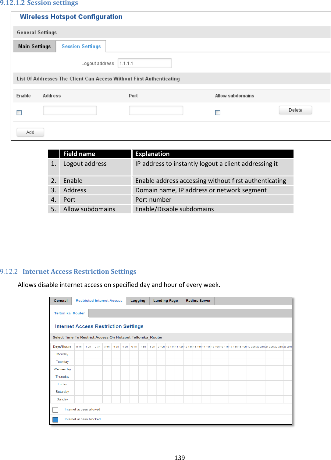
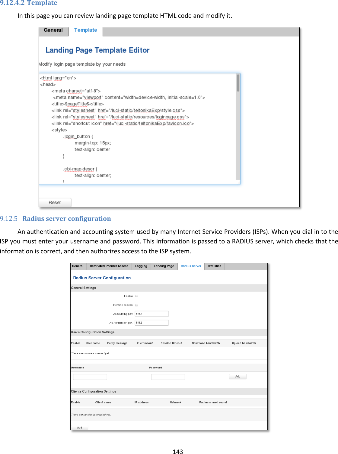
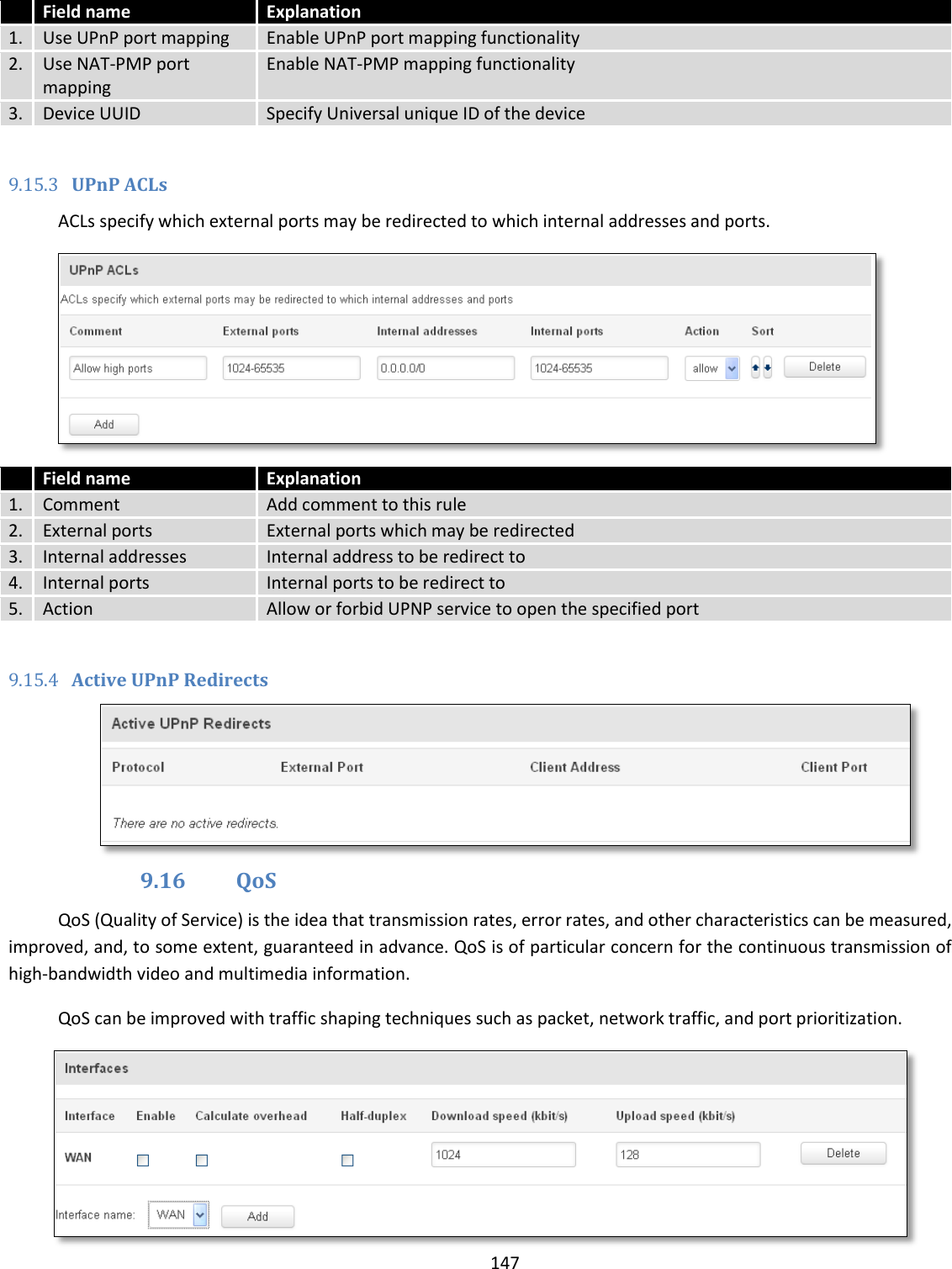
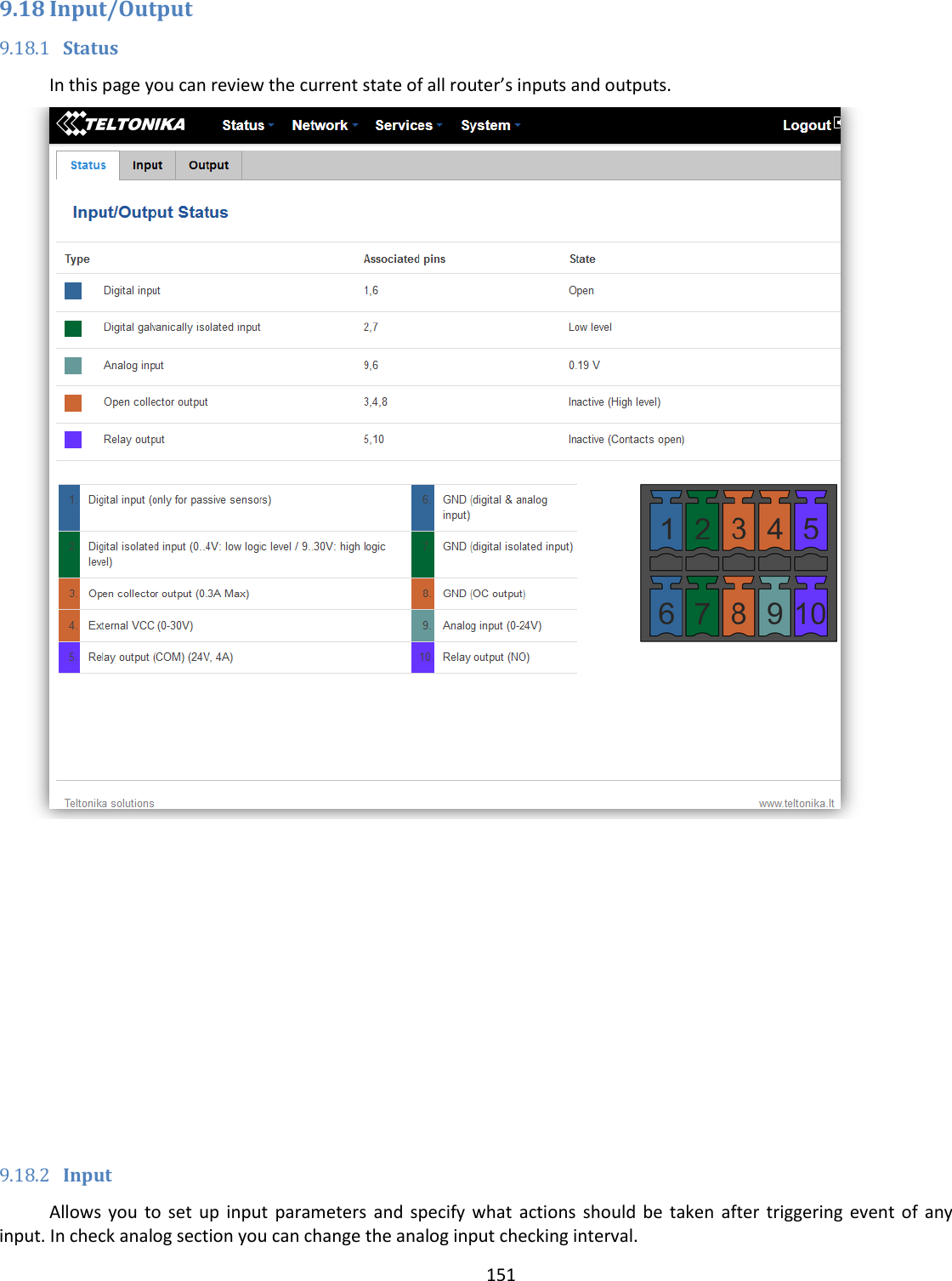
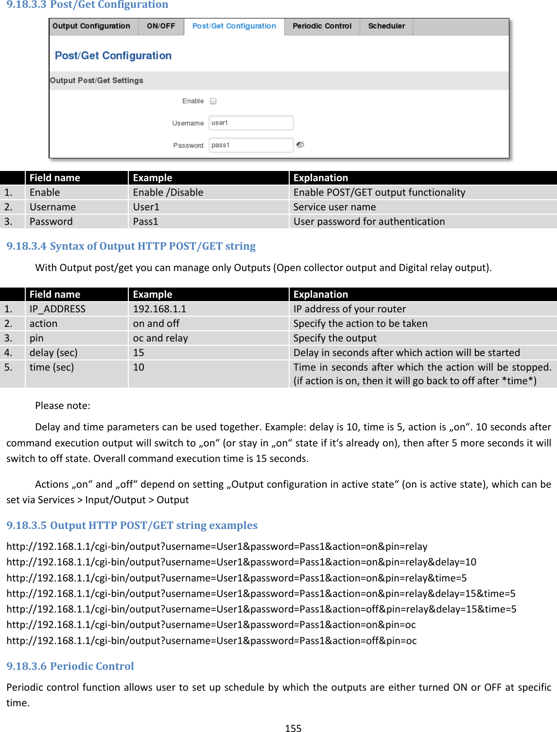
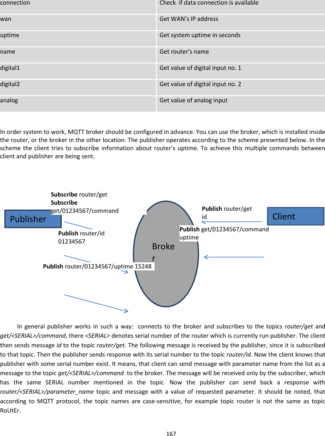
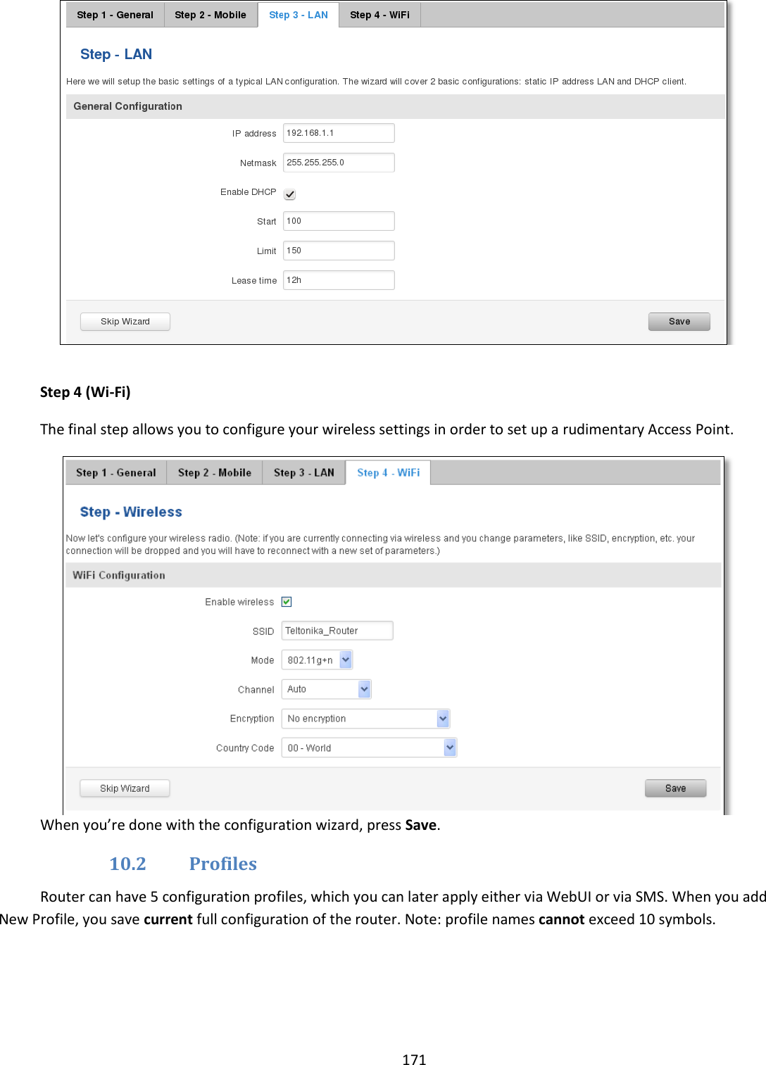
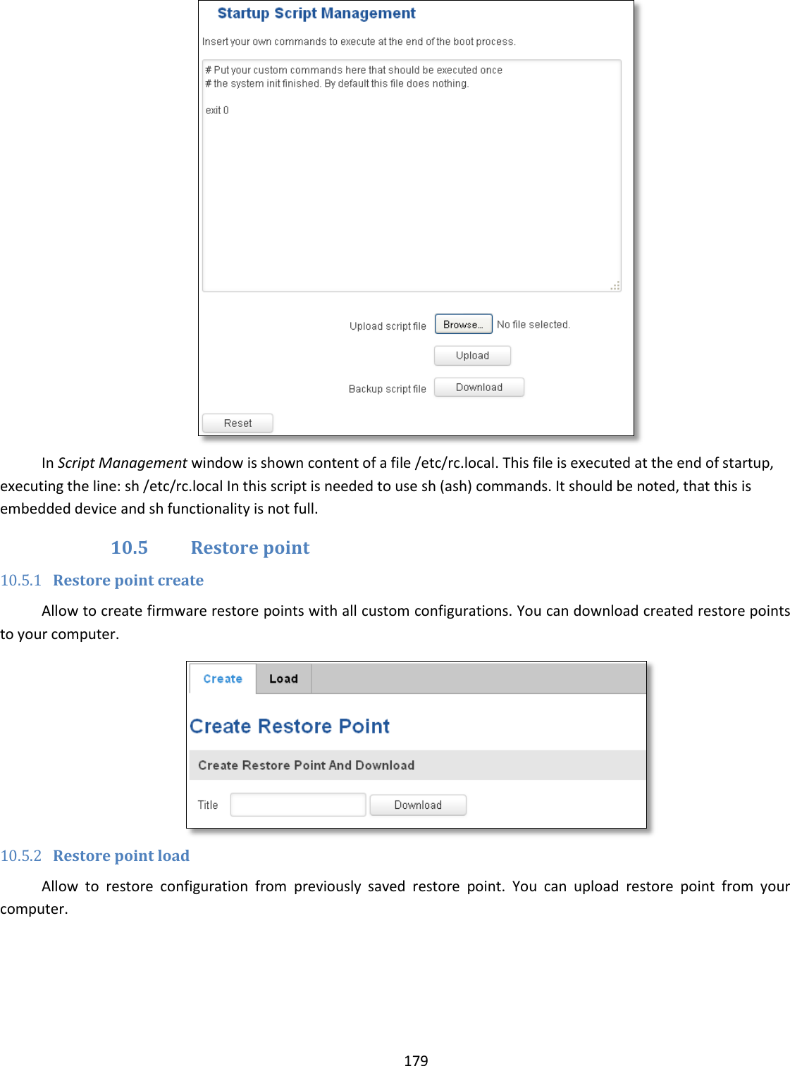
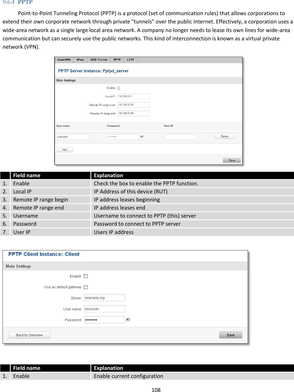
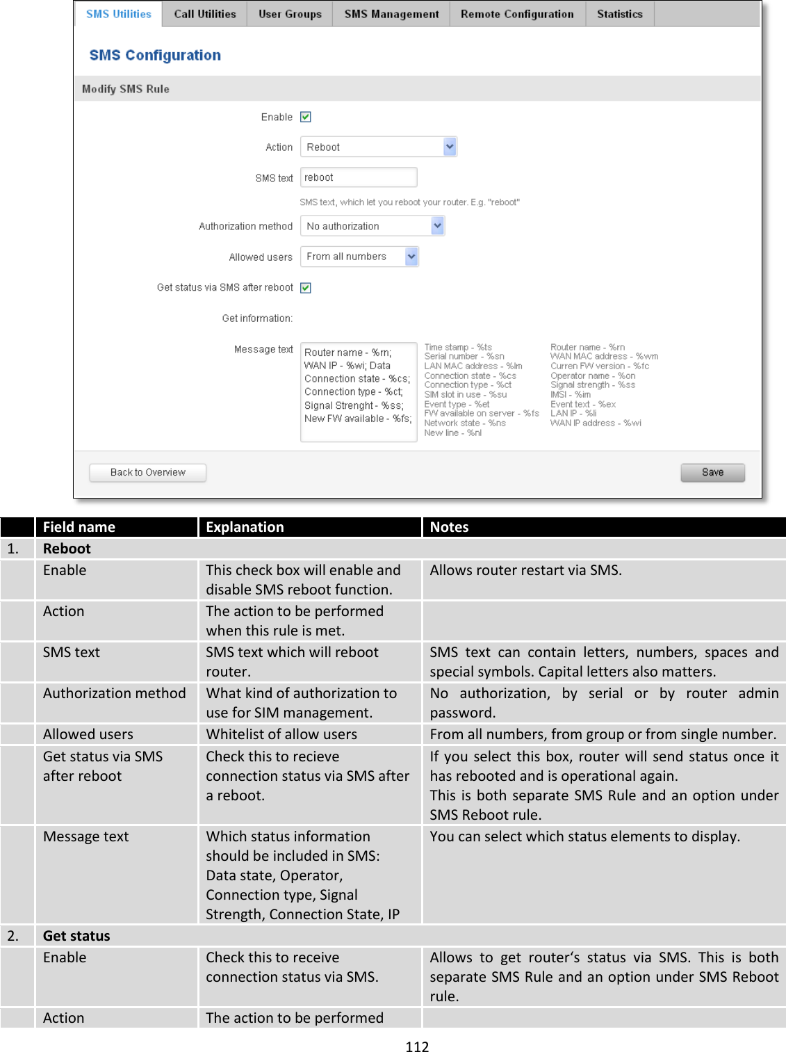
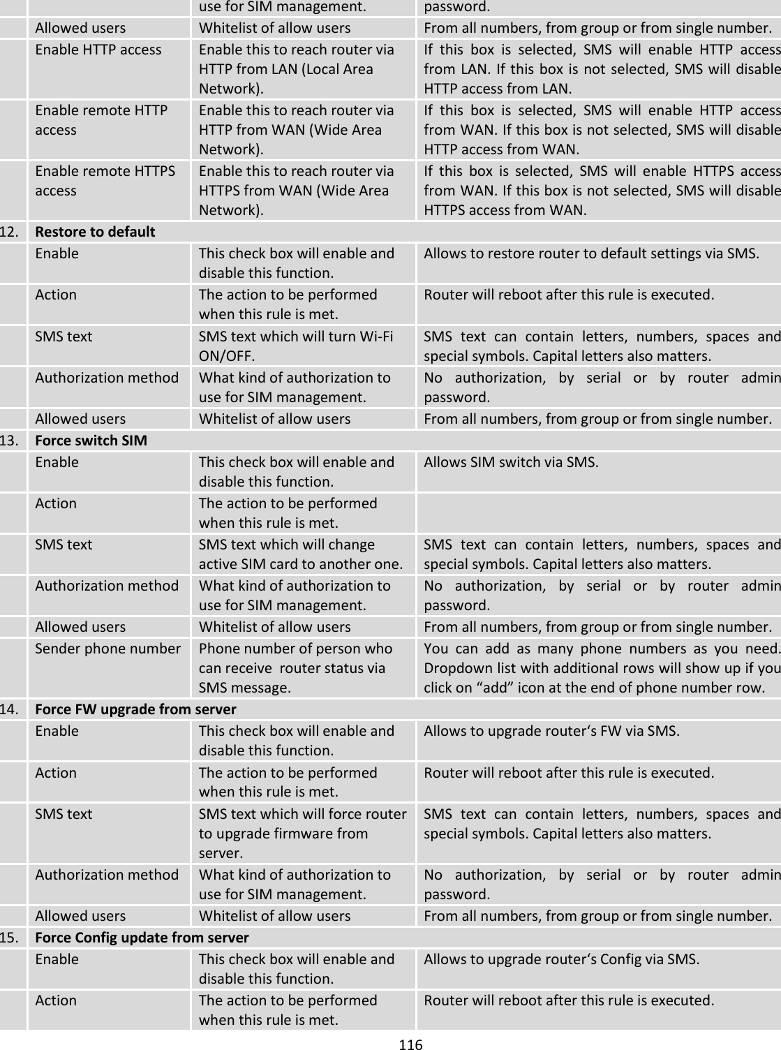
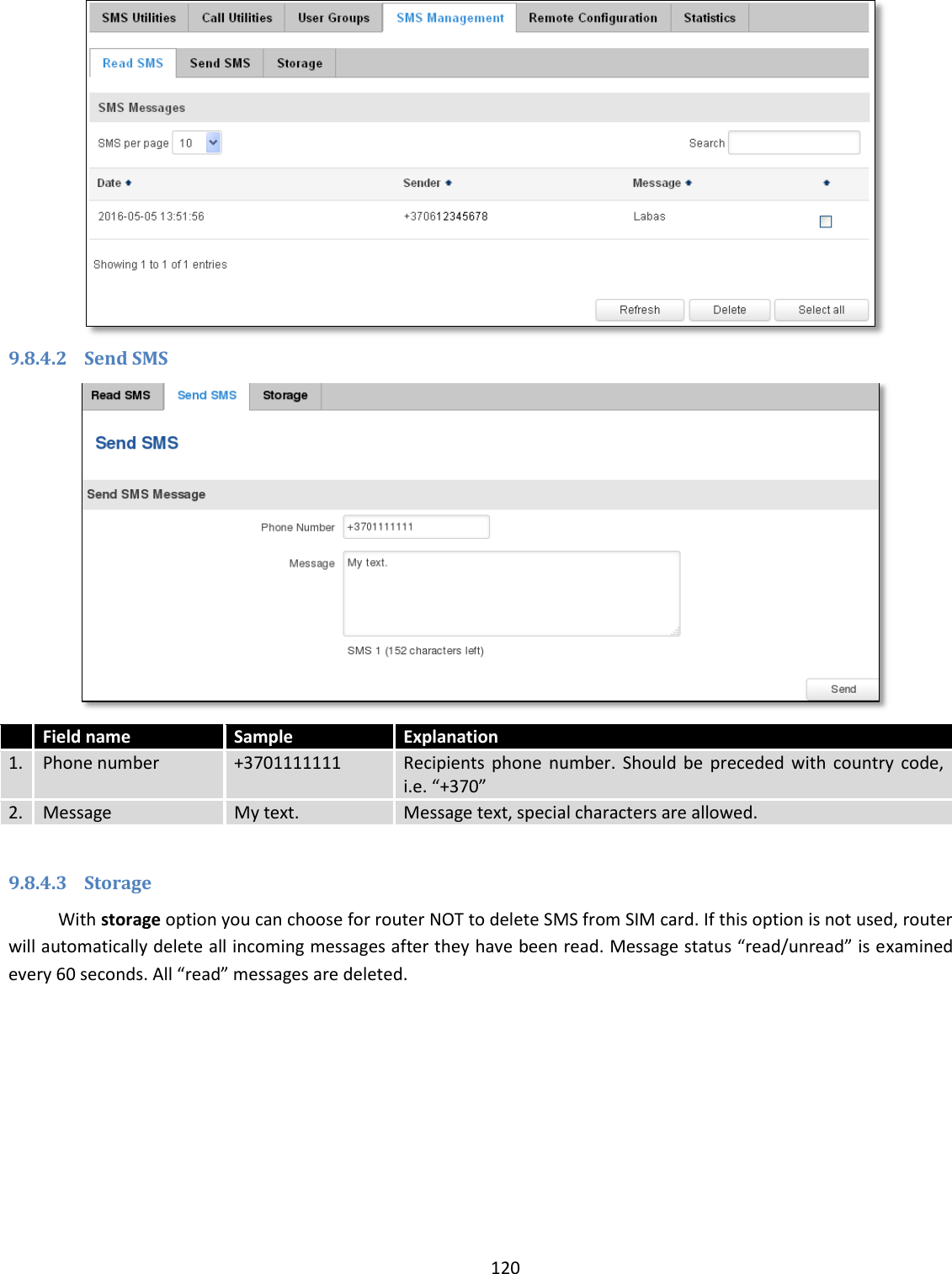
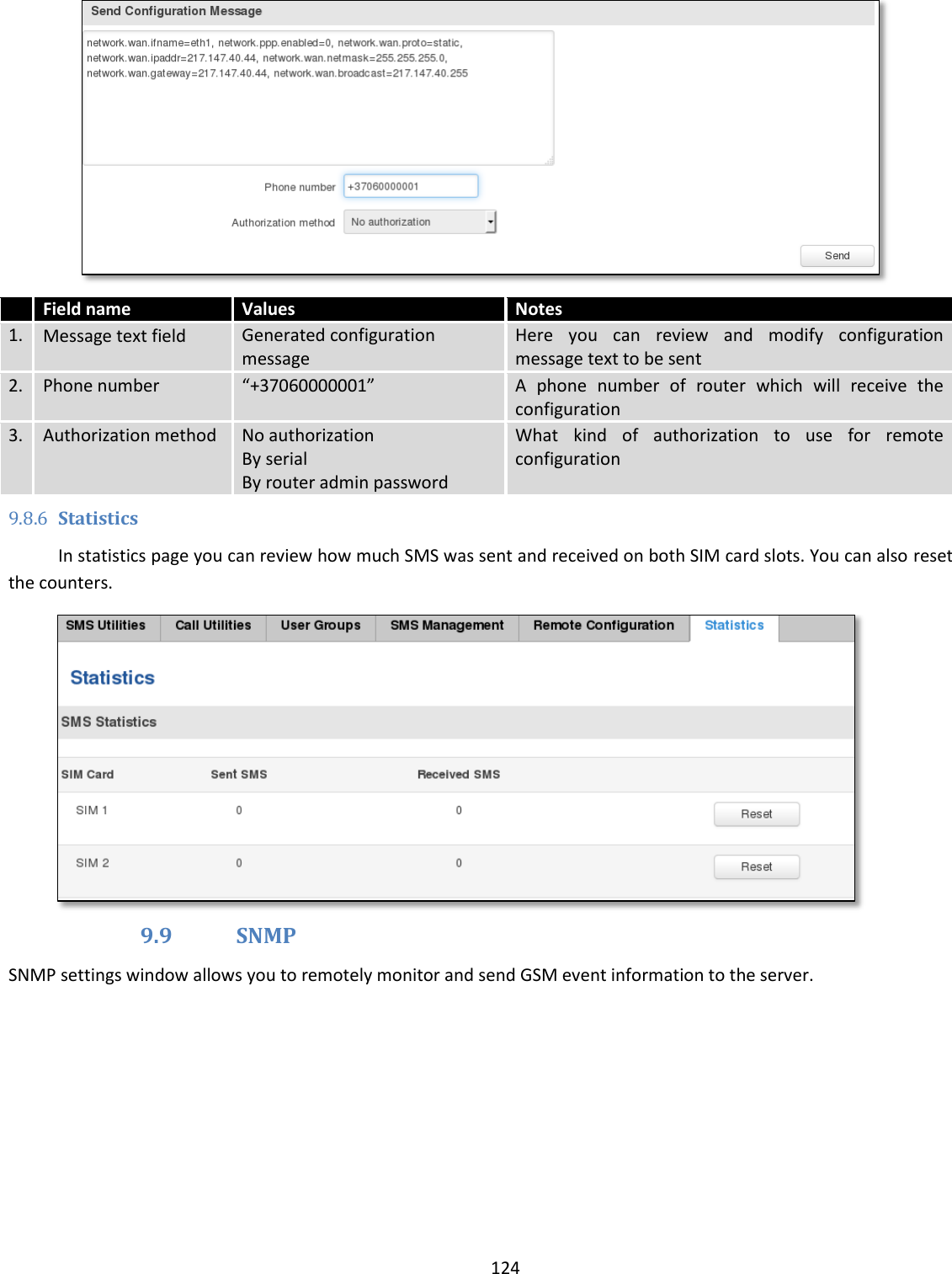
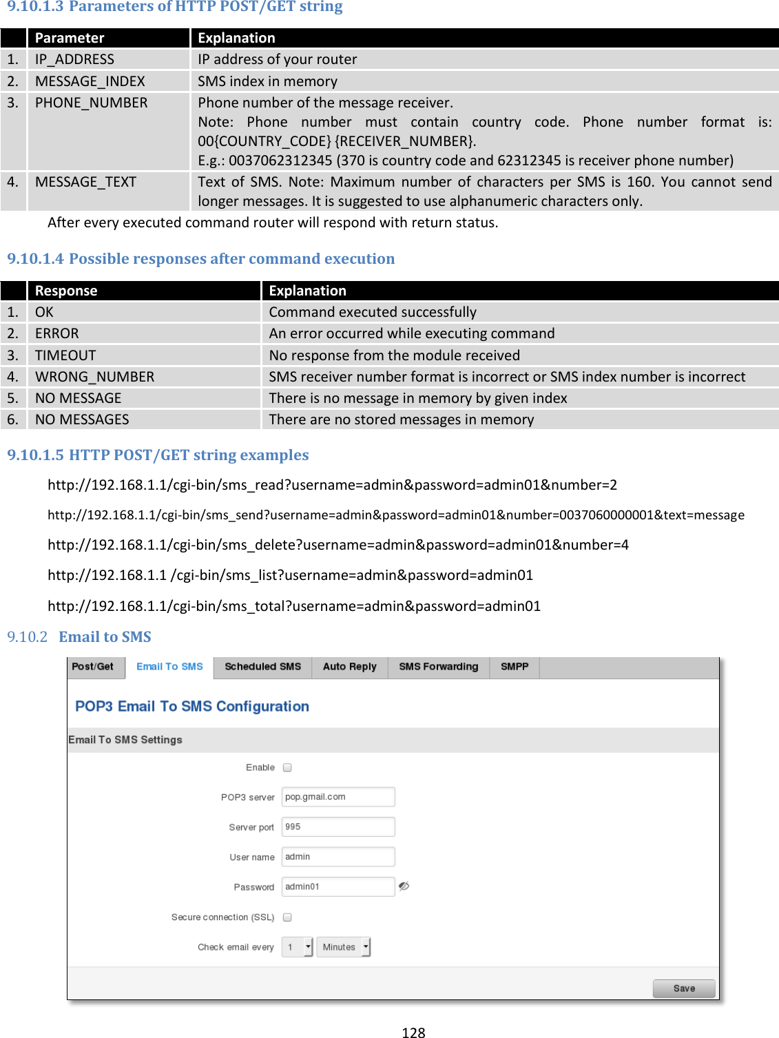
![107 Field name Explanation 1. Enabled Check the box to enable the GRE Tunnel function. 2. Remote endpoint IP address Specify remote WAN IP address. 3. Remote network IP address of LAN network on the remote device. 4. Remote network netmask Network of LAN network on the remote device. Range [0-32]. 5. Local tunnel IP Local virtual IP address. Cannot be in the same subnet as LAN network. 6. Local tunnel netmask Network of local virtual IP address. Range [0-32] 7. MTU Specify the maximum transmission unit (MTU) of a communications protocol of a layer in bytes. 8. TTL Specify the fixed time-to-live (TTL) value on tunneled packets [0-255]. The 0 is a special value meaning that packets inherit the TTL value. 9. PMTUD Check the box to enable the Path Maximum Transmission Unit Discovery (PMTUD) status on this tunnel. 10. Enable Keep alive It gives the ability for one side to originate and receive keep alive packets to and from a remote router even if the remote router does not support GRE keep alive. 11. Keep Alive host Keep Alive host IP address. Preferably IP address which belongs to the LAN network on the remote device. 12. Keep Alive interval Time interval for Keep Alive. Range [0 - 255].](https://usermanual.wiki/UAB-Teltonika/RUT955A.User-Manual-2/User-Guide-4043742-Page-17.png)
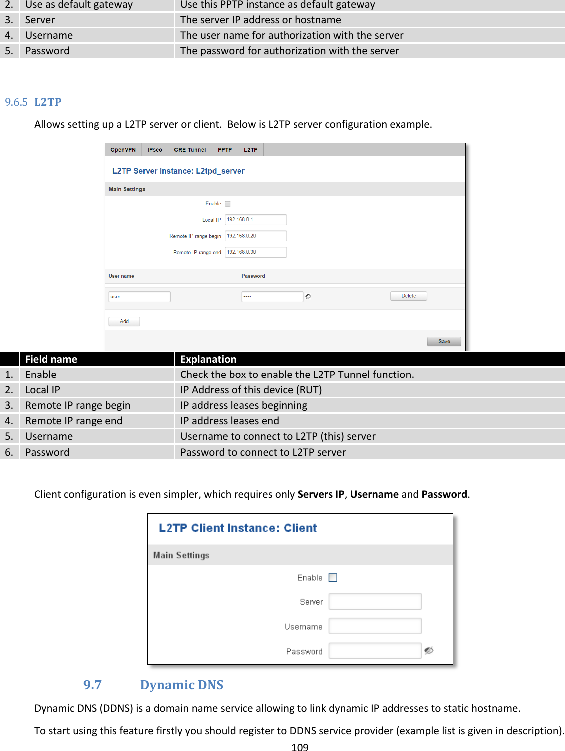
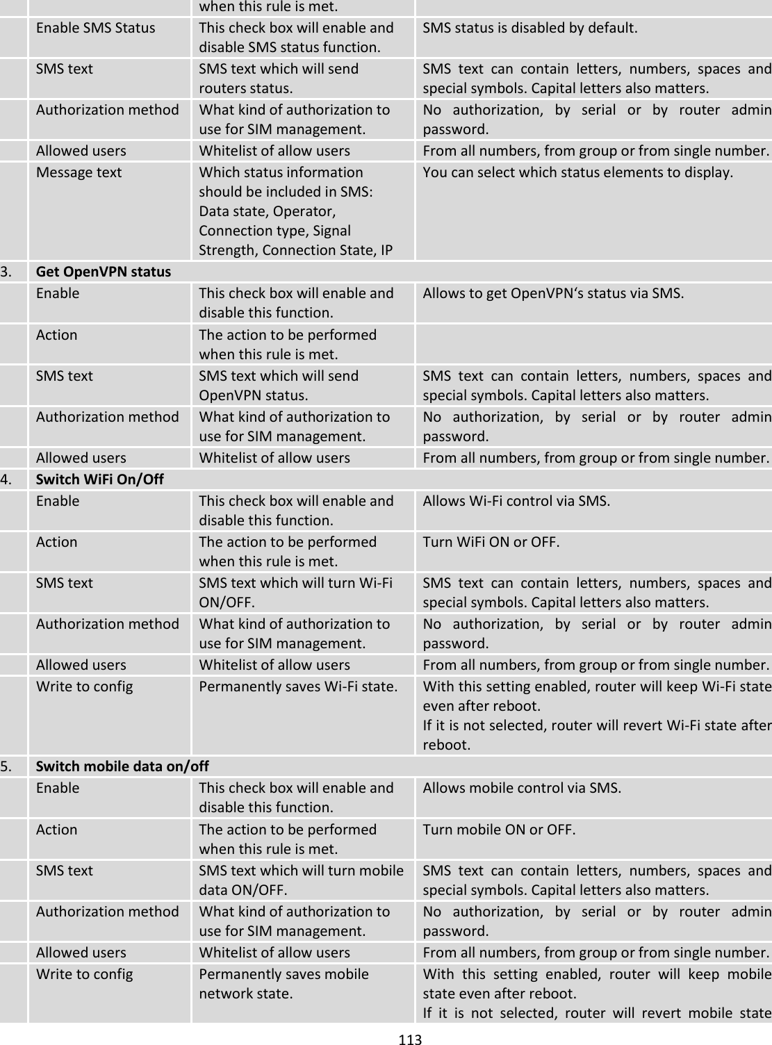
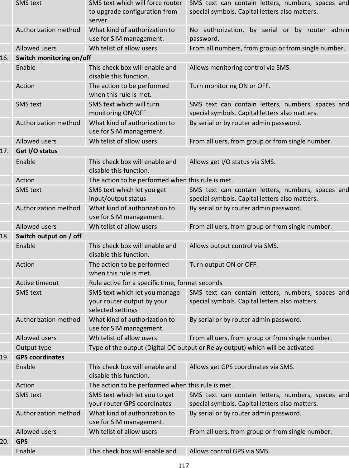
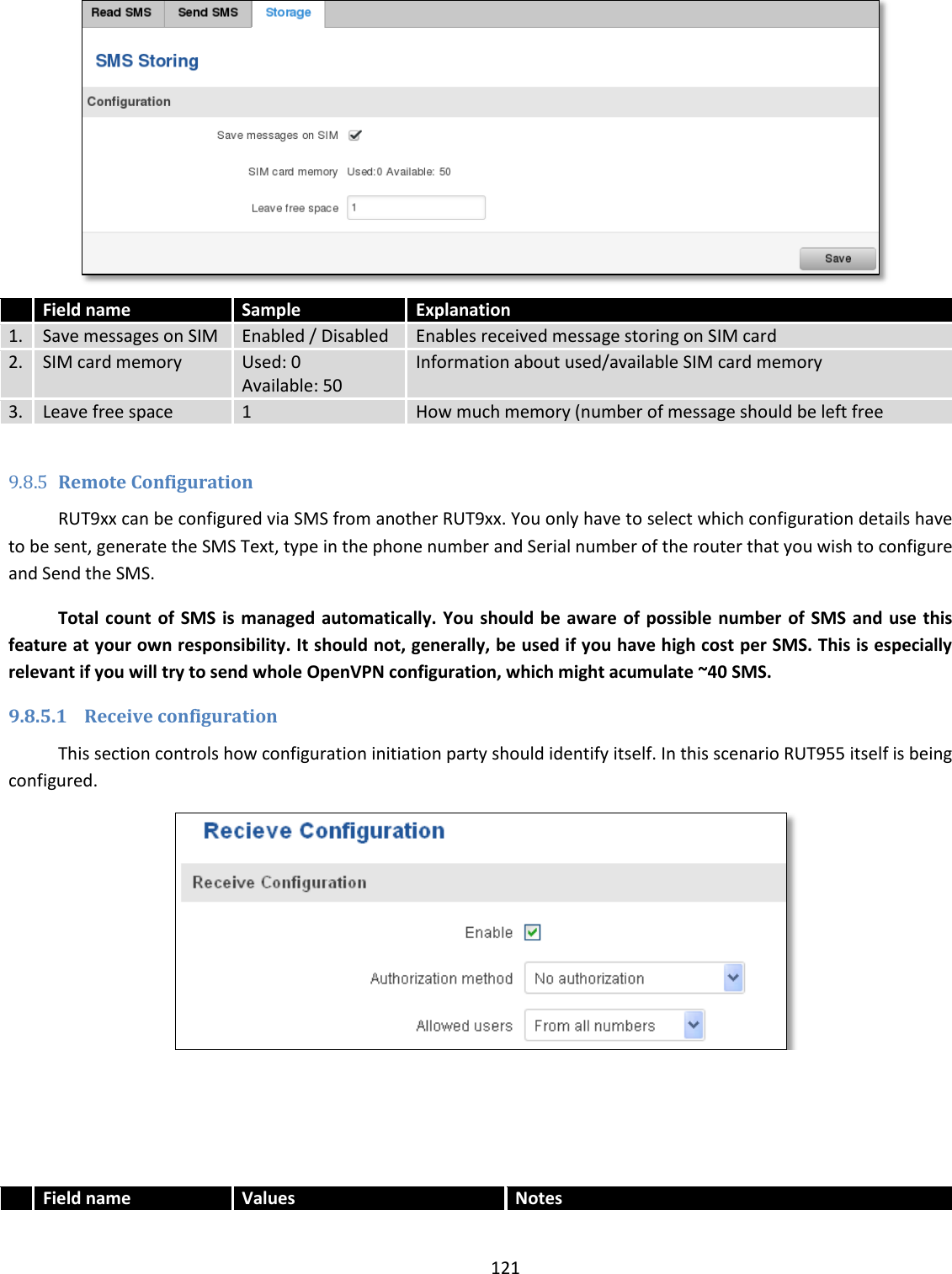
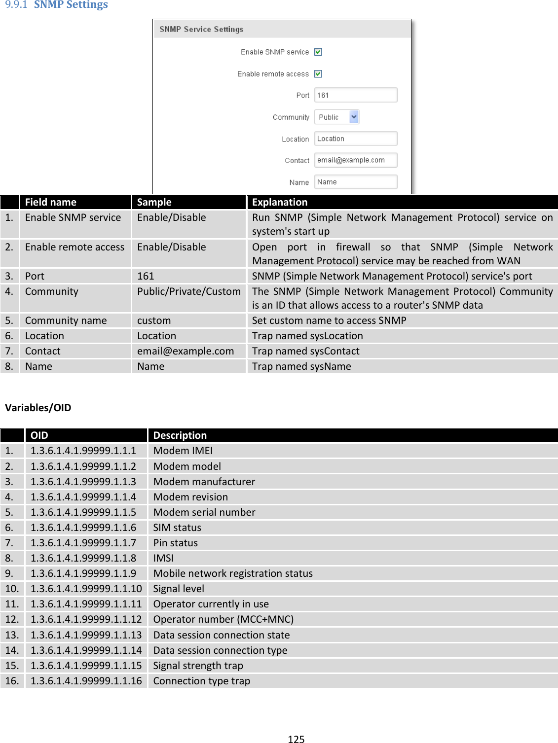
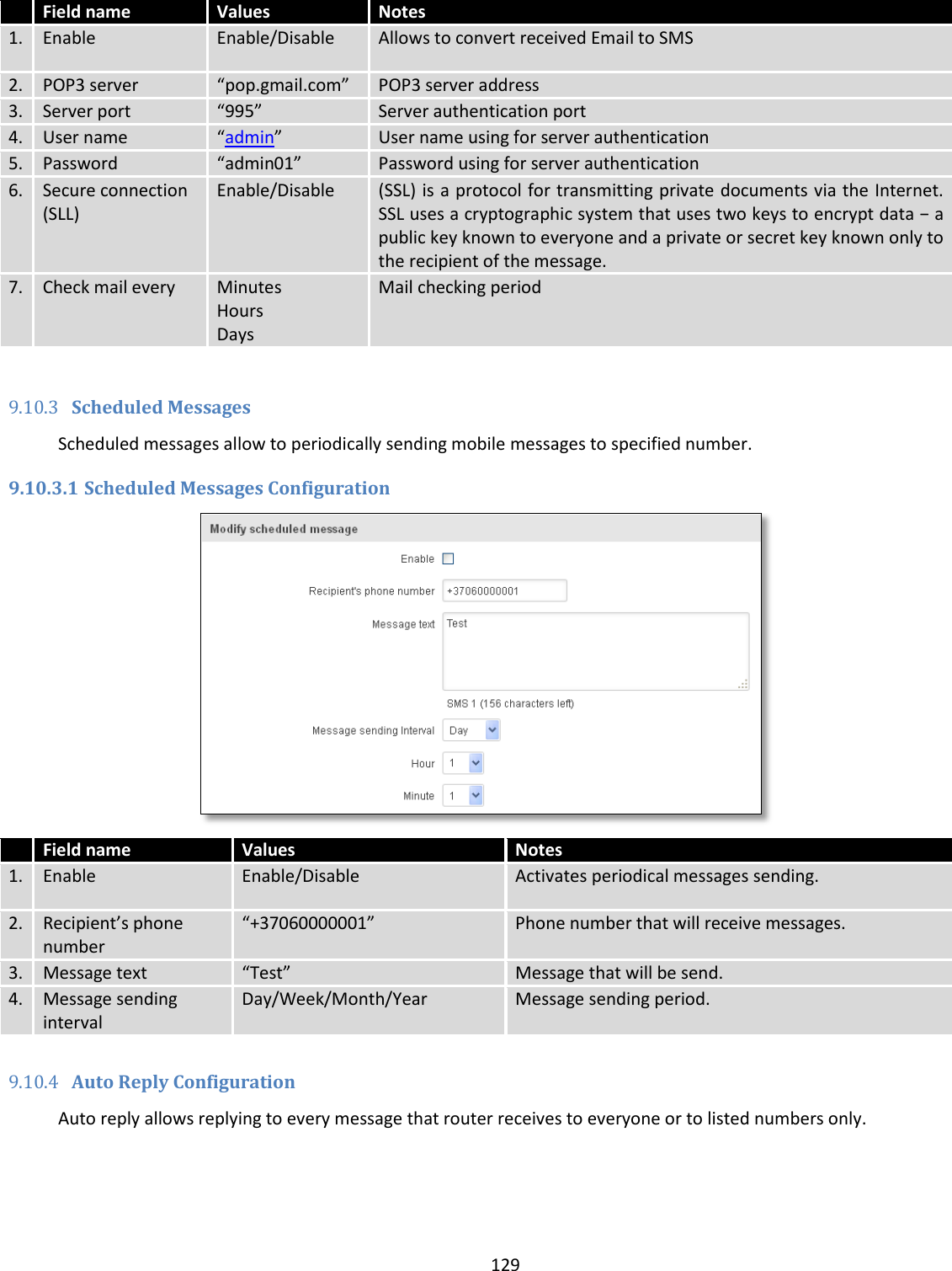
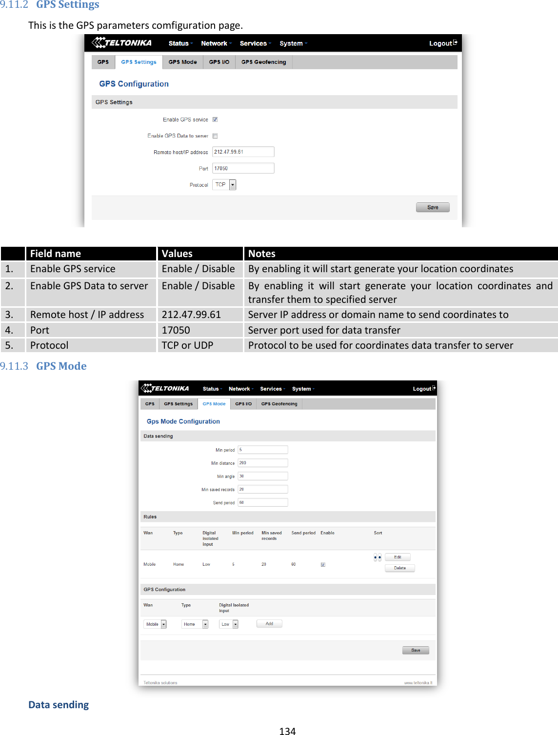
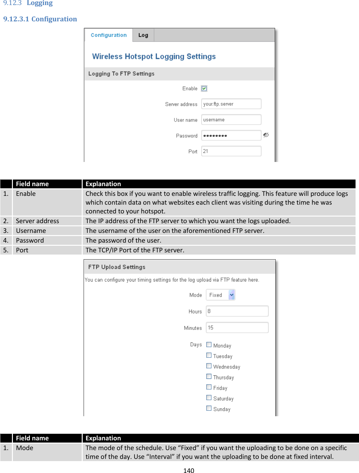
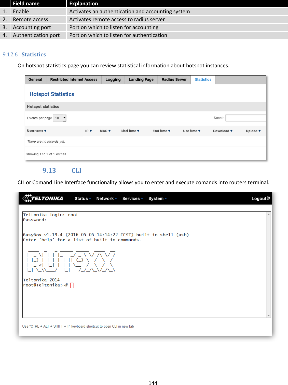
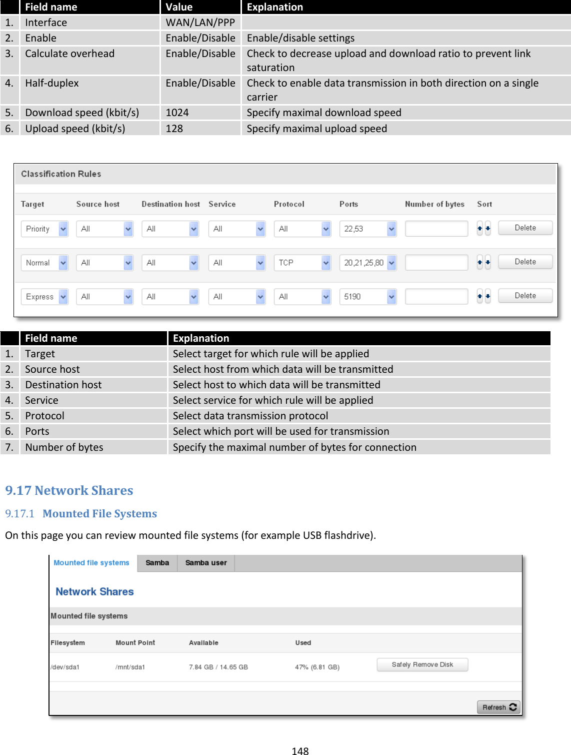
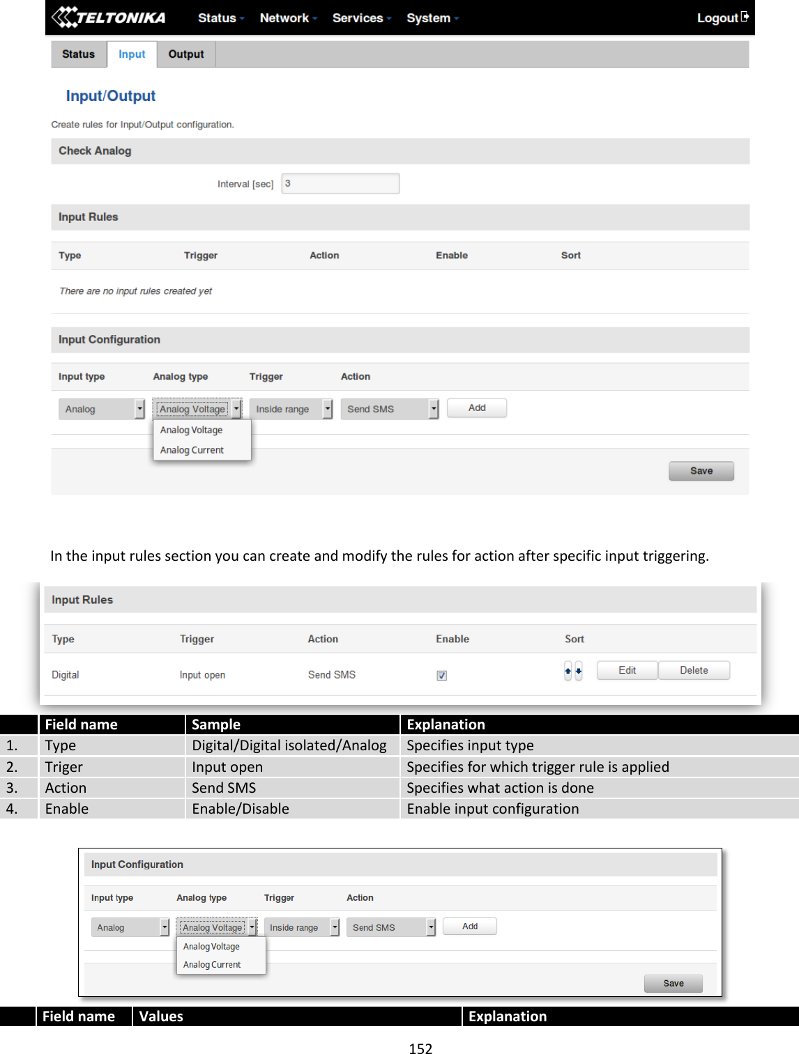
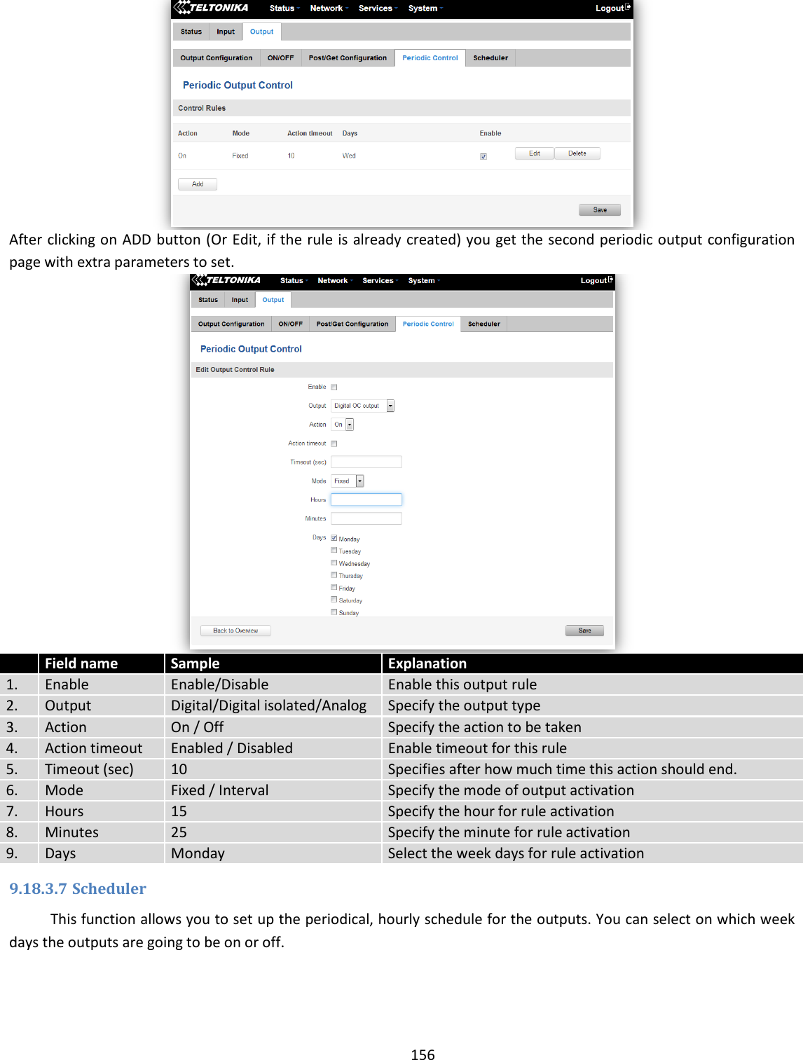
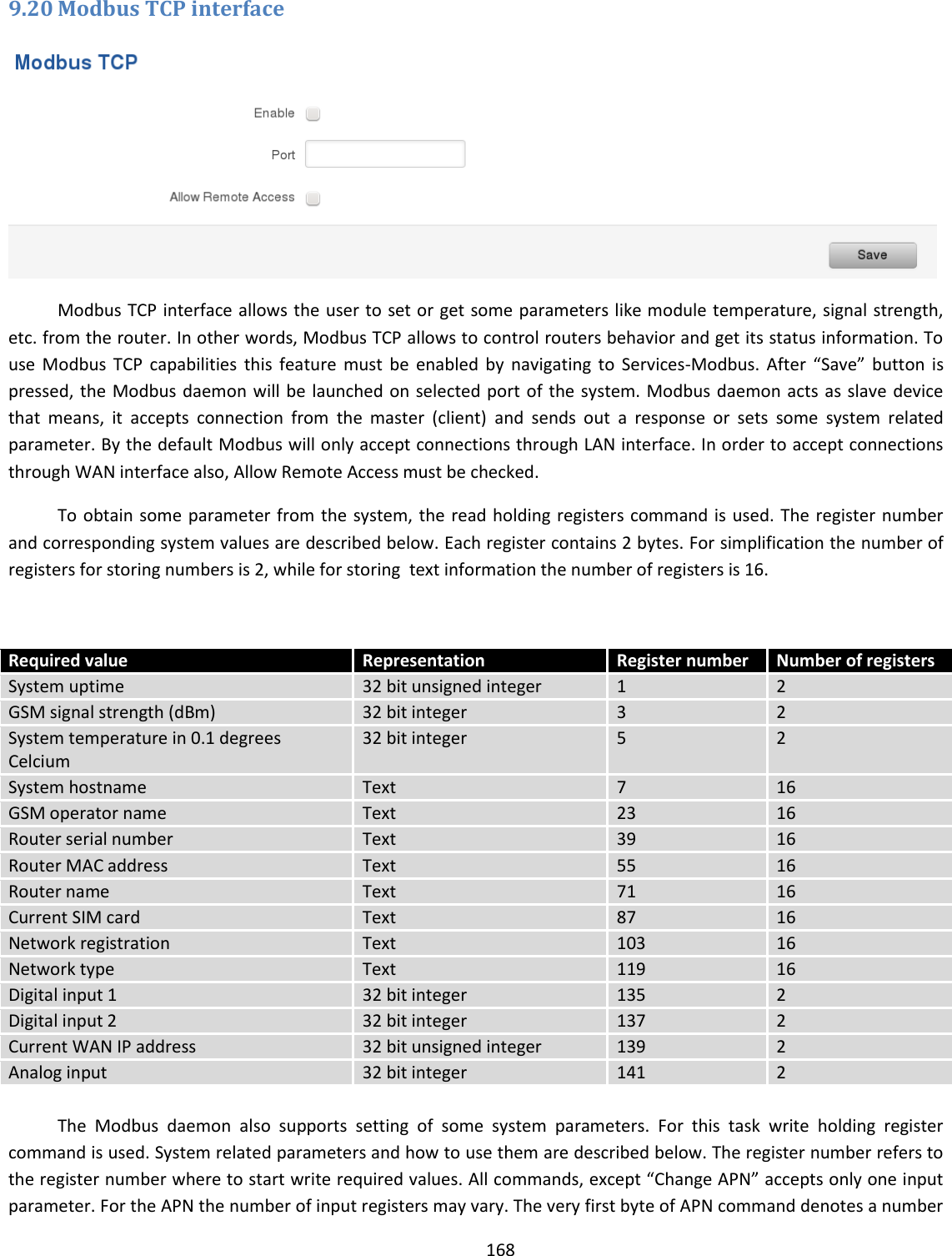
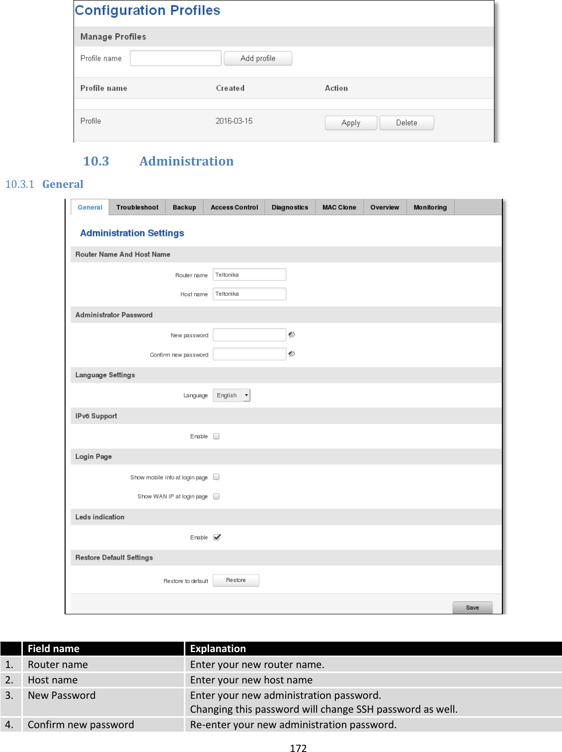
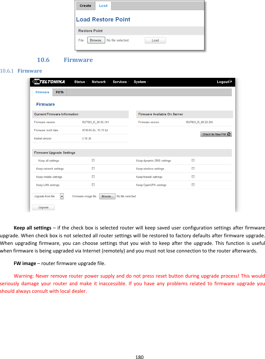
![133 9.10.6 SMPP Field name Values Explanation 1. Enable Enable/Disable Enables SMPP server 2. User name admin User name for authentication on SMPP server 3. Password ●●●●●●● Password for authentication on SMPP server 4. Server port 7777 A port will be used for SMPP server communications. Allowed all not used ports [0-65535] 9.11 GPS 9.11.1 GPS On this page you can view your current coordinates and position on map](https://usermanual.wiki/UAB-Teltonika/RUT955A.User-Manual-2/User-Guide-4043742-Page-43.png)