UAB Teltonika TM2500TLT GSM/GPRS/GNSS/BLUETOOTH module User Manual Antenna Datasheet Addendum OEM Manual
UAB Teltonika GSM/GPRS/GNSS/BLUETOOTH module Antenna Datasheet Addendum OEM Manual
Contents
- 1. Users Manual
- 2. Antenna Datasheet Addendum OEM Manual
- 3. User Manual
- 4. User Manual OEM BT Antenna Datasheet
Antenna Datasheet Addendum OEM Manual

DATA SHEET
WIRELESS COMPONENTS
Ceramic Chip Antenna
ANT3216A063R2400A
2.4 - 2.5GH
Z
3216 Series
Product
Specification – February 19, 2014 V.0
www.yageo.com
Feb. 19, 2014 V0
WIRELESS COMPONENTS
2
6
Product specification
Ceramic Chip Antenna
FEATURES
Compact size
Omni-directional Radiation
Tape & reel automaic
mounting
Reflow process compatible
RoHS compliant
APPLICATIONS
2.4GHz WiFi device
Bluetooth gadget
Zigbee device
ISM band equipment
ORDERING INFORMATIO
N
All part number
s are identified by the series, packing type, material, size,
antenna
type, working frequency and packing quantity.
PART NUMBER
ANT 3216
A 063 R 2400A
(1) (2) (3) (4) (5) (6)
(1) PRODUCT
ANT = Antenna
(2) SIZE
3216 = 3.2 × 1.6 mm
(3)
ANTENNA TYPE
L,F,A = Chip Antenna
(4)
SERIAL NO.
063
(5)
PACKING STYLE
R = Tape and Reel
(6) WORKING FREQUENC
Y
2400 = 2.4GHz
PHYCOMP CTC
CAN4311212632453K
12NC
431121263245
www.yageo.com
Feb. 19, 2014 V0
WIRELESS COMPONENTS
3
6
Product specification
Ceramic Chip Antenna
SPECIFICATION
DESCRIPTION
VALUE
Centre
Frequency 2.45 G
Hz
Bandwidth
230 MHz(Typ.)
Return Loo
s
10 dB min
Polarization
Linear
Azimuth Beamwidth
Omni-
directional
Peak Gain
1.69 dBi(Typ.)
Impedance
50
Ω
Operating Temperature
- 40~105
℃
Maximum Power
1 W
Termination
Ni/Sn (Environmentally-
Friendly Leadless)
Resistance to Soldering Heats
260℃
, 10sec.
NOTE
1. The specification is defined on Yageo evaluation board
Ta b l e 1
O
O
U
UT
TL
LI
IN
NE
ES
S
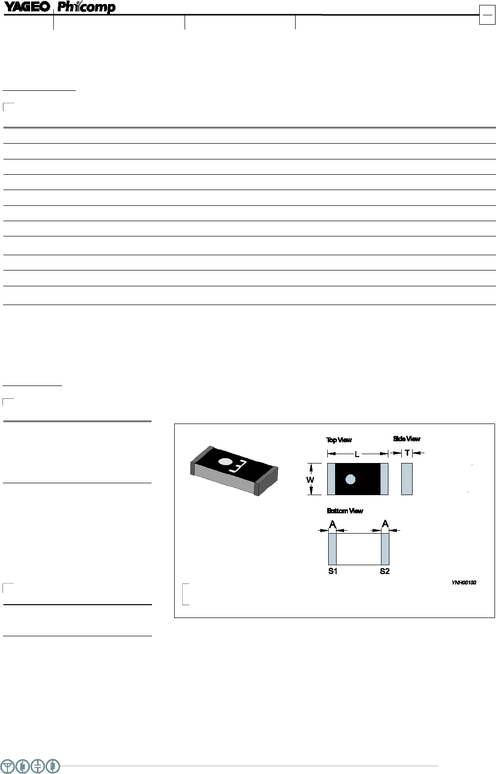
Fi g. 1 Antenna outlines
DIMENSIONS
DIMENSION
L (
mm) 3.05 ± 0.10
W (
mm) 1.55 ± 0.10
T
(mm) 0.55 ± 0.10
A
(mm) 0.40 ± 0.10
Table 2 Machinical Dimension
TERMINAL NAME
FUNCTION
S1
Feeding Point
S2
GND
Table 3 Termination configuration
www.yageo.com
Feb. 19, 2014 V0
WIRELESS COMPONENTS
4
6
Product specification
Ceramic Chip Antenna
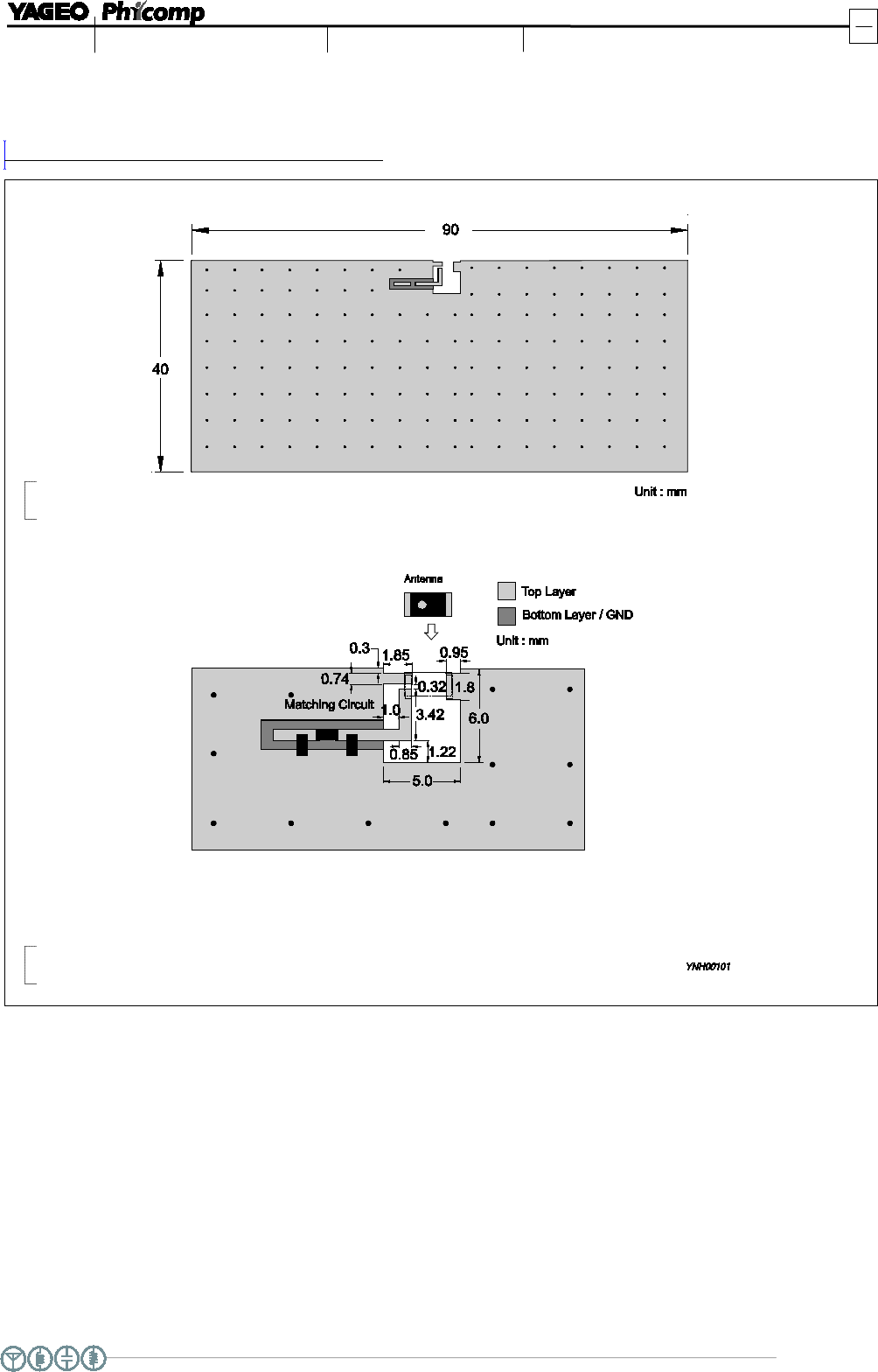
Fi g. 2 Outlook and dimension of evaluation board
REFERENCE DESIGN OF
EVALUATION BOARD
Fi g. 3 Details of soldering Pad
www.yageo.com
Feb. 19, 2014 V0
WIRELESS COMPONENTS
5
6
Product specification
Ceramic Chip Antenna
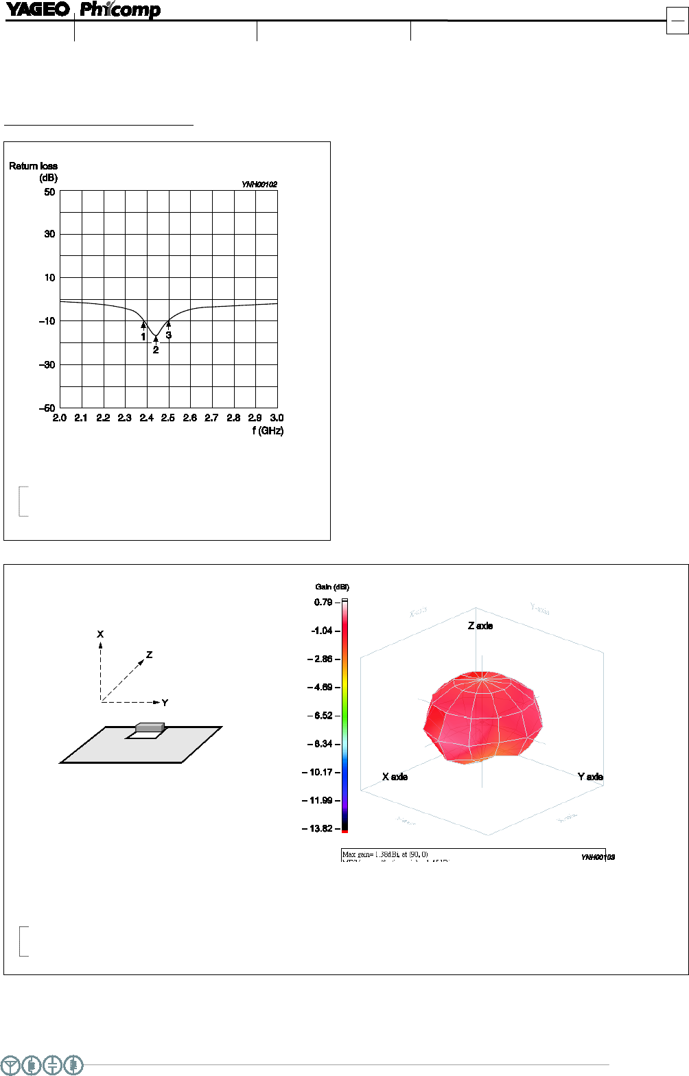
Fi g. 4 Return loss
Fi g. 5 Radiation pattern
Frequency= 2.45 GHz
Max gain =
1.69 dBi, at (90,0)
MEG (mean effective gain)=
-1.00 dBi
Directivity (dB) =
2.18
Efficiency =
- 0.49dB, 89.33%
ELECTRICAL PERFORMAN
CES
Evaluation board and XYZ direction
Marker data
1.
2.39GHz, -10dB
2.
2.45GHz, -16.48
dB
3.
2.50GHz, -10dB

www.yageo.com
Feb. 19, 2014 V0
WIRELESS COMPONENTS
6
6
Product specification
Ceramic Chip Antenna
REVISION HISTORY
REVISION
DATE
CHANGE NOTIFICATION
DESCRIPTION
Version 0
F
eb. 19, 2014
-
-
New data sheet for SMD type antenna, 2.45GHz application,
3216 series PIFA mode