UAB Teltonika TM2500TLT GSM/GPRS/GNSS/BLUETOOTH module User Manual
UAB Teltonika GSM/GPRS/GNSS/BLUETOOTH module Users Manual
Contents
Users Manual
Vilnius,
1/23
TM2500
GSM/GPRS/GNSS/BLUETOOTH module
USER MANUAL
Version 0.2

Vilnius,
2/23
FOR OEM OR INTEGRATORS ONLY: This module is limited to OEM installation
only and must not be sold to end-users.
Copyright
TELTONIKA is a registered trademark of UAB TELTONIKA.
Copyright © 2016 UAB TELTONIKA. All rights reserved.
No part of this publication may be reproduced or distributed in any form or by any means, or
stored in a database or retrieval system, without the prior written permission of the publisher.
UAB TELTONIKA reserves the right to make changes in technical and product specifications
without provisional notification.
OEM integrators must be instructed to ensure that the end-user has no manual instructions
to remove or install the device.
The end-user can not remove or install this module to any other devices.

Vilnius,
3/23
INTRODUCTION...................................................................................................................................4
1.1 Contactinformation,Support...............................................................................................4
1.2 RelatedDocuments...............................................................................................................4
1.3 OVERVIEW.............................................................................................................................4
1.4 SCOPEOFTHEPRODUCT.......................................................................................................5
1.5 CERTIFICATION......................................................................................................................5
MODEMfeatures................................................................................................................................5
GSM/GPRSRFFeatures.......................................................................................................................6
Bluetoothfeatures..............................................................................................................................7
FMFeatures........................................................................................................................................8
GPSfeatures........................................................................................................................................8
ApplicationFunctions.........................................................................................................................9
1.6 ApplicationModesIntroduction...........................................................................................9
POWERSUPPLY...................................................................................................................................9
1.7 PowerSupplyRequirements.................................................................................................9
1.8 PowerFeaturesofGSMPart.................................................................................................9
1.9 SLEEPMode.........................................................................................................................10
1.10 OperatingModesofGNSSPart.......................................................................................11
1.11 Powerconsumption........................................................................................................11
1.12 PowerSaving...................................................................................................................12
1.13 Minimumfunctionalitymode.........................................................................................12
1.14 RFOutoutPower.............................................................................................................13
1.15 RFReceivingSensitivity...................................................................................................14
1.16 OperatingFrequencies....................................................................................................14
DIGITALLEVELSPECIFICATIONS........................................................................................................14
1.17 DCcharacteristics............................................................................................................14
CommunicatewithModule..............................................................................................................15

Vilnius,
4/23
Standards and Regulatory Compliance..........................................................................................19
Standardsandcertification...............................................................................................................19
FCCcertificationrequirements.........................................................................................................20
FCCRFexposurerequirements.........................................................................................................22
ChangeLog........................................................................................................................................23
INTRODUCTION
1.1 Contactinformation,Support
TheTM25HardwareUserManualcontainsallinformationnecessaryforasuccessful
integrationoftheGSM/GPRSmoduleTM25intothecustomerapplications.
ThisdocumentisintendedforTeltonikacustomerstosupportapplicationandengineering
effortsthatusetheproductsdesignedbyTeltonika.Thedocumentcontainsadescription
interfacespresentonthemodule.
Contactinformation,Support
Forgeneralcontact,technicalsupport,toreportdocumentationerrorsandmanuals,
contactTeltonikaTechnicalSupportCenterat:support@teltonika.lt
1.2 RelatedDocuments
At_commands_Manual
1.3 OVERVIEW
ThisdocumentdescribesTeltonikaGSM/GPRS/GPS/BLUETOOTHmodule:mechanicaland
electricalparameters,pin‐outsdescriptions,hardwarecommands,powersupply
parameters,I/Oandportdescriptions,mountingandpackinginformationaswellasthe
designrulesofthemoduleintegrationwithinuserapplication.
Thedocumentcontainssomehardwaresolutionsfordevelopingaproductwiththe
TeltonikaTM25module,suggestedhardwaresolutionscanbetakenasabasefor
developingtheproductwithTeltonikaTM25module.
Vilnius,
5/23
1.4 SCOPEOFTHEPRODUCT
TM25isaQuad‐bandGSM/GPS/BLUETOOTHmodule,withtinyprofileof17mmx17mmx2.5mm.
Moduleworksat850MHz,900MHz,1800MHz,1900MHzfrequencies.TM25containsGPRSmulti‐
slotclass12andsupportstheGPRScodingschemesCS‐1,CS‐2,CS‐3,CS‐4.
1.5 CERTIFICATION
TM25GSM/GPRS/GPS/BLUETOOTHmoduleiscertifiedbyCEapprovalreportRadio&
TelecommunicationsTerminalEquipmentDirective(R&TTED)report.
Hereby,TeltonikadeclaresthatthisGSM/GPRS/GPS/BLUETOOTHDataModuleisin
compliancewiththeessentialrequirementsandotherrelevantprovisionsofDirective
1999/5/EC.Thedirectivesthatarefollowedforthisdatamodulearedescribedbelow:
MODEMfeatures
Radiointerfaceandbasebandfront‐end
DigitalPMdatapathwithbasebandfront‐end
Highdynamicrangedelta‐sigmaADCconvertsthedownlinkanalogIandQsignalto
digitalbaseband.
10‐bitD/AconverterforAutomaticPowerControl(APC).
ProgrammableradioRxfilterswithadaptivegaincontrol.
DedicatedRxfilterforFBacquisition.
6‐pinBasebandParallelInterface(BPI)withprogrammabledrivingstrength
Supportsmulti‐band
VoiceandmodemCODEC
Dialtonegeneration
Voicememo
Noisereduction
Echosuppression
Advancedsidetoneoscillationreduction
Digitalsidetonegeneratorwithprogrammablegain
Twoprogrammableacousticcompensationfilters
Vilnius,
6/23
SupportsGSM/GPRSmodem
GSMquadvocodersforadaptivemultirate(AMR),enhancedfullrate(EFR),fullrate
(FR)andhalfrate(HF)
GSMchannelcoding,equaluzationandA5/1,A5/2andA5/3ciphering
GPRSGEA1,GEA2andGEAciphering
GPRSpacketswitcheddatawithCS1/CS2/CS3/CS4codingschemes
GPRSClass12
SupportsSAIC(singleantennainterfacecancelltaion)technology
SupportsVAMOS(VoiceserviesoverAdaptivemulti‐userchannelsonOneSlot).
Voiceinterfaceandvoicefront‐end
Microphoneinputhasonelow‐noiseamplifierwithprogrammablegainAutomatic
GainControl(AGC)mechanisms
Voicepoweramplifierwithprogrammablegain
2ndorderSigma‐DeltaA/Dconverterforvoiceuplinkpath
SharesD/Aconverterwithaudioplaybackpath
Supportsfull‐duplexhands‐freeoperation
CompliantwithGSM03.50
GSM/GPRSRFFeatures
Receiver
Dualsingle‐endedLNAssupportQuadbandQuadratureRFmixer
Fullyintegratedchannelfilter
HighdynamicrangeADC
‐12dBPGAgainwith6dBgainstep
Transmitter
Transmitteroutputssupportquadbands.
HighlypreciseandlownoiseRFtransmitterforGSM/GPRSapplications
Vilnius,
7/23
Frequencysynthesizer
Programmablefractional‐Nsynthesizer
IntegratedwiderangeRFVCO
Integratedloopfilter
Fastsettlingtimesuitableformulti‐slotGPRSapplications.
Digitally‐ControlledCrystalOscillator(DCXO)
Two‐pin25MHzcrystaloscillator
On‐chipprogrammablecapacitorarrayforcoarse‐tuning
On‐chipprogrammablecapacitorarrayforfine‐tuning
Lowpowermodesupports32Kcrystalremoval
Bluetoothfeatures
Radiofeature
FullycompliantwithBluetoothspecification3.0
Lowout‐of‐bandspuriousemissionssupportsimultaneousoperationwithGPSand
GM\SM/GPRSworldwideradiosystems
Low‐IFarchitecturewithhighdegreeoflinearityandhighorderchannelfilter
FullyintegratedPAprovides7.5dBmoutputpower
‐95dBmsensitivitywithexcellentinterferencerejectionperformance
HardwareAGCdynamicallyadjustsreceiverperformanceinchangingenvironments
Basebandfeatures
Upto4simultaneousactiveACLlinks
Upto1simultaneousSCOoreSCOlinkwithCVSDcoding
SupportseSCO
Scatternetsupport:Uptopiconetssimultaneouslywithbackgroundinquiry/page
scan
Supportssniffmode
AFHandPTAcollaborativesupportforWLAN/BTcoexistence
Idlemodeandsleepmodeenablesultra‐lowpowerconsumption

Vilnius,
8/23
SupportsPCMinterfaceandbuilt‐inprogrammabletranscodersforlinearvoicewith
re‐transmission
Built‐inhardwaremodemengineforaccesscodecorrection,headererrorcorrection,
forwarderrorcorrection,CRC,whiteningandencryption
Channelqualitydrivendatarateadaptation
ChannelassessmentforAFH
Platformfeatures
EmbeddedprocessorforBluetoothprotocolstackwithbuild‐inmemorysystem
FullyverifiedROMbasedsystemwithcodepatchforfeatureenhancement
FMFeatures
65‐108MHzworldwideFMbandswith50KHztuningstep
SupportsRDS/RBDSradiodatasystem
Digitalstereodemodulator
AdaptiveFMdemodulatorforbothhigh‐andlow‐qualityscenarios
Lowsensitivitylevelwithsuperiorinterferencerejection
Programmablede‐emphasis(bypass/50S/75S)
Stereophonicmultiplexsignal(MPX)signaldetectionanddemodulation
Superiorstereonoisereductionandsoftmutevolumecontrol
Mono/stereoblending
Audiosensitivity3dBuVemf(SINAD=26dB)
AudioSINAD>=60dB
SupportsAnti‐jammingalgorithm
Supportsshortantenna
GPSfeatures
GPS/GLONASS/GALILEO/BEIDOUreceiver
Supportsmulti‐GNSS,QZSS,SBASranging
SupportsWAAS,EGNOS,MSAS,GAGAN
12multi‐toneactiveinterferencecancellers
Vilnius,
9/23
RTCMready
Indoorandoutdoormulti‐pathdetectionandcompensation
SupportsFCCE911complianceandA‐GPS
Max.fixedupdaterateupto10Hz
ApplicationFunctions
TM2500isandSMDtypemodulewith129LGApads.From129pads,28isGROUNDpads,14
Generalpurpose(GPIO)padsandotherpurposepins.
1.6 ApplicationModesIntroduction
TM2500moduleisintegratedwithGSM,GNSSandBLUETOOTHengineswhichcanworkasawhole
unit(all‐in‐onesolution)orworkindependently(stand‐alonesolution)accordingtocustomer
demands.
POWERSUPPLY
1.7 PowerSupplyRequirements
Theexternalpowermustbeconnectedtomodempowerpads.
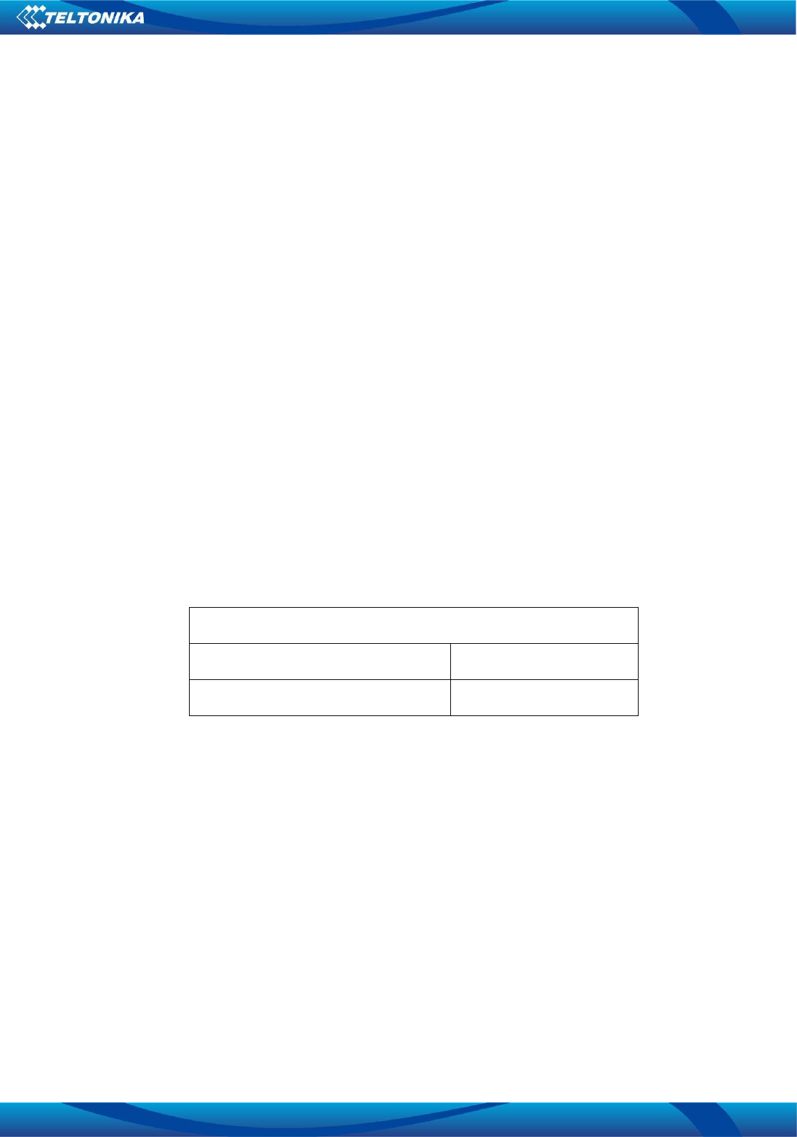
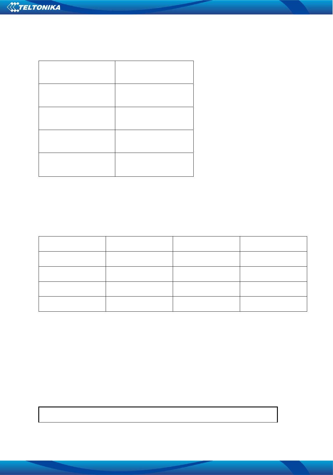
Table1TM2500Powersupplyrange
POWERSUPPLY
NominalSupplyVoltage+4.0V
NormalOperatingVoltagerange+3.4–4.2v
1.8 PowerFeaturesofGSMPart
ThepowersupplyoftheGSMpartisoneofthemainissuesinTM2500module,becauseGSM
modemcouldprovideshortcurrentburstsconsumptionuptomaximum2Aduringtransmissions.
TheoperatingVoltageRangemustneverbeexceeded.PowersupplyrangeofGSMpartisfrom3.3V
to4.6V.Specialcaremustbetakenwhendesigningtheapplicationspowersupplysectiontoavoid
havinganexcessivevoltagedrop.IfthevoltagedropisexceedingthelimitsitcouldcauseaPower
Offofthemodule.
TheVBATtraceshouldbewideenoughtoensurethatthereisnottoomuchvoltagedropduring
bursttransmission.Thewidthoftraceshouldbenolessthan2mm;andinprinciple,thelongerthe
VBATtrace,thewideritwillbe.

Vilnius,
10/23
1.8.1 ReferenceDesignforPowerSupply
Itissuggestedtocontrolthemodule’smainpowersupply(VBAT)viaLDOenablepintorestartthe
modulewhenthemodulebecomesabnormal.PowerswitchcircuitlikeP‐channelMOSFETswitch
circuitcanalsobeusedtocontrolVBAT.
1.8.2 PowerFeaturesofGNSSPart
PowersupplyrangeofGNSSpartisfrom2.8tomaximum4.3V.
1.8.3 Monitorpowersupply
TheATcommandAT+CBCcanbeusedtomonitorthesupplyvoltageoftheGSMpart.Theunitof
thedisplayedvoltageismV.Fordetails,pleaserefertoATcommandsmanual.
1.8.4 MinimumFunctionalityMode
MinimumfunctionalitymodereducesthefunctionalityoftheGSMparttoaminimumlevel.The
consumptionofthecurrentcanbeminimizedwhentheslowclockingmodeisactivatedatthesame
time.
ThemodeissetviatheAT+CFUNcommandwhichprovidesthechoiceofthefunctionalitylevels
<fun>=0,1,4
0:minimumfunctionality
1:fullfunctionality(default)
4:disablefrombothtransmittingandreceivingRFsignals
IftheGSMpartissettominimumfunctionalitybyAT+CFUN=0,theRFfunctionandSIMcard
function
wouldbedisabled.Inthiscase,theUARTportisstillaccessible,butallATcommandsrelatedwithRF
functionorSIMcardfunctionwillbeunavailable.
IftheGSMpartissetbythecommandAT+CFUN=4,theRFfunctionwillbedisabled,buttheUART
port
isstillactive.Inthiscase,allATcommandsrelatedwithRFfunctionwillbeunavailable.
AftertheGSMpartissetbyAT+CFUN=0orAT+CFUN=4,itcanreturntofullfunctionalitymodeby
AT+CFUN=1.
FormoredetailedinformationaboutAT+CFUN,pleaserefertoATcommandsmanualdocument.
1.9 SLEEPMode
SLEEPmodeisdisabledbydefault.ItcanbeenabledbyAT+ESLP=1andthepremiseisthatthe
GNSSispoweredoff.ThedefaultsettingisAT+ESLP=0,andinthismode,theGSMpartcannotenter
SLEEPmode.
WhentheGSMpartissetbythecommandAT+ESLP=1,youcancontroltheparttoenterintoorexit
fromtheSLEEPmodethroughpinDTR.WhenDTRissettohighlevel,andthereisnoon‐airor
hardwareinterruptsuchasGPIOinterruptordataonUARTport,theGSMpartwillenterintoSLEEP
Vilnius,
11/23
modeautomatically.Inthismode,theGSMpartcanstillreceivevoice,SMSorGPRSpagingfrom
network,buttheUARTportdoesnotwork.
1.10 OperatingModesofGNSSPart
Fullonmodeincludestrackingmodeandacquisitionmode.Acquisitionmodeisdefinedasthatthe
GNSSpartstartstosearchsatellites,andtodeterminethevisiblesatellites,coarsecarrierfrequency
&codephaseofsatellitesignals.Whentheacquisitioniscompleted,itswitchestotrackingmode
automatically.TrackingmodeisdefinedasthattheGNSSparttrackssatellitesanddemodulatesthe
navigationdatafromspecificsatellites.WhentheGNSS_VCCisvalid,theGNSSpartwillenterinto
fullonmodeautomatically.
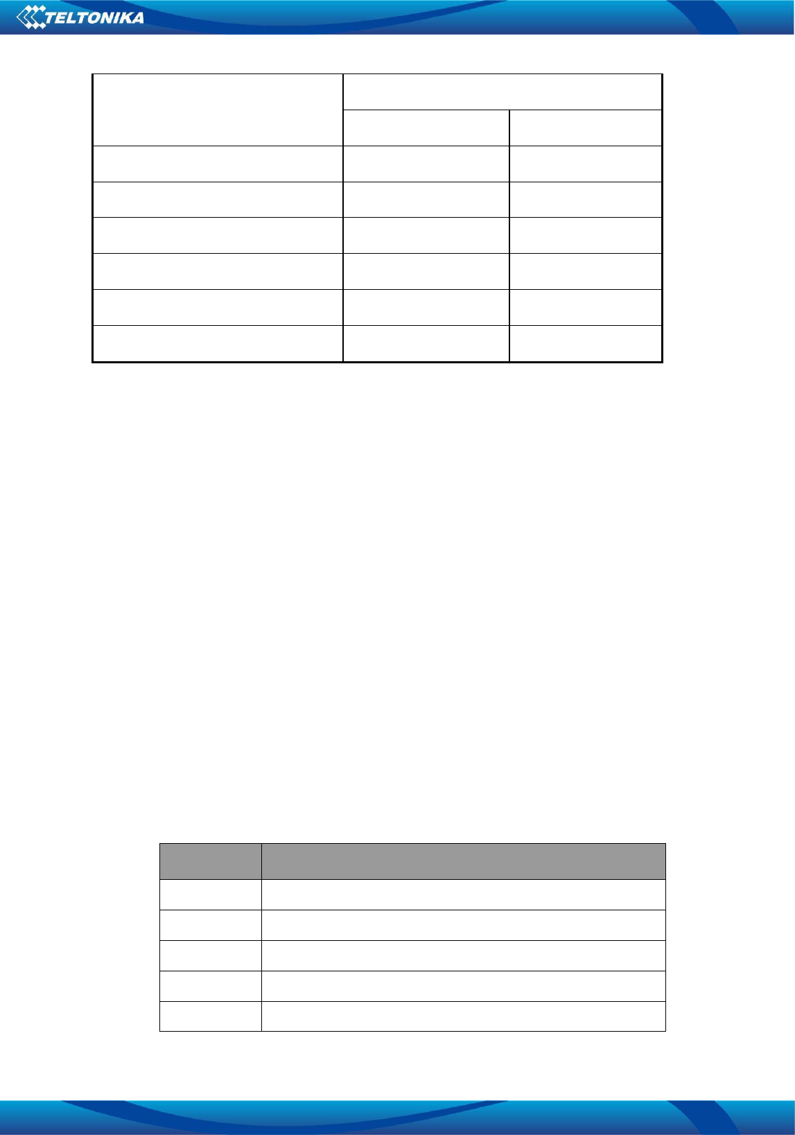
1.11 Powerconsumption
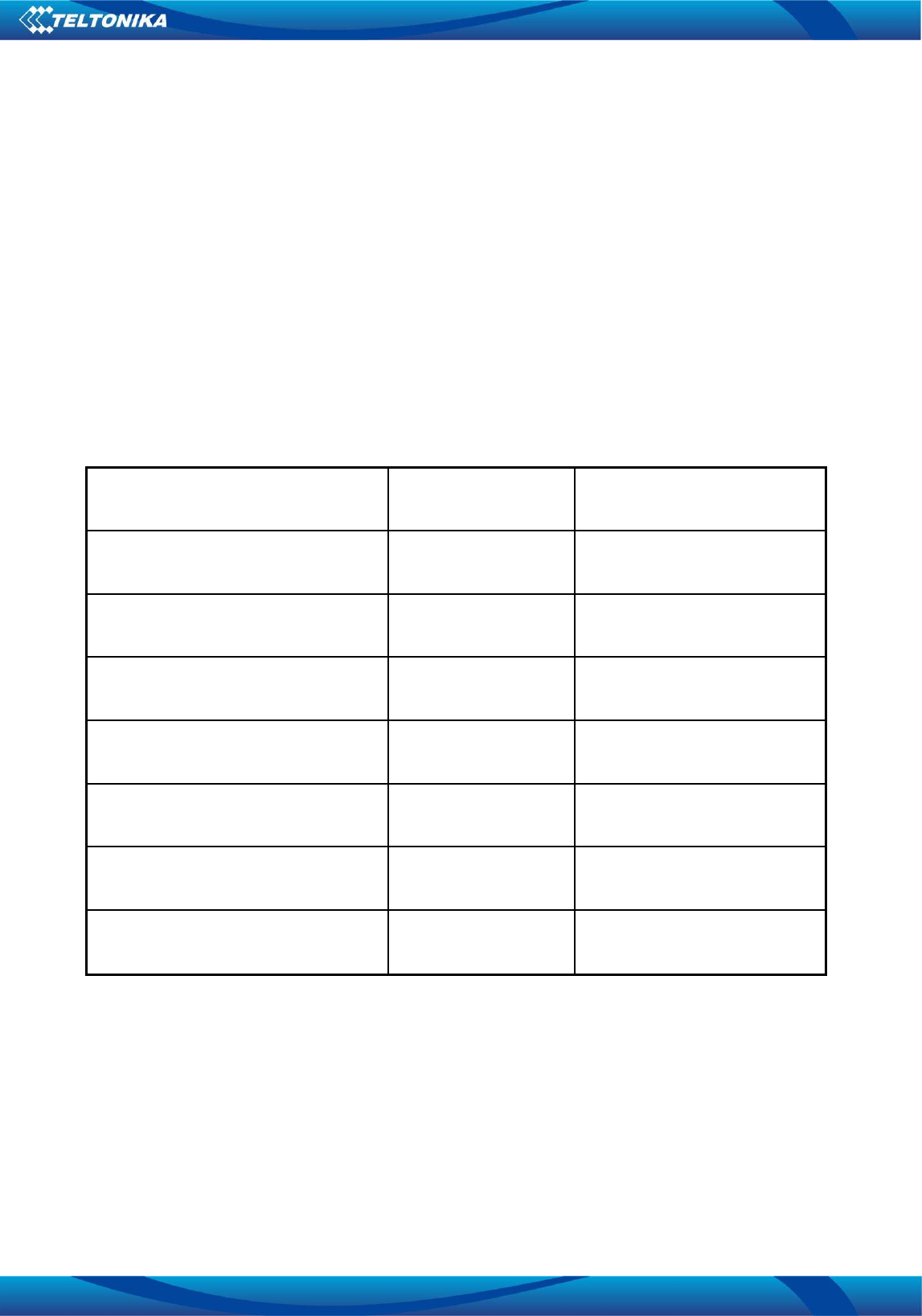
TM2500modulepowerconsumptions:
Table2Powerconsumptiontable
ModeAverageCurrent
ConsumptionNote
PowerOFFMode1.01mAModulesppliedbutSwitchedoff
2G(GSM)TalkMode@850/900MHz,
PCL=5(P=33dBm)251.7mA
2G(GSM)TalkMode@1800/1900
MHz,PCL=0(P=30dBm)181.5mA
2.5G(GPRS2+1)TBFmode@850/900
MHz,PCL=5(P=33dBm)252.7mA
2.5G(GPRS2+2)TBFmode@850/900
MHz,PCL=5(P=33dBm)365.5mA
2.5G(GPRS2+1)TBFmode
@1800/1900MHz,PCL=0(P=30dBm)175.5mA
2.5G(GPRS2+2)TBFmode
@1800/1900MHz,PCL=0(P=30dBm)256.2mA
Thelistedcurrentconsumptionvaluesarereferredtotheaveragecurrentconsumptionofthewhole
module,whenthemodulesupplyvoltageis4Vandsignalpoweris‐75dBm.
TheRFtransmissionisnotcontinuousintheGSMsystem,thetransmissionispackedintoburstsata
basefrequencyofabout216Hz,andtherelativecurrentpeakscanbeashighasabout2.5A.
Thereforethepowersupplyhastobedesignedinordertowithstandwiththesecurrentpeaks
withoutbigvoltagedrops.
Vilnius,
12/23
1.11.1 Powerdown
Thefollowingprocedurescanbeusedtoturnoffthemodule:
Normalpowerdownprocedure:TurnoffmoduleusingthePWRKEYpin.
Over‐voltageorunder‐voltageautomaticshutdown:Takeeffectwhenover‐voltageor
under‐voltageisdetected.
1.12 PowerSaving
Basedonsystemrequirements,thereareseveralactionstodrivethemoduletoenterlowcurrent
consumptionstatus.Forexample,„AT+CFUN“canbeusedtosetmoduleintominimumfunctionality
modeandDTRhardwareinterfacesignalcanbeusedtoleadsustemtoSLEEPmode.
1.13 Minimumfunctionalitymode
Minimumfunctionalitymodereducesthefunctionalityofthemoduletoaminimumlevel.The
consumptionofthecurrentcanbeminimizedwhentheslowclockingmodeisactivatedatthesame
time.Themodeissetwiththe“AT+CFUN”commandwhichprovidesthechoiceofthefunctionality
levels<AT+CFUN>=0,1,4.
0:minimalfunctionality,turnoffradioandSIMpower.
1:canenternormalmode,fullfunctionality.
4:canenterflightmode.
1.13.1 SLEEPmode
SLEEPmodeisdisabledbydefault.ItcanbeenabledbyAT+ESLP=1.ThedefaultsettingisAT+ESLP=0,
antinthismodeGSMparcannotenterSLEEPmode.
WhentheGSMpartissetbythecommandAT+QSCLK=1,youcancontroltheparttoenterintoor
exitfromtheSLEEPmodethroughpinDTR.WhenDTRissettohighlevel,andthereisnoon‐airor
hardwareinterruptsuchasGPIOinterruptordataonUARTport,theGSMpartwillenterintoSLEEP
modeautomatically.Inthismode,theGSMpartcanstillreceivevoice,SMSorGPRSpagingfrom
network,buttheUARTportdoesnotwork.
1.14 Bluetoothantennadescription
TM2500moduleprovidesaBluetoothantennapadnamedBT_ANT,pindefinitionlistedbelow.
Table3BT_ANTpindefinition
PinnamePinnumberDescription
BT_ANTA7BTantennapad
GNDA6,A8,B7Ground
Vilnius,
13/23
ItisnecessarytoaddadditionalBandPassfilterintothecircuit,werecommendMurataElectronics
filter,part.No:LFB182G45SG9A293.ForadditionalinformationpleaseseeTM2500_Blockdiagram
p.g10;
ForSMTBluetoothantennawerecommendtouseceramicantennaANT3216A063R2400A.
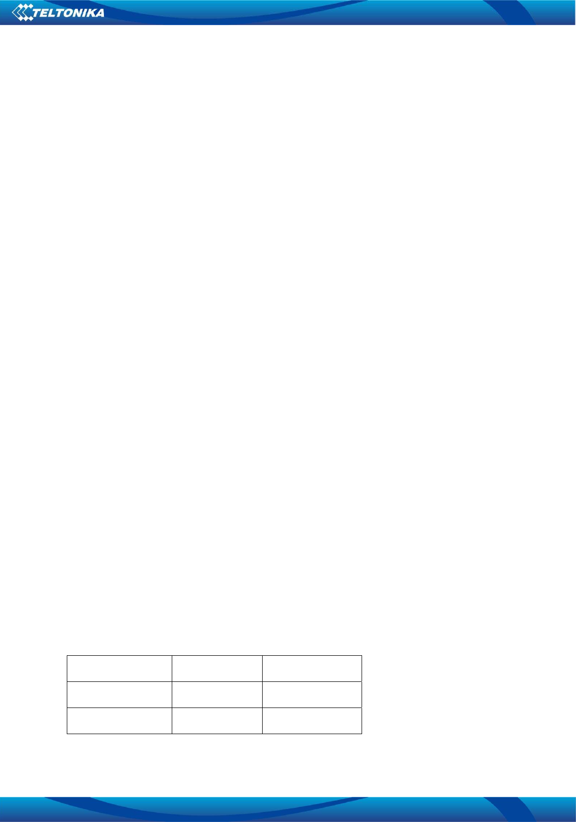
Table4Antennadescription
DescriptionValue
CenterFrequency2.45GHz
Bandwidth230MHz(Typ.)
ReturnLoos10dBmin
PolarizationLinear
AzimuthBeamwidthOmni‐directional
PeakGain≤1.69dBi(Typ.)
Impedance50Ω
OperatingTemperature‐40~105°C
MaximumPower1W
TerminationNi/Sn(Environmentally‐Friendly
Leadless)
ResistancetoSolderingHeats260°C,10sec.
OnourdevelopedEVBforTM2500,weusedcoplanarwaveguidetransmissionline.RFtransmission
linewidthis0.5mm,thicknessbetweentransmissionlineandgroundis0.125mm.Forexampleshow
tocalculateRFlineimpedanceseereferenceinTM2500technicaloperationdescriptions,p.g27‐29;
1.15 RFOutputPower
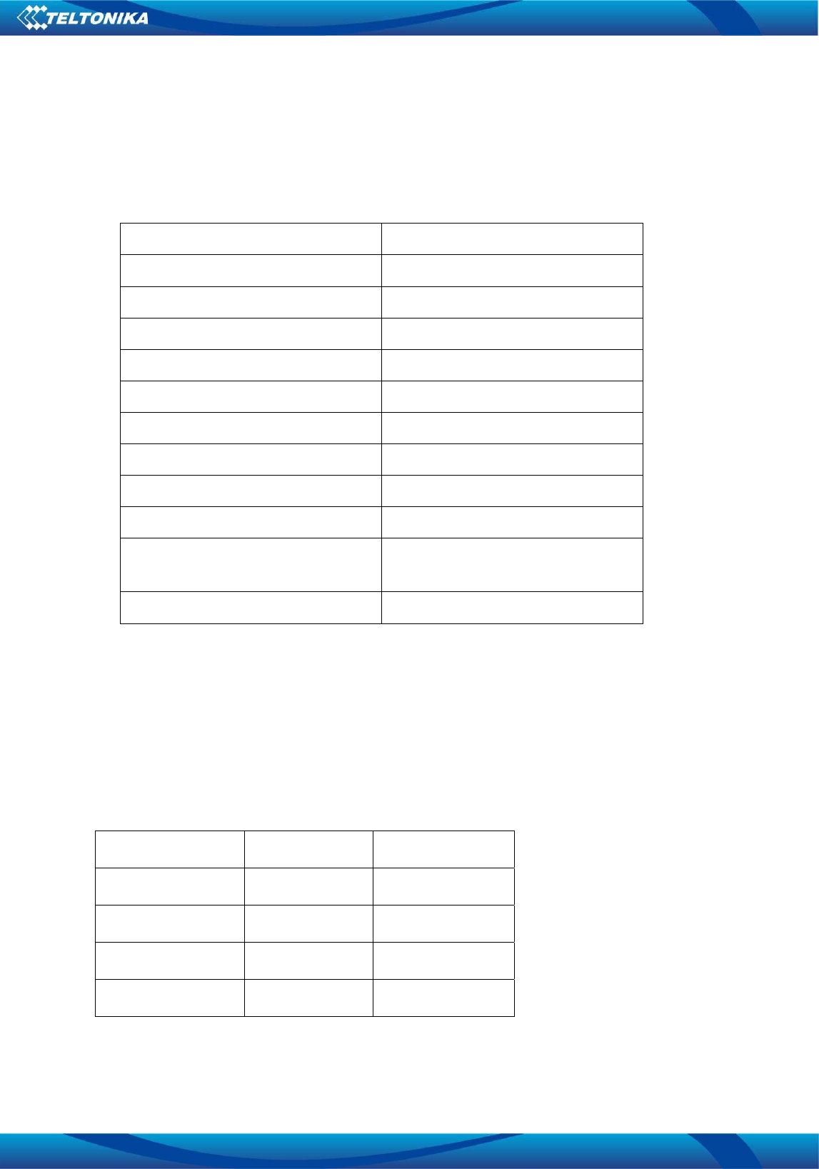
Table5RFOutputpower
FrequencyMax.Min.
GSM85033dBm5dBm±
EGSM90033dBm5dBm±
DCS180030dBm0dBm±
PCS190030dBm0dBm±
Vilnius,
14/23
1.16 RFReceivingSensitivity
Table6ReceivingSensitivity
FrequencyReceiveSensitivity
GSM850<‐110dBm
EGSM900<‐110dBm
DCS1800<‐110dBm
PCS1900<‐110dBm
1.17 OperatingFrequencies
Table7OperatingFrequencies
FrequenciesReceiveTransmitARFCH
GSM850869~894MHz824~849MHz128~251
EGSM900925~960MHz880~915MHz0~124,975~1023
DCS18001805~1880MHz1710~1785MHz512~885
PCS19001930~1990MHz1850~1910MHz512~810
DIGITALLEVELSPECIFICATIONS
ThefollowingtablesshowthedigitallevelsspecificationsusedintheTM25interfacecircuits:
1.18 DCcharacteristics
Absolutemaximumratings
Table8maximumratings
AbsoluteMaximumRating(NotFunctional):
Vilnius,
15/23
Description
Inputlevellimitvalues
MinMax
GenericdigitalinterfacesGPIO‐0.30V3.6V
I2Cinterface‐0.30V3.6V
UARTinterface‐0.30V3.6V
SIMinterface‐0.30V3.6V
PWR_ON‐0.30V3.6V
EXTRSTnsignal‐0.30V3.6V
CommunicatewithModule
0. ConnectthemainportofEVBorthemoduletoPC’sUSBportwiththeUSBtoUART
convertercable.
2.OpentheCOMPortTerminalonPC.SetappropriateBaudRate(suchas115200bps)and
COMPortnumberrelatedtomodule.
3.AttachGSM,GPSandifneededBLUETOOTHntenatoEVB.
4.InsertSIMcardintotheSIMcardsocket(mainsimcardsocketisclosertoPCB).
5.PowerONEVB.
6.Afterntenaf,inCOMPorttermianlwillappertext,withmeaningthatmoduleboot
started.Wait2‐3seconds,andmodulewillbereadyatacceptATcommands,ntenatoAT
commandsmanual.
Themoduleissettoautobaudingmodeindefaultconfiguration.Thisoperationisto
synchronizethebaudratebetweenthecomputerandthemodule.
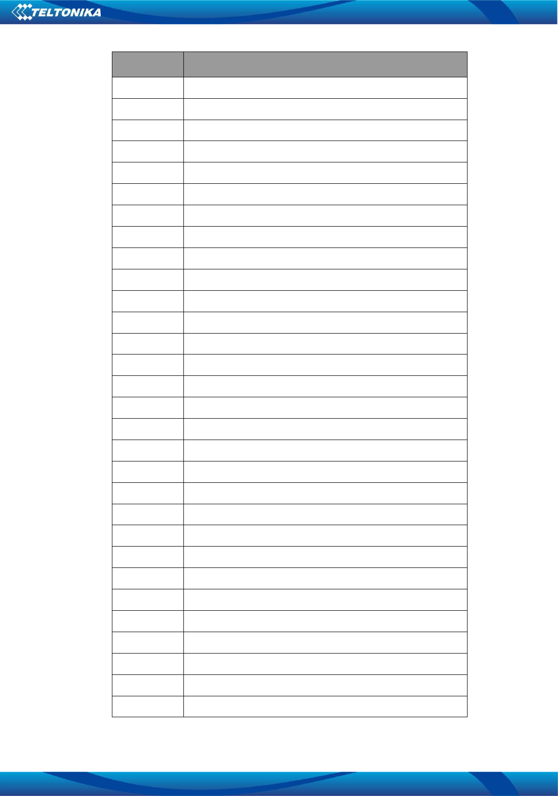
Table9TermsandAbbreviations
AbbreviationDescription
3GPP3rdGenerationPartnershipProject
8‐PSKEight‐PhaseShiftKeying
ACAlternatingCurrent
ADCAnalogtoDigitalConverter
AFCAutomaticFrequencyCorrection
Vilnius,
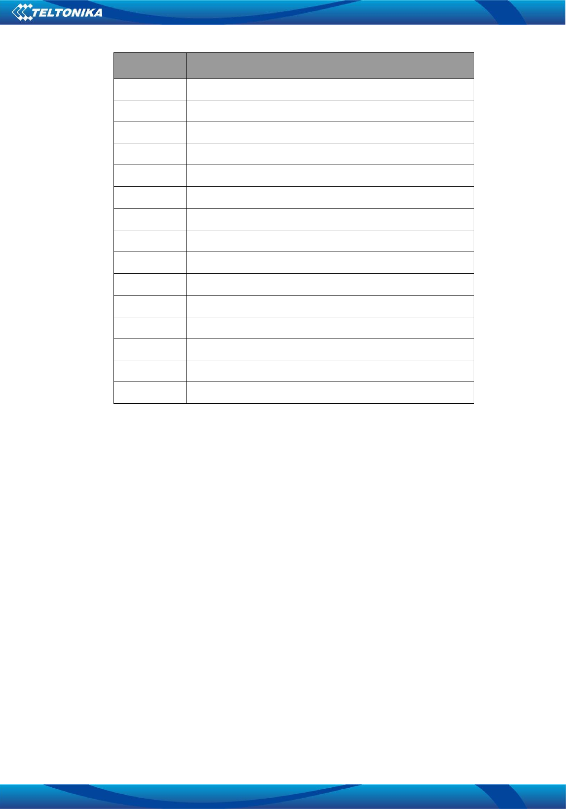
16/23
AbbreviationDescription
ASCAsynchronousSerialInterfaceController
ATATCommandInterpreterSoftwareSubsystem,orattention
B2BBoard‐to‐Board
BABTBritishApprovalsBoardforTelecommunications
CBCHCellBroadcastChannel
CBSCellBroadcastServices
CGUClockGenerationUnit
CSCodingSchemeorChipSelect
CSDCircuitSwitchedData
CTSClearToSend
DAIDigitalAudioInterface
DCDirectCurrent
DCDDatantenaDetect
DCEDataCommunicationEquipment
DCSDigitalCellularSystem
DLDownLink(Reception)
DSPDigitalSignalProcessing
DSRDataSetReady
DTEDataTerminalEquipment
DTMDualTransferMode
DTMFDualToneMultiFrequency
DTRDataTerminalReady
EDGEEnhancedDataratesforGSMEvolution
EEPROMElectricallyErasableandProgrammableROM
E‐GPRSEnhancedGPRS
EGSMExtendedGSM
EMCElectromagneticCompatibility
ESDElectrostaticDischarge
FDDFrequencyDivisionDuplex
FEMFrontEndModule

Vilnius,
17/23
AbbreviationDescription
FFSFlashFileSystem
GNDGround
GPIOGeneralPurposeInputOutput
GPRSGeneralPacketRadioService
GSMGlobalSystemforMobileCommunication
HDLCHighLevelDataLinkControl
HSDPAHighSpeedDownlinkPacketAccess
HWHardware
JTAGntenaTestActionGroup
I2CInter‐IntegratedCircuit
I2SInterICSound
IIRInfiniteImpulseResponse
IMEIInternationalMobileEquipmentIdentity
I/OInput/Output
IPInternetProtocol
IPCInterProcessorCommunication
ISOInternationalOrganizationforStandardization
ITUInternationalTelecommunicationUnion
LDOLow‐Dropout
LVDLowntenaDirective
M2MntenatoMachine
MCPMulti‐Chip‐Package
MCSModulationCodingScheme
MEMobileEquipment
MICTORMatchedntenafConnector
MIDIMusicalInstrumentDigitalInterface
MSMobileStation
MSCMobileSwitchingCentre
MUXMultiplexerorMultiplexed
NOMNetworkOperatingMode

Vilnius,
18/23
AbbreviationDescription
NTCntenafTemperatureCoefficient
PAPowerAmplifier
PBCCHPacketBroadcastControlChannel
PCPersonalComputer
PCBPrintedCircuitBoard
PCCCHPacketCommonControlChannel
PCSPersonalCommunicationsService
PDUProtocolDataUnit
PICSProtocolImplementationConformanceStatement
PIXITProtocolImplementationExtrantenafkonforTesting
PLMNPublicLandMobileNetwork
PMUPowerManagementUnit
PPSProtocolandntenafSelection
PSDPacketSwitchData
PSRAMPseudoStaticRandomAccessMemory
RFRadioFrequency
RIRingIndicator
ROMReadOnlyMemory
RTCRealTimeClock
RTSReadyToSend
RXReceiver
R&TTEDRadioandTeleTerminalEquipmentDirective
SAWSurfaceAcousticWave
SCCUStandbyClockControlUnit
SIMSubscriberIdentificationModule
SMASubMiniatureversionAconnector
SMPTESocietyofMotionPictureandTelevisionEngineers
SMSShortMessageService
SPISerialPeripheralInterface
SSCSynchronousSerialInterfaceController
Vilnius,
19/23
AbbreviationDescription
SWSoftware
TCHTrafficChannel
TCPTransmissionControlProtocol
TSTechnicalSpecification
TXTransmitter
UARTUniversalAsynchronousReceiver‐Transmitter
UDIUnrestrictedDigitalInformation
UEUserEquipment
UEAUMTSEncryptionAlgorithm
ULUpLink(Transmission)
UMTSUniversalMobileTelecommunicationsSystem
USBUniversalSerialBus
USIFUniversalSerialinterfaces
VC‐TCXOntenaControlled–TemperatureControlledCrystalOscillator
WCDMAWidebandCODEDivisionMultipleAccess
FCCRFEXPOSUREREQUIREMENTS
Standards and Regulatory Compliance
Standardsandcertification
The EUT conforms to the following standards and certification requirements:

Vilnius,
20/23
GSM850/1900, Bluetooth
FCC
❒ 47 CFR Part 1 – RF radiation exposure limits
❒ 47 CFR Part 2 – Equipment authorization
❒ 47 CFR Part C – Bluetooth
FCCcertificationrequirements.
According to the definition of mobile and fixed ntena is described in Part 2.1091(b), this
ntena is a mobile ntena.
And the following conditions must be met:
1. The EUT is a mobile ntena; maintain at least a 20 cm separation between the EUT and
the user’s body and must not transmit simultaneously with any other ntena or
transmitter.
2. The ntena is only for fixed operation mode. (A Class II Change would be required for
near-body Host applications.)
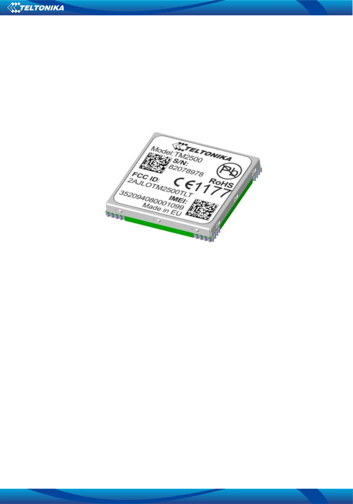
3. A label with the following statements must be attached to the host end product: This
ntena contains Tx FCC ID:2AJLOTM2500TLT
4. To comply with FCC regulations limiting both maximum RF output power and human
exposure to RF radiation, maximum ntena gain (including cable loss) must not exceed:
❒
GSM850/1900 band < 2 dBi
❒
Bluetooth <1.69 dBi
5. This module must not transmit simultaneously with any other ntena or
transmitter
6. The host end product must include a user manual that clearly defines operating
requirements and conditions that must be observed to ensure compliance with current
FCC RF exposure guidelines.

Vilnius,
21/23
For portable devices, in addition to the conditions 3 through 6 described above, a separate
approval is required to satisfy the SAR requirements of FCC Part 2.1093
If the device is used for other equipment that separate approval is required for all other
operating configurations, including portable configurations with respect to 2.1093 and
different antenna configurations.
For this device, OEM integrators must be provided with labeling instructions of finished
products. Please refer to KDB784748 D01 v07, section 8. Page 6/7 last two paragraphs:
A certified modular has the option to use a permanently affixed label, or an electronic
label. For a permanently affixed label, the module must be labelled with an FCC ID -
Section 2.926 (see 2.2 Certification (labelling requirements) above). The OEM manual
must provide clear instructions explaining to the OEM the labelling requirements, options
and OEM user manual instructions that are required (see next paragraph).
For a host using a certified modular with a standard fixed label, if (1) the module’s FCC
ID is not visible when installed in the host, or (2) if the host is marketed so that end users
do not have straightforward commonly used methods for access to remove the module so
that the FCC ID of the module is visible; then an additional permanent label referring to the
enclosed module:“ Contains Transmitter Module FCC ID:2AJLOTM2500TLT” or “Contains
FCC ID:2AJLOTM2500TLT” must be used. The host OEM user manual must also contain
clear instructions on how end users can find and/or access the module and the FCC ID.
The user manual or instruction manual for an intentional or unintentional radiator shall
caution the user that changes or modifications not expressly approved by the party
responsible for compliance could void the user's authority to operate the equipment. In
cases where the manual is provided only in a form other than paper, such as on a
computer disk or over the Internet, the information required by this section may be
included in the manual in that alternative form, provided the user can reasonably be
expected to have the capability to access information in that form.
This device complies with part 15 of the FCC Rules. Operation is subject to the following two
conditions: (1) This device may not cause harmful interference, and (2) this device must
accept any interference received, including interference that may cause undesired operation.
Caution: Changes or modifications not expressly approved by the manufacturer could void
the user’s authority to operate the equipment.

Vilnius,
22/23
This equipment has been tested and found to comply with the limits for a Class B digital
device, pursuant to part 15 of the FCC Rules. These limits are designed to provide
reasonable protection against harmful interference in a residential installation. This
equipment generates uses and can radiate radio frequency energy and, if not installed and
used in accordance with the instructions, may cause harmful interference to radio
communications. However, there is no guarantee that interference will not occur in a
particular installation. If this equipment does cause harmful interference to radio or
television reception, which can be determined by turning the equipment off and on, the user
is encouraged to try to correct the interference by one or more of the following measures:
- Reorient or relocate the receiving antenna.
- Increase the separation between the equipment and receiver.
-Connect the equipment into an outlet on a circuit different from that to which the receiver is
connected.
-Consult the dealer or an experienced radio/TV technician for help.
FCCRFexposurerequirements
1. Radiated transmit power must be equal to or lower than that specified in the FCC Grant of
Equipment Authorization for FCC ID:2AJLOTM2500TLT.
2. To comply with FCC regulations limiting both maximum RF output power and human
exposure to RF radiation, maximum antenna gain (including cable loss) must not exceed:
❒GSM850/1900 band <2 dBi
❒Bluetooth <1.69 dBi
3. This module must not transmit simultaneously with any other antenna or transmitter.
4. To ensure compliance with all non-transmitter functions the host manufacturer is
responsible for ensuring compliance with the module(s) installed and fully operational. For
example, if a host was previously authorized as an unintentional radiator under the
Declaration of Conformity procedure without a transmitter certified module and a module is
added, the host manufacturer is responsible for ensuring that the after the module is
installed and operational the host continues to be compliant with the Part 15B unintentional
radiator requirements.
Vilnius,
23/23
ChangeLog
Nr.DateVersionComments
12016‐08‐250.1Preliminarydraftrelease.
22016‐10‐240.2AddedBTantennainformationandreference.