UAT WL-3111 Wireless Access Point User Manual Manual 0806
UAT Inc. Wireless Access Point Manual 0806
UserManual.wiki
>
UAT
>
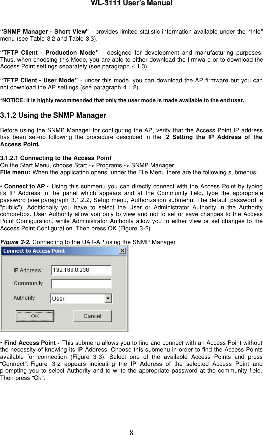
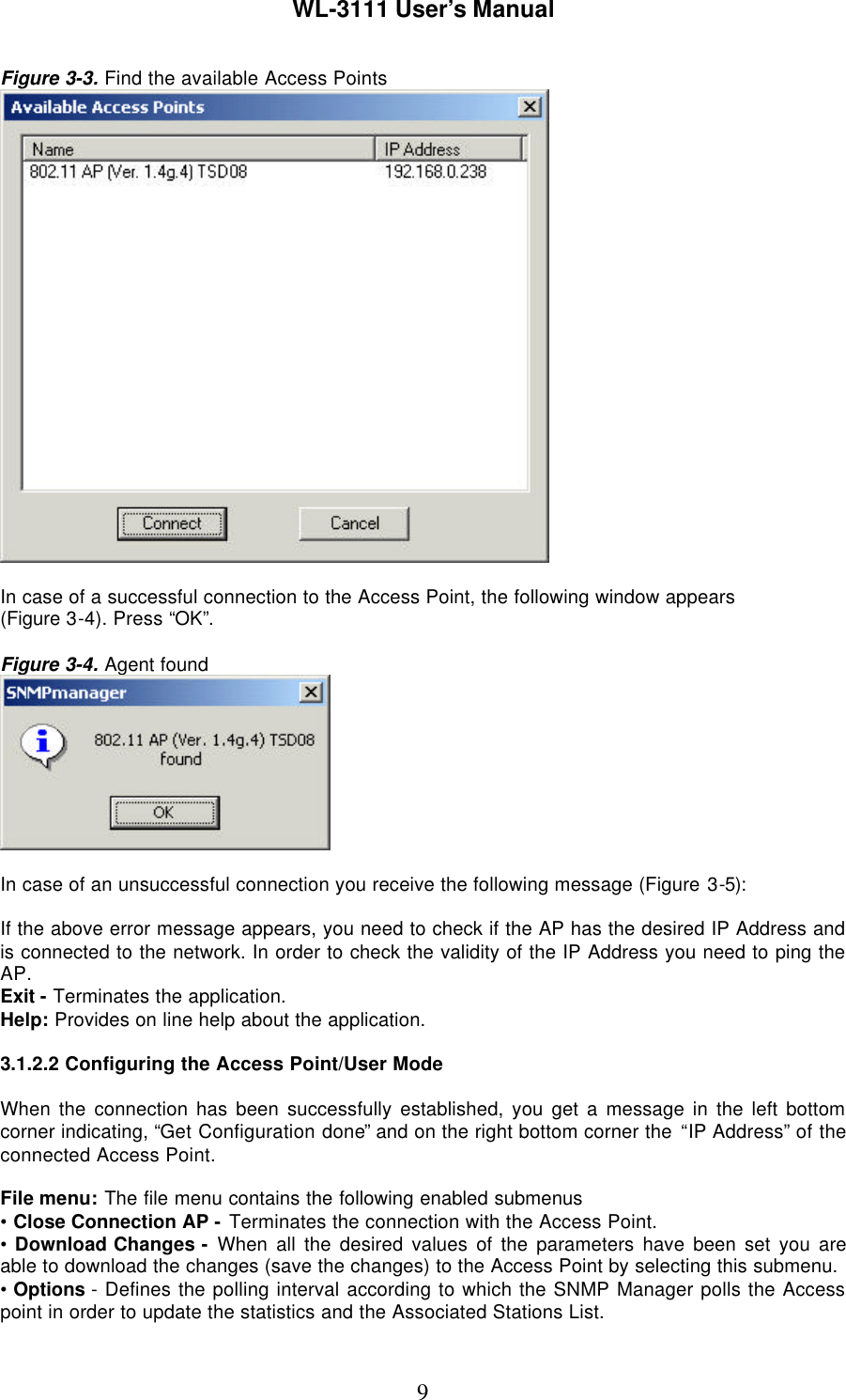
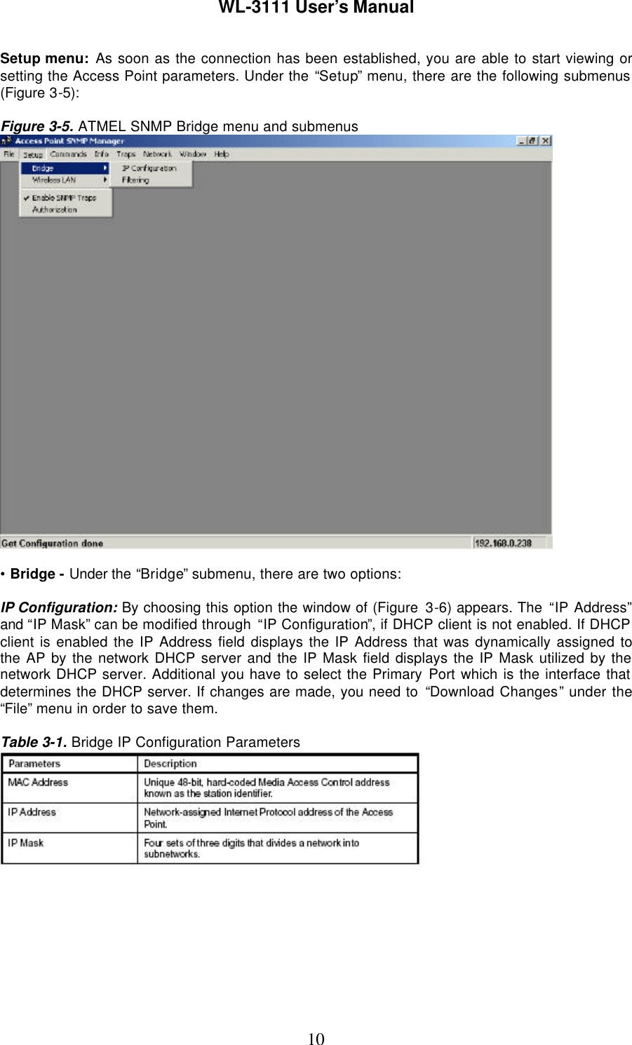
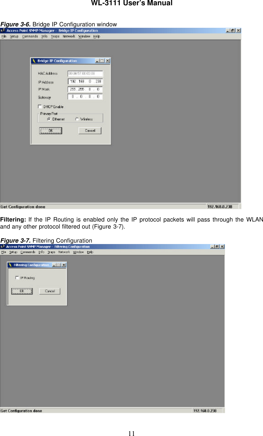
WL 3111 User Manual
Manual
Navigation menu
Upload a User Manual
Namespaces
Wiki Guide
HTML
PDF
Info
Views
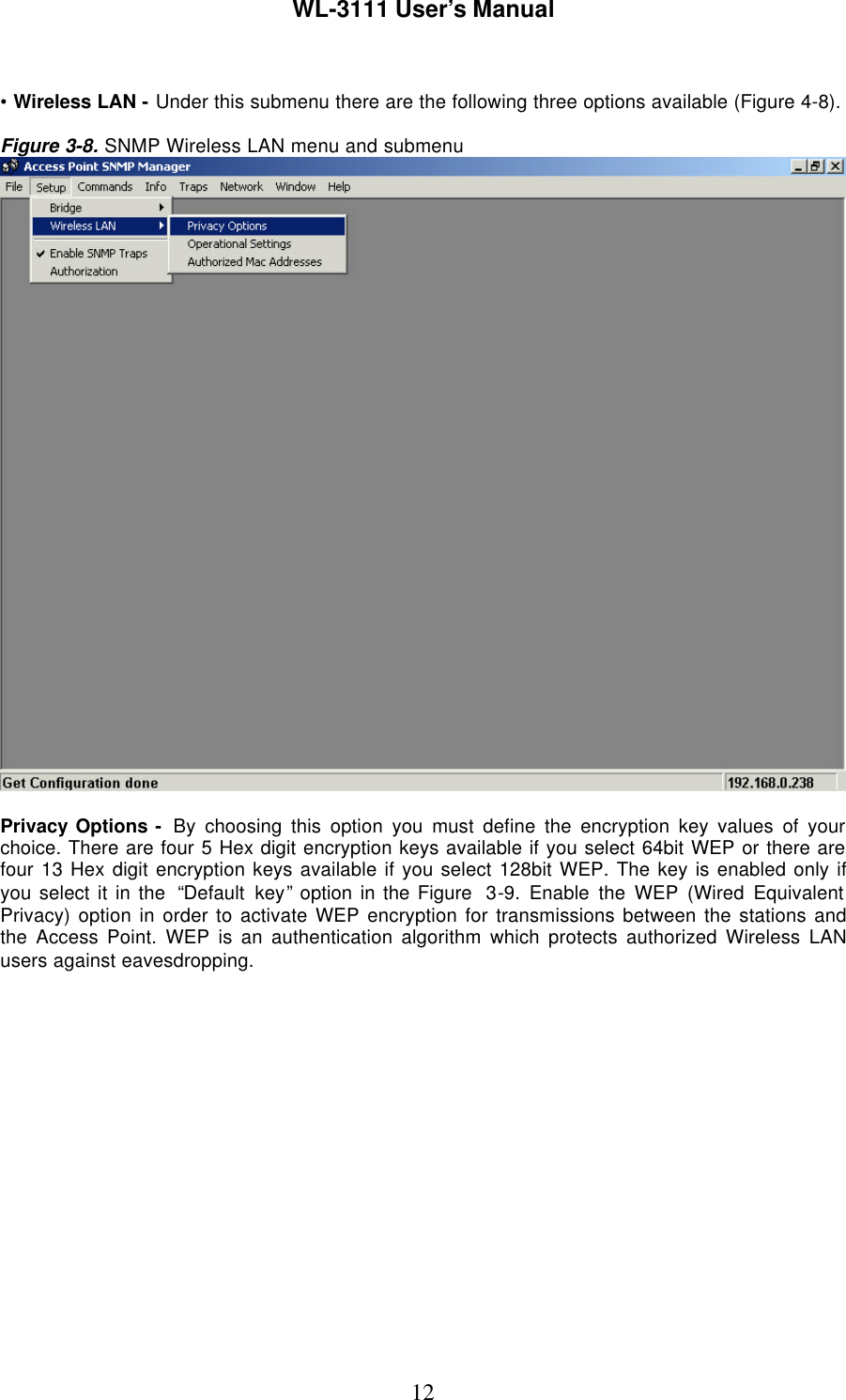
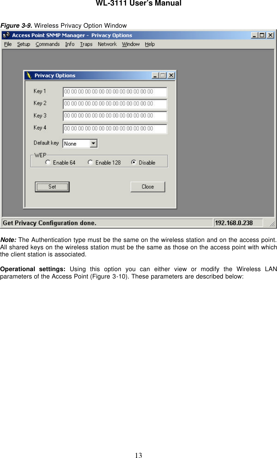
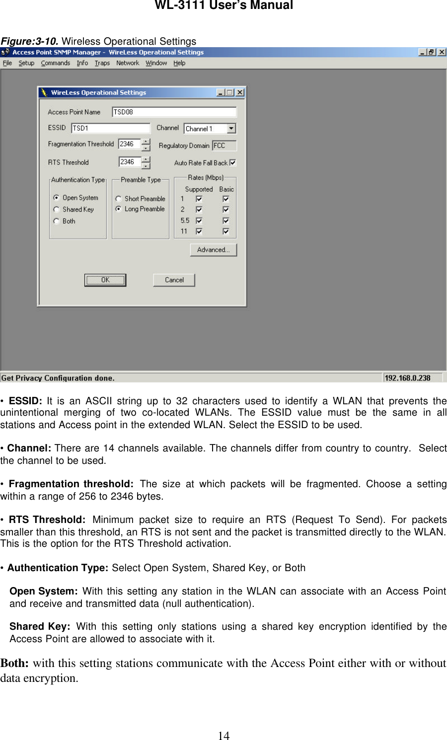
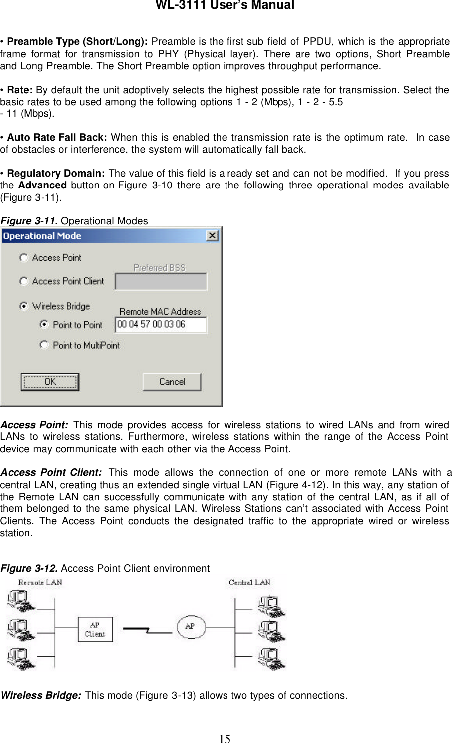
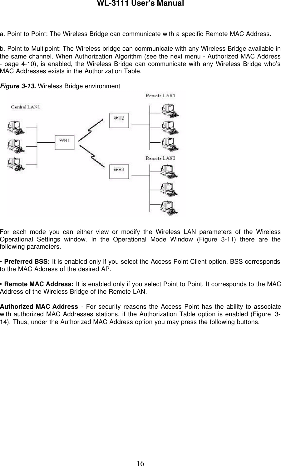
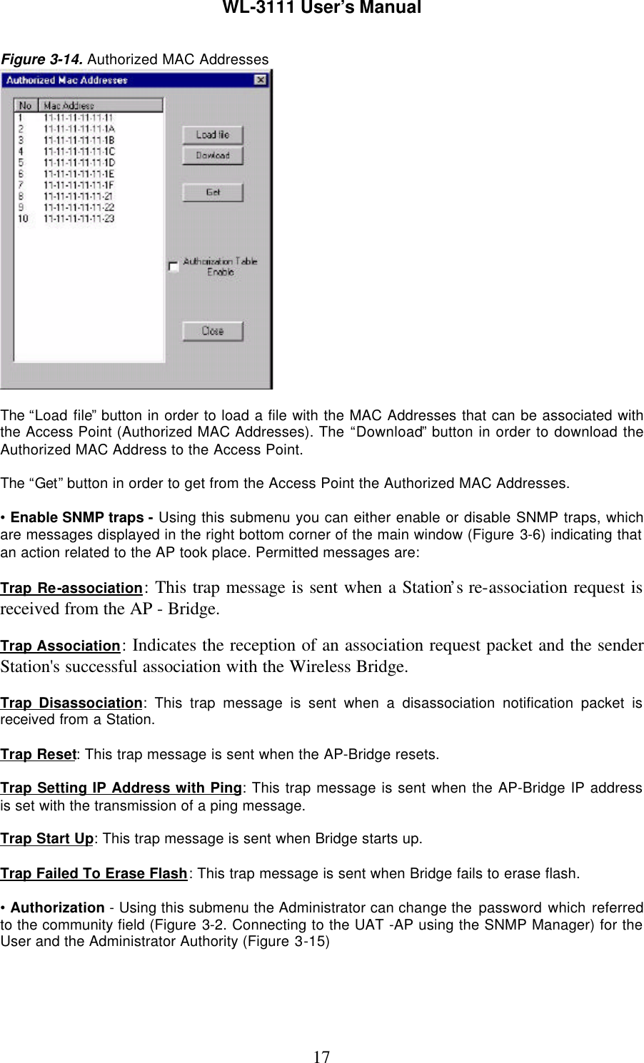
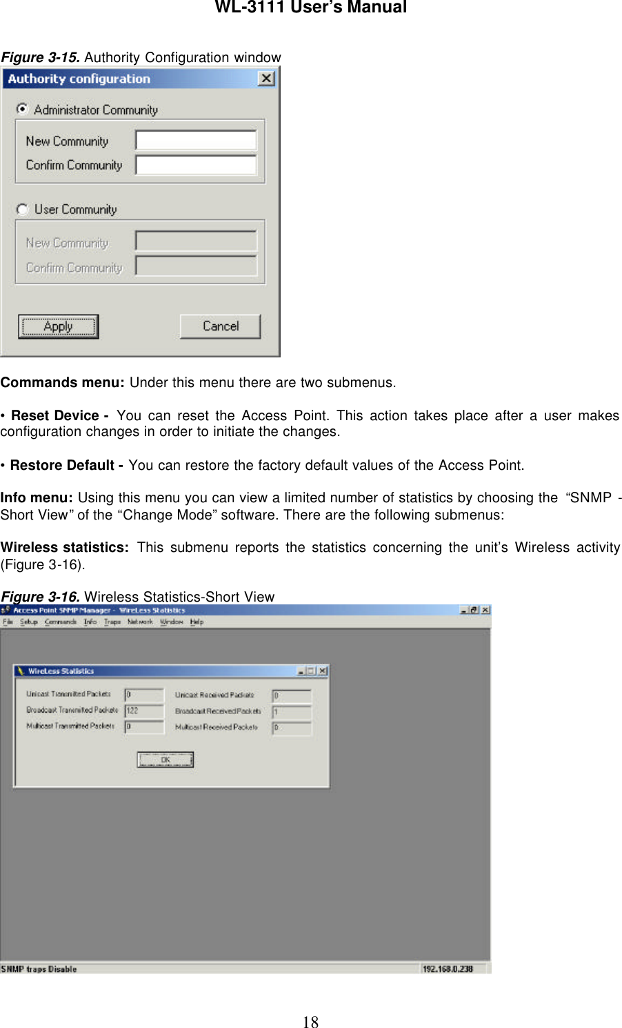
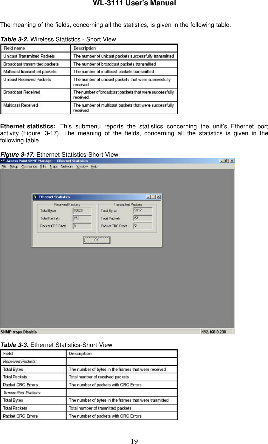
User Manual
Discussion / Help
Navigation