UAT WL-3111 Wireless Access Point User Manual Manual 0806
UAT Inc. Wireless Access Point Manual 0806
UAT >
Manual

Wireless Access Point
WL-3111
User’s Manual
This document contains confidential information and is proprietary to UAT Inc.
No part of this document may be reproduced in any form or by any means
without the prior permission of UAT Inc.
All specifications are subject to change without notice.
UAT Inc.
2F, No.5, Alley22, Lane 513, Jui Kuang Rd,
Nei Hu, Taipei, Taiwan, R.O.C
Tel: (886) 2 8797 8488
Fax: (886) 2 2657 0997

WL-3111 User’s Manual
1
Copyright
Copyright © 2001, All rights reserved.
This manual and software described in it are copyrighted with all rights reserved. This manual may not be
copied, in whole or in part, without written consent. All product names are trademarks and or registered
trademarks of their respective companies.
WL-3111 User’s Manual
2
Table of Contents
1 Introduction
1.1 Package Contents………………………………………… 3
1.2 System Requirements…………………………………….4
1.3 Applications………………………………………………… 4
1.4 Features & Benefits…………………………………….….4
2 Setting the IP Address of AP
2.1 sing the Ethernet Port/Wireless Port……………………… 5
2.1.1 Using ARP/Ping commands…………………………………… 5
2.1.2 DHCP client……………………………………………………… 6
3 Access Point Configuration
3.1 Using the Ethernet Port/Wireless Port. ………………….7
3.1.1 How to Install the SNMP Manager…………………………….7
3.1.1.1 ChangeMode………………………………………………………… 7
3.1.2 Using the SNMP Manager. …………………………………… 8
3.1.2.1 Connecting to the Access Point ………………………………….. 8
3.1.2.2 Configuring the Access Point/User Mode ……………………….. 9
4 Access Point Firmware Upgrade
4.1 Using the Ethernet Port/Wireless Port…………………… 21
4.1.1 How to Install TFTP Client……………………………………... 21
4.1.2 Using the TFTP Client/User Mode…………………………….21
4.1.3 Using the TFTP Client/Production Mode………………………22
4.1.4 How to Uninstall TFTP Client………………………………….. 22
FCC Regulation……………………………………………………..23
WL-3111 User’s Manual
3
1. Introduction
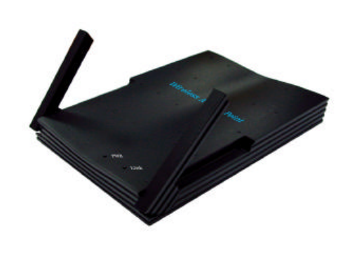
The WL-3111 AP is a 11Mbps high-speed Access Point for wireless connectivity interoperable
with IEEE 802.11b, 2.4GHz Direct Sequence Spread Spectrum (DSSS) compliant equipment.
The figure 1-1 shows WL-3111 AP outline
Figure 1-1
1.1 Package Contents
Please make sure that you received the following with your WL-3111 Access Point.
• One Access Point
• One Ethernet Cable
• One Power Adapter
• One User Guide
• One Installation CD
WL-3111 User’s Manual
4
1.2 System Requirements
Installation of the Access Point requires:
• An A/C power adapter which supplies the power for the Access Point.
• A 10Base-T Ethernet cable (RJ-45 connector)
• A window-based PC/AT compatible computer
1.3 Applications
The WL-3111 AP is easy to install and highly efficient. The following list is to describe
many applications can be done through Access Point and related device such as PCMCIA
card for Notebook, USB adapter for desktop PC.
– Small Office and Home Office (SOHO) networks
– Exhibition Centers/Fairs
– Temporary Workgroups
– Hard-to-Wire Buildings
– Wireless Extensions to Wired Networks
– Construction Sites
– Training/Educational Facilities
1.4 Features & Benefits
– High-speed 11Mbps data transmission.
– Fully interoperable with IEEE 802.11b compliant products
– WEP data encryption/decryption
– DHCP client simplifies network administration
– Read-Write access for the Hardware Configuration through the SNMP Manager
– Web/Telnet/SNMP Management helps administrators to remotely configure or manage the
Access Point with a Web Browser, Telnet or SNMP Protocol
– Seamless Roaming Capability allows users to move to anywhere without losing network
connection
WL-3111 User’s Manual
5
2. Setting the IP Address of the AP
The first step in using the WL-3111 AP is to set its IP Address. This procedure can be done
through the Ethernet/Wireless port by using a combination of ARP/Ping commands and the
SNMP Manager, or by the network DHCP server.
2.1 Using the Ethernet Port/Wireless Port
You can set the Access Point IP Address using the ARP/ping commands or by the network
DHCP server.
2.1.1 Using ARP/Ping commands
In order to set the Access Point IP address you need to know the Access Point MAC address.
Follow the steps below giving the Access Point a temporary address at the beginning (Step A)
and saving the IP address through the SNMP Manager application (Step B).
Step A:
1. Connect an Ethernet station and the Access Point on the same subnet. The simplest way to
accomplish that is to connect the Access Point and the Ethernet station to the same hub. You
need to check if the station IP address and the Subnet mask are configured properly. Also the
new IP address for the Access Point must correspond to the Subnet mask.
2. Open an MS-DOS Prompt window and enter a static route in the ARP table for the new IP
address you want to assign. Use the ARP -s command to do that:
ARP -s "new-IP-address" "AP-MAC-address" (The MAC-address of the Access Point is indicated
in the back of the Access Point board.
For example: ARP-s 10.170.254.27 00-04-25-02-00-10
3. Ping the Access Point, using its new IP address.
For example: ping 10.170.254.27
If you get a ping reply, then the IP address has been temporarily set. In order to set it
permanently you need to proceed to Step B without powering off the Access Point.
Step B:
1. Open the SNMP Manager application. In order to install the SNMP Manager application,
please refer to paragraph 3.1.1 “How to Install the SNMP Manager”.
2. Connect to the access point by selecting the “Connect AP” submenu under the “File” menu.
Type the IP address of the access point (which has been temporarily set in Step A) in the panel
which appears, type “public” at the Community field, select “Administrator” in the Authority
combo-box and then press OK. The SNMP Manager will inform you that the access point has
been found and that all the configuration values have been retrieved.
WL-3111 User’s Manual
6
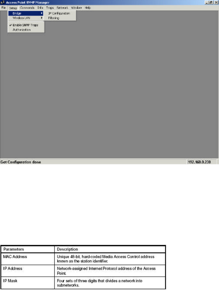
3. Under the “Setup” -> “Bridge” submenu, select “IP Configuration”. Type the IP Address of Step
A in the configuration window that appears. Confirm the validity of the other values (MAC Address
and IP Mask), and select the Primary Port which determines the Access Point’s MAC Address
and IP Address and press “OK”.
4. Save the configuration by selecting “Download Changes” under the “File” menu. The IP
address of the access point has now been set permanently.
2.1.2 DHCP client
1. If DHCP client is enabled the IP Address field displays the IP Address that was dynamically
assigned to the Access Point by the network DHCP server. The IP Mask field displays the IP
Mask utilized by the network DHCP server. Select the Primary Port which is the interface that
determines the DHCP server and press “OK”. If the network server failed to give an IP Address to
the Access Point, then the Access Point IP Address is the default one.
See also the paragraph 3.1.2 “Using the SNMP Manager”.
WL-3111 User’s Manual
7
3. Access Point Configuration
The WL-3111 AP configuration can be done either through the Ethernet/Wireless port by using
the SNMP Manager application.
3.1 Using the Ethernet Port/Wireless Port
In order to configure the AP through the Ethernet Port/Wireless Port, you must first install the
SNMP Manager application, which is a powerful and reliable tool used for the remote
configuration of the Access Point through the Ethernet Port/Wireless Port.
3.1.1 How to Install the SNMP Manager
In order to install the SNMP Manager you need to run the program “Setup.exe” which you will find
into the “SNMP” sub-folder of the “Utilities” folder in your CD. Follow the instructions of the set-up
program and select the directory where the application will be installed. Finally, a window appears
indicating the completion of the installation.
3.1.1.1 ChangeMode
This software tool has been designed to provide the customers with different modes of use,
concerning the SNMP Manager application or TFTP Client application according to the
customer’s attribute. In order to use this application, run the ChangeMode.exe and follow the
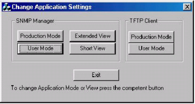
instructions. The following window appears (Figure 3-1).
Figure 3-1. The Change Application Settings
Under this window the following options are available:
“SNMP Manager - Production Mode” - designed for development and manufacturing purposes.
Thus, when choosing this Mode, an additional menu “Radio” is available for testing the Access
Point. Under the “Setup” menu there is also an additional submenu available “Hardware” which
provides the possibility to either view or modify the Hardware Configuration. The additional
menus available when choosing this Mode are described in paragraph 3.1.2.3. “Configuring
Access Point/Production Mode”.
“SNMP Manager - User Mode” - the above mentioned “Radio” menu and “Hardware” submenu
aren’t available in this Mode. The Configuring Menus available when choosing this mode are
described in paragraph 3.1.2.2 “Configuring the Access Point/User Mode”.
“SNMP Manager - Extended View” - provides extended statistic information available under the
“Info” menu (see Table 3.4 and Table 3.5)
WL-3111 User’s Manual
8
“SNMP Manager - Short View” - provides limited statistic information available under the “Info”
menu (see Table 3.2 and Table 3.3).
“TFTP Client - Production Mode” - designed for development and manufacturing purposes.
Thus, when choosing this Mode, you are able to either download the firmware or to download the
Access Point settings separately (see paragraph 4.1.3).
“TFTP Client - User Mode” - under this mode, you can download the AP firmware but you can
not download the AP settings (see paragraph 4.1.2).
*NOTICE: It is highly recommended that only the user mode is made available to the end user.
3.1.2 Using the SNMP Manager
Before using the SNMP Manager for configuring the AP, verify that the Access Point IP address
has been set-up following the procedure described in the 2 Setting the IP Address of the
Access Point.
3.1.2.1 Connecting to the Access Point
On the Start Menu, choose Start -> Programs -> SNMP Manager.
File menu: When the application opens, under the File Menu there are the following submenus:
• Connect to AP - Using this submenu you can directly connect with the Access Point by typing
its IP Address in the panel which appears and at the Community field, type the appropriate
password (see paragraph 3.1.2.2, Setup menu, Authorization submenu. The default password is
"public"). Additionally you have to select the User or Administrator Authority in the Authority
combo-box. User Authority allow you only to view and not to set or save changes to the Access
Point Configuration, while Administrator Authority allow you to either view or set changes to the
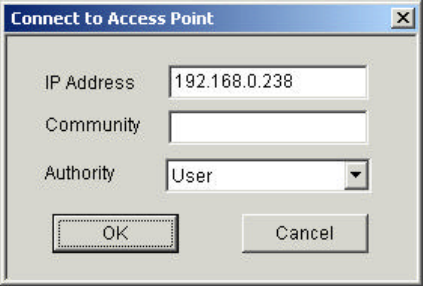
Access Point Configuration. Then press OK (Figure 3-2).
Figure 3-2. Connecting to the UAT-AP using the SNMP Manager
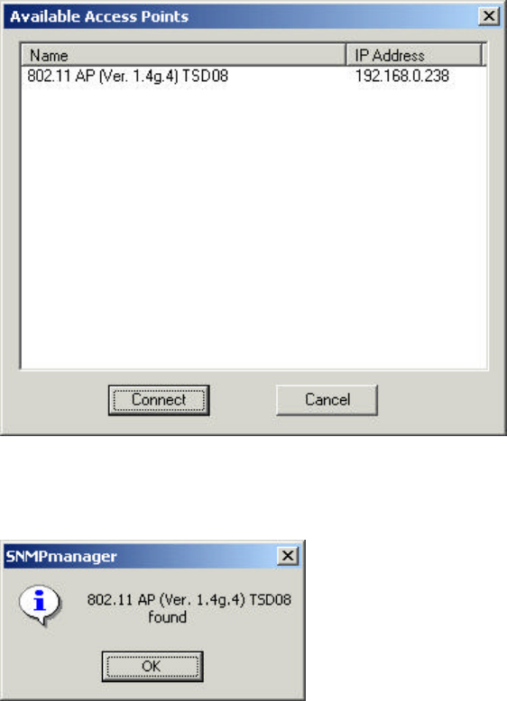
• Find Access Point - This submenu allows you to find and connect with an Access Point without
the necessity of knowing its IP Address. Choose this submenu in order to find the Access Points
available for connection (Figure 3-3). Select one of the available Access Points and press
“Connect”. Figure 3-2 appears indicating the IP Address of the selected Access Point and
prompting you to select Authority and to write the appropriate password at the community field.
Then press “Ok”.
WL-3111 User’s Manual
9
Figure 3-3. Find the available Access Points
In case of a successful connection to the Access Point, the following window appears
(Figure 3-4). Press “OK”.
Figure 3-4. Agent found
In case of an unsuccessful connection you receive the following message (Figure 3-5):
If the above error message appears, you need to check if the AP has the desired IP Address and
is connected to the network. In order to check the validity of the IP Address you need to ping the
AP.
Exit - Terminates the application.
Help: Provides on line help about the application.
3.1.2.2 Configuring the Access Point/User Mode
When the connection has been successfully established, you get a message in the left bottom
corner indicating, “Get Configuration done” and on the right bottom corner the “IP Address” of the
connected Access Point.
File menu: The file menu contains the following enabled submenus
• Close Connection AP - Terminates the connection with the Access Point.
• Download Changes - When all the desired values of the parameters have been set you are
able to download the changes (save the changes) to the Access Point by selecting this submenu.
• Options - Defines the polling interval according to which the SNMP Manager polls the Access
point in order to update the statistics and the Associated Stations List.
WL-3111 User’s Manual
10
Setup menu: As soon as the connection has been established, you are able to start viewing or
setting the Access Point parameters. Under the “Setup” menu, there are the following submenus
(Figure 3-5):
Figure 3-5. ATMEL SNMP Bridge menu and submenus
• Bridge - Under the “Bridge” submenu, there are two options:
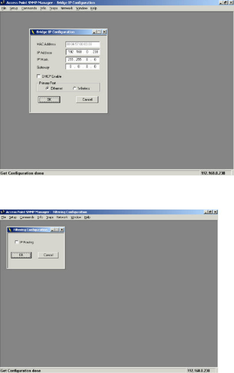
IP Configuration: By choosing this option the window of (Figure 3-6) appears. The “IP Address”
and “IP Mask” can be modified through “IP Configuration”, if DHCP client is not enabled. If DHCP
client is enabled the IP Address field displays the IP Address that was dynamically assigned to
the AP by the network DHCP server and the IP Mask field displays the IP Mask utilized by the
network DHCP server. Additional you have to select the Primary Port which is the interface that
determines the DHCP server. If changes are made, you need to “Download Changes” under the
“File” menu in order to save them.
Table 3-1. Bridge IP Configuration Parameters
WL-3111 User’s Manual
11
Figure 3-6. Bridge IP Configuration window
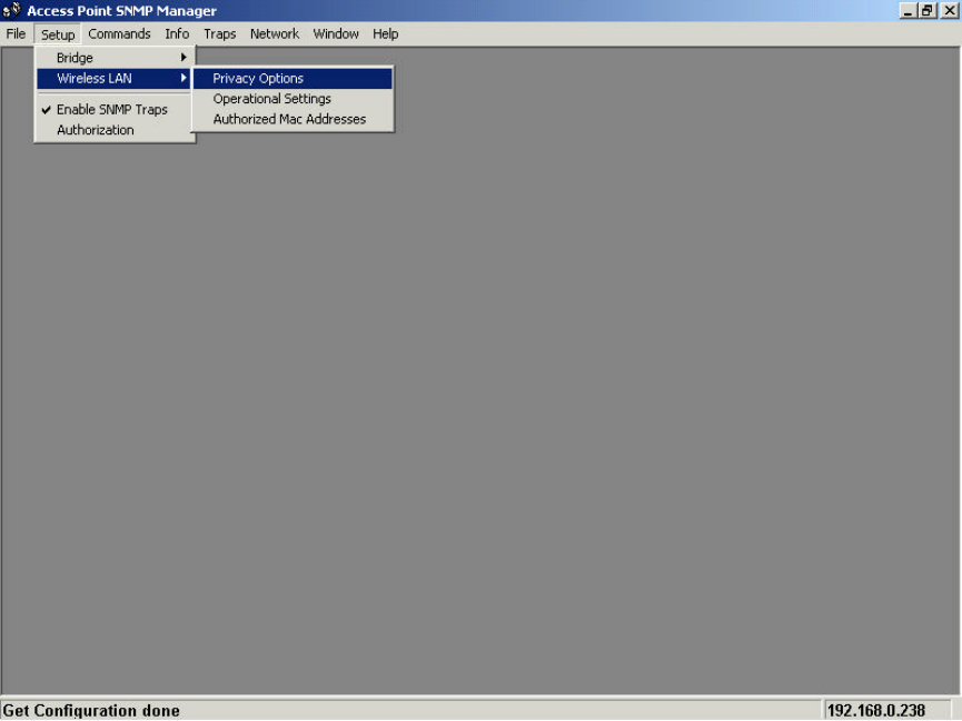
Filtering: If the IP Routing is enabled only the IP protocol packets will pass through the WLAN
and any other protocol filtered out (Figure 3-7).
Figure 3-7. Filtering Configuration
WL-3111 User’s Manual
12
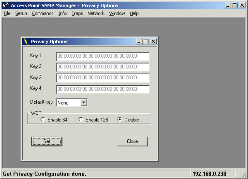
• Wireless LAN - Under this submenu there are the following three options available (Figure 4-8).
Figure 3-8. SNMP Wireless LAN menu and submenu
Privacy Options - By choosing this option you must define the encryption key values of your
choice. There are four 5 Hex digit encryption keys available if you select 64bit WEP or there are
four 13 Hex digit encryption keys available if you select 128bit WEP. The key is enabled only if
you select it in the “Default key” option in the Figure 3-9. Enable the WEP (Wired Equivalent
Privacy) option in order to activate WEP encryption for transmissions between the stations and
the Access Point. WEP is an authentication algorithm which protects authorized Wireless LAN
users against eavesdropping.
WL-3111 User’s Manual
13
Figure 3-9. Wireless Privacy Option Window
Note: The Authentication type must be the same on the wireless station and on the access point.
All shared keys on the wireless station must be the same as those on the access point with which
the client station is associated.
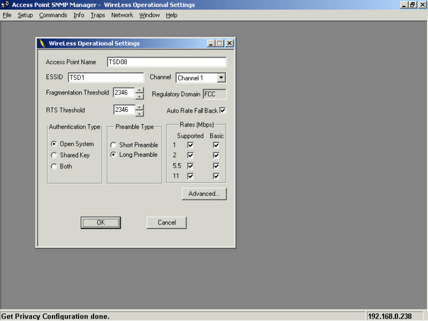
Operational settings: Using this option you can either view or modify the Wireless LAN
parameters of the Access Point (Figure 3-10). These parameters are described below:
WL-3111 User’s Manual
14
Figure:3-10. Wireless Operational Settings
• ESSID: It is an ASCII string up to 32 characters used to identify a WLAN that prevents the
unintentional merging of two co-located WLANs. The ESSID value must be the same in all
stations and Access point in the extended WLAN. Select the ESSID to be used.
• Channel: There are 14 channels available. The channels differ from country to country. Select
the channel to be used.
• Fragmentation threshold: The size at which packets will be fragmented. Choose a setting
within a range of 256 to 2346 bytes.
• RTS Threshold: Minimum packet size to require an RTS (Request To Send). For packets
smaller than this threshold, an RTS is not sent and the packet is transmitted directly to the WLAN.
This is the option for the RTS Threshold activation.
• Authentication Type: Select Open System, Shared Key, or Both
Open System: With this setting any station in the WLAN can associate with an Access Point
and receive and transmitted data (null authentication).
Shared Key: With this setting only stations using a shared key encryption identified by the
Access Point are allowed to associate with it.
Both: with this setting stations communicate with the Access Point either with or without
data encryption.
WL-3111 User’s Manual
15
• Preamble Type (Short/Long): Preamble is the first sub field of PPDU, which is the appropriate
frame format for transmission to PHY (Physical layer). There are two options, Short Preamble
and Long Preamble. The Short Preamble option improves throughput performance.
• Rate: By default the unit adoptively selects the highest possible rate for transmission. Select the
basic rates to be used among the following options 1 - 2 (Mbps), 1 - 2 - 5.5
- 11 (Mbps).
• Auto Rate Fall Back: When this is enabled the transmission rate is the optimum rate. In case
of obstacles or interference, the system will automatically fall back.
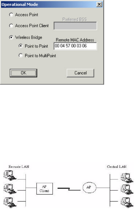
• Regulatory Domain: The value of this field is already set and can not be modified. If you press
the Advanced button on Figure 3-10 there are the following three operational modes available
(Figure 3-11).
Figure 3-11. Operational Modes
Access Point: This mode provides access for wireless stations to wired LANs and from wired
LANs to wireless stations. Furthermore, wireless stations within the range of the Access Point
device may communicate with each other via the Access Point.
Access Point Client: This mode allows the connection of one or more remote LANs with a
central LAN, creating thus an extended single virtual LAN (Figure 4-12). In this way, any station of
the Remote LAN can successfully communicate with any station of the central LAN, as if all of
them belonged to the same physical LAN. Wireless Stations can’t associated with Access Point
Clients. The Access Point conducts the designated traffic to the appropriate wired or wireless
station.
Figure 3-12. Access Point Client environment
Wireless Bridge: This mode (Figure 3-13) allows two types of connections.
WL-3111 User’s Manual
16
a. Point to Point: The Wireless Bridge can communicate with a specific Remote MAC Address.
b. Point to Multipoint: The Wireless bridge can communicate with any Wireless Bridge available in
the same channel. When Authorization Algorithm (see the next menu - Authorized MAC Address
- page 4-10), is enabled, the Wireless Bridge can communicate with any Wireless Bridge who’s
MAC Addresses exists in the Authorization Table.
Figure 3-13. Wireless Bridge environment
For each mode you can either view or modify the Wireless LAN parameters of the Wireless
Operational Settings window. In the Operational Mode Window (Figure 3-11) there are the
following parameters.
• Preferred BSS: It is enabled only if you select the Access Point Client option. BSS corresponds
to the MAC Address of the desired AP.
• Remote MAC Address: It is enabled only if you select Point to Point. It corresponds to the MAC
Address of the Wireless Bridge of the Remote LAN.
Authorized MAC Address - For security reasons the Access Point has the ability to associate
with authorized MAC Addresses stations, if the Authorization Table option is enabled (Figure 3-
14). Thus, under the Authorized MAC Address option you may press the following buttons.

WL-3111 User’s Manual
17
Figure 3-14. Authorized MAC Addresses
The “Load file” button in order to load a file with the MAC Addresses that can be associated with
the Access Point (Authorized MAC Addresses). The “Download” button in order to download the
Authorized MAC Address to the Access Point.
The “Get” button in order to get from the Access Point the Authorized MAC Addresses.
• Enable SNMP traps - Using this submenu you can either enable or disable SNMP traps, which
are messages displayed in the right bottom corner of the main window (Figure 3-6) indicating that
an action related to the AP took place. Permitted messages are:
Trap Re-association: This trap message is sent when a Station’s re-association request is
received from the AP - Bridge.
Trap Association: Indicates the reception of an association request packet and the sender
Station's successful association with the Wireless Bridge.
Trap Disassociation: This trap message is sent when a disassociation notification packet is
received from a Station.
Trap Reset: This trap message is sent when the AP-Bridge resets.
Trap Setting IP Address with Ping: This trap message is sent when the AP-Bridge IP address
is set with the transmission of a ping message.
Trap Start Up: This trap message is sent when Bridge starts up.
Trap Failed To Erase Flash: This trap message is sent when Bridge fails to erase flash.
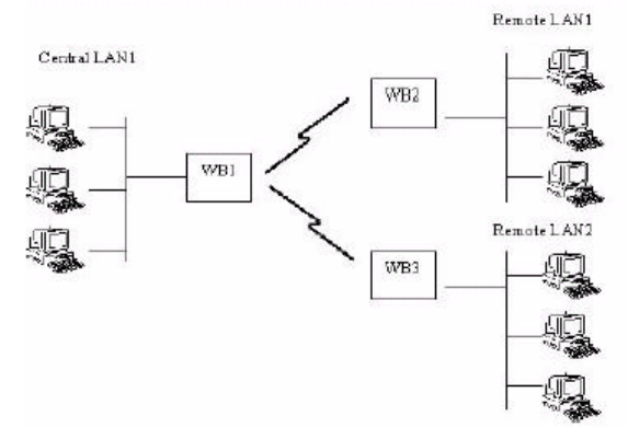
• Authorization - Using this submenu the Administrator can change the password which referred
to the community field (Figure 3-2. Connecting to the UAT -AP using the SNMP Manager) for the
User and the Administrator Authority (Figure 3-15)
WL-3111 User’s Manual
18
Figure 3-15. Authority Configuration window
Commands menu: Under this menu there are two submenus.
• Reset Device - You can reset the Access Point. This action takes place after a user makes
configuration changes in order to initiate the changes.
• Restore Default - You can restore the factory default values of the Access Point.
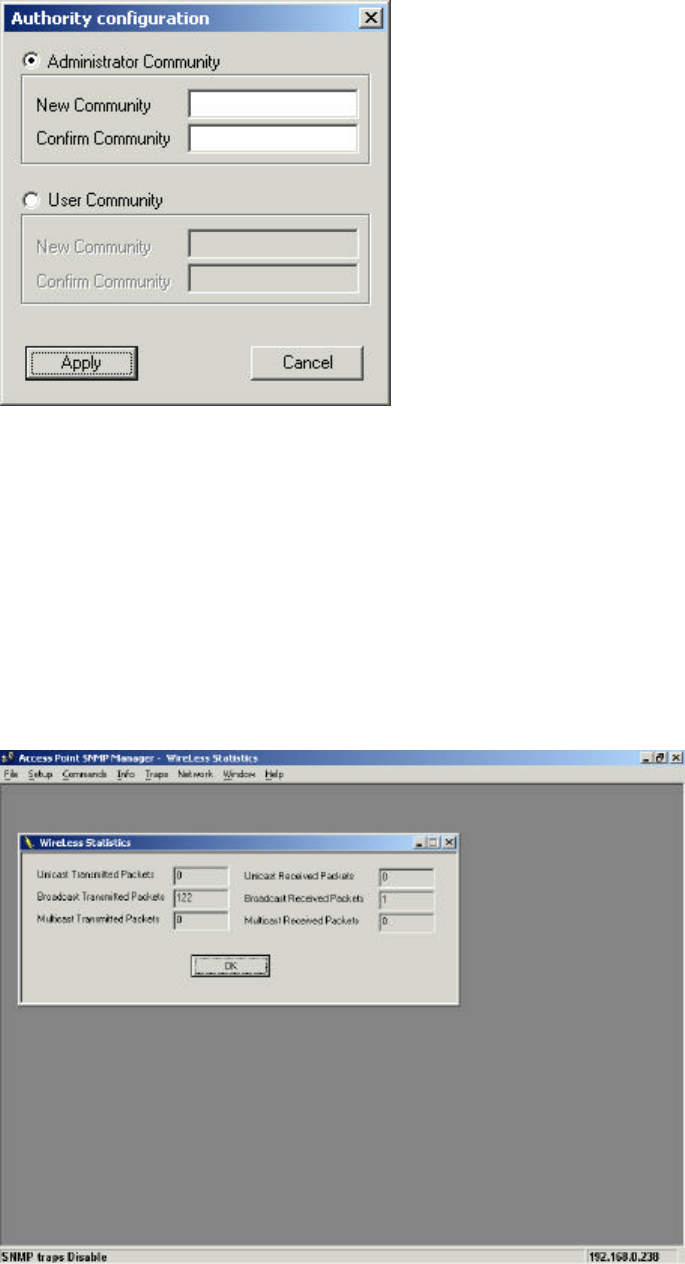
Info menu: Using this menu you can view a limited number of statistics by choosing the “SNMP -
Short View” of the “Change Mode” software. There are the following submenus:
Wireless statistics: This submenu reports the statistics concerning the unit’s Wireless activity
(Figure 3-16).
Figure 3-16. Wireless Statistics-Short View
WL-3111 User’s Manual
19
The meaning of the fields, concerning all the statistics, is given in the following table.
Table 3-2. Wireless Statistics - Short View
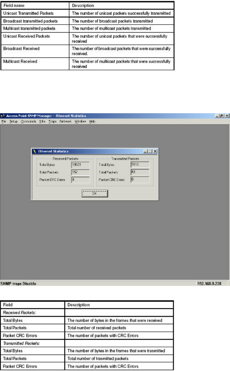
Ethernet statistics: This submenu reports the statistics concerning the unit’s Ethernet port
activity (Figure 3-17). The meaning of the fields, concerning all the statistics is given in the
following table.
Figure 3-17. Ethernet Statistics-Short View
Table 3-3. Ethernet Statistics-Short View
WL-3111 User’s Manual
20
Traps menu: Provides information for trap messages
• View Record - You can see additional information for every Trap Message
Network menu: Provides information about the Network. Under this menu there is only the
Associated Station submenu.
• Associated stations - Using this submenu you can view the MAC Addresses of the Associated
stations with the Access Point.
Window menu: Under this menu there are the following submenus
• Cascade - All opened windows are arranged on the desktop in a cascade fashion.
• Tile - All open windows are visible on the desktop.
Help menu: Provides on line help about the application.
WL-3111 User’s Manual
21
4. Access Point Firmware Upgrade
The WL-3111 AP firmware upgrade can be done through the Ethernet port by using the TFTP
Client Utility.
4.1 Using the Ethernet Port/Wireless Port
In order to upgrade the firmware of the WL-3111 AP through the Ethernet port/Wireless port, you
must first install the TFTP Client Utility, which is a powerful and reliable tool used for the remote
firmware upgrade of the Access Point through the Ethernet/Wireless port.
4.1.1 How to Install the TFTP Client
In order to install the TFTP Client Utility you need to run the program “setup.exe” which you will
find into the “TFTP” sub-folder of the “Utilities” folder in your CD. Follow the instructions of the
set-up program and select the directory where the application will be installed. Finally, a window
appears indicating the completion of the installation.
Additionally, you need to use the “Change Mode” software tool which provides the possibility to
change from “TFTP Client - User Mode” to “TFTP Client - Production Mode” (Figure 3-1). For
more details see paragraph 4.1.1.1.
4.1.2 Using the TFTP Client/User Mode
Note: Before using the TFTP Client for upgrading the firmware of the ATMEL-AP, verify that the
Access Point IP address has been set-up following the procedure described in the 2 Setting the
IP Address of the Access Point.
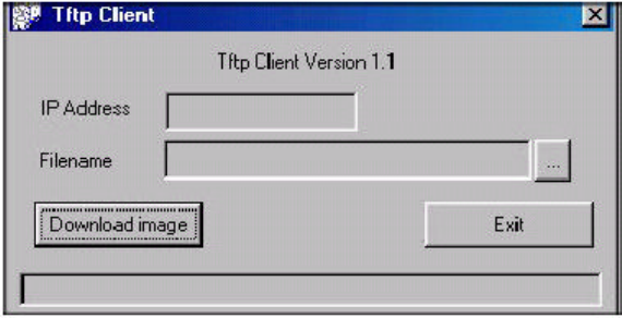
Go to the Windows task bar, choose Start -> Programs -> TFTP Client. The following window
(Figure 4-1) appears.
Figure 4-1. ATMEL TFTP Client Utility
Type the IP address of the Access Point in the first edit box of the panel. Then, browse for the
appropriate file (e.g bridge.rom) by pressing the “Browse (three dots)” button. Finally press the
"Download" image” button to download the firmware (Figure 5-2).
WL-3111 User’s Manual
22
Figure 4-2. The IP address, browse for the file Bridge.rom and download
The Firmware Download procedure will be completed successfully if a message in the right
bottom corner appears indicating “Firmware download has been completed”. If you receive the
message “Timed Out”, in the right bottom corner, during the firmware download procedure, you
need to check if the Access Point is powered on and if it has a valid IP address. In order to check
the validity of the IP address you must ping the Access Point.
If you receive the message “Flash Programming in progress” during the firmware download
procedure you shouldn’t power off the Access Point. In order to close the application press the
"Exit" button.
Note: If the download procedure has not been completed successfully you must try again but
before starting the download you need to confirm that you are using the correct firmware file.
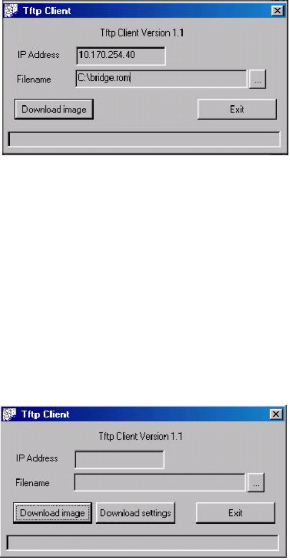
4.1.3 Using the TFTP Client/Production Mode.
When you select the “TFTP Client - Production Mode” of the “Change Mode Software” the
window of Figure 4-1 has the additional button “Download settings” in order to download the
Access Point settings separately (Figure 4-3).
Figure 4-3. TFTP - Client Production Mode
4.1.4 How to Uninstall the TFTP Client
In order to uninstall ATMEL TFTP Client you go to the Windows task bar, choose Start ->
Programs -> TFTP Client -> Uninstall TFTP Client.
WL-3111 User’s Manual
23
FCC Regulation
INTERFERENCE INFORMATION: PART 15 OF FCC RULES
Some telephone equipment generates and uses radio frequency energy, which if not
properly installed, may cause interference to radio and television reception.
This unit has been tested and found comply with the limits for a Class B computing
device in accordance with Part 15 of the FCC rules. These specifications are designed to
provide reasonable protection against such interference in a residential installation.
However, there is no guarantee that interference will not occur in a particular installation.
If this equipment does cause interference to radio or television reception, when it’s in use,
the user is encouraged to try to correct the interference by one or more of the following
measures:
A. Where it can be done safely, reorient the radio or TV receiving antenna.
B. To the extent possible, relocate the television, radio, or other receiver with respect
to telephone equipment.
C. If your telephone product runs on AC power, plug your product into an AC outlet
that’s not on the same circuit as the one used by the radio or television.
SAFETY INFORMATION
Your device contains a low power transmitter. When device is transmitted it sends out
radio frequency (RF) signal.
CAUTION: To maintain compliance with FCC’s RF exposure guidelines, this equipment
should be installed and operated with minimum distance 20cm between the radiator and
your body. Use on the supplied antenna. Unauthorized antenna, modification, or
attachments could damage the transmitter and may violate FCC regulations.