UBS Axcera 334B 2000-Watt VHF Low Band Transmitter User Manual 334B
UBS-Axcera 2000-Watt VHF Low Band Transmitter 334B
UserManual.wiki
>
UBS Axcera
>
334B User Manual
Compiled Manual 334B
Navigation menu
Upload a User Manual
Namespaces
Wiki Guide
HTML
PDF
Info
Views
User Manual
Discussion / Help
Navigation
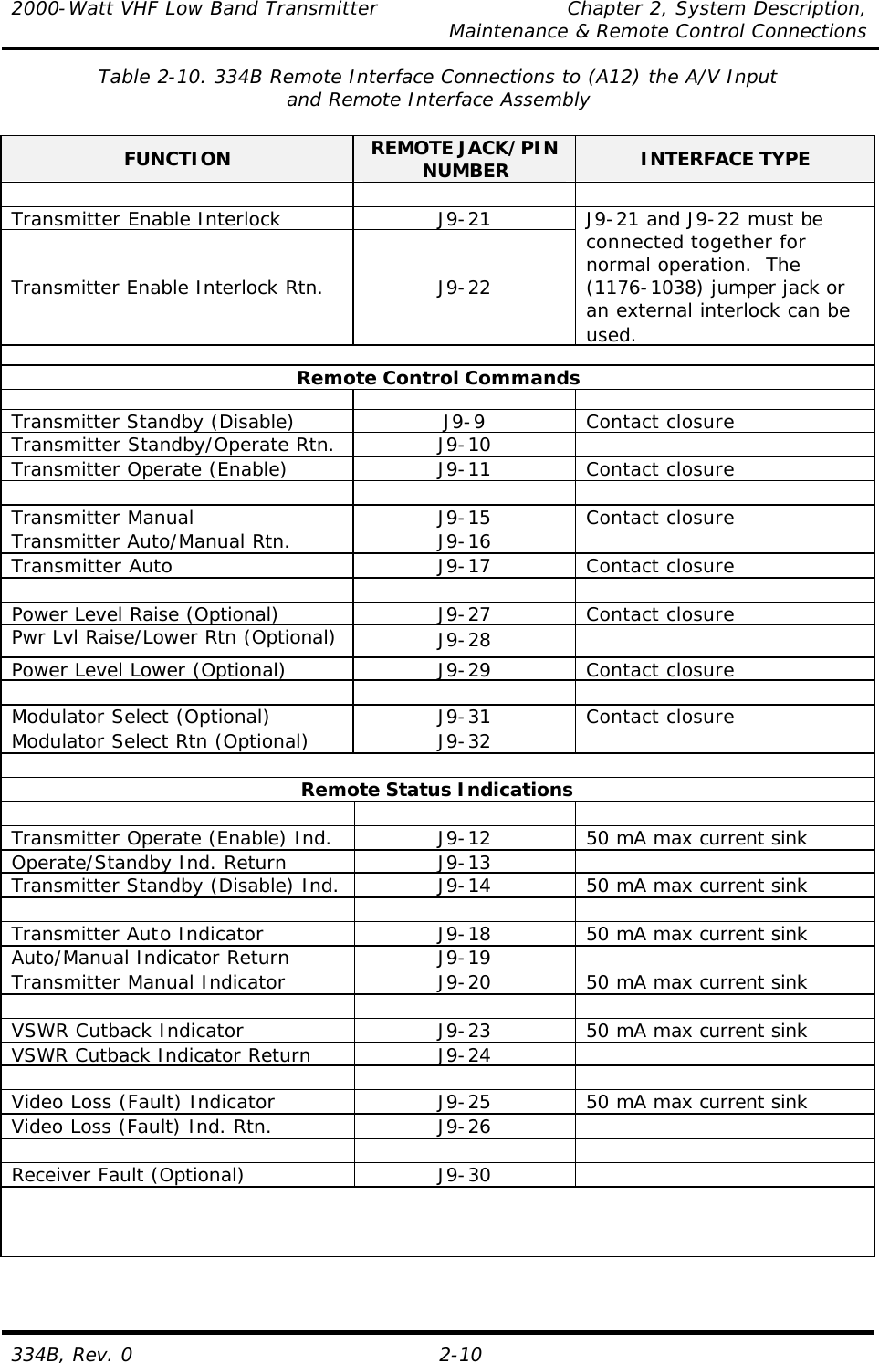

![2000-Watt VHF Low Band Transmitter Chapter 4, Circuit Descriptions 334B, Rev. 0 4-27 determines the length of time between the sending of the identification code. R14 is adjusted to set this time interval. R14, fully CW, is the longest interval between identification calls, approximately eight minutes. R14, fully CCW, is the shortest interval between the sending of the code (approximately 10 seconds). U6B is an amplifier connected to the output of U5, which turns the LED DS1 on and off at the rate set by R2. This gives the operator a visual indication that the FSK identifier board is operating and at the rate at which it is operating. The data output of U5, which is serial, is connected to U6A, whose output shifts low and high, and is applied to the VCXO board, which shifts the frequency according to the programming of U5. The deviation of the shift is adjusted by R4 and is typically set at 1 kHz. Once R4 is set, R9 is re-adjusted to -1.5 VDC at J3-2. The +12 VDC from an external power supply enters the board at J1, pin 3. The voltage is fed through RF choke L1 and is filtered by C1 before being applied to the rest of the tray. The +12 VDC is also applied to U7, which is a voltage regulator that regulates its output at +5 VDC. The +5 VDC is fed to the ICs on the board. The -12 VDC from an external power supply enters the board at J1, pin 5. The voltage is fed through RF choke L2 and filtered by C2 before being applied to the rest of the tray. 4.1.12 (Optional) (A12) IF Attenuator Board (1150-1201; Appendix D) The IF attenuator board is operated with the FSK identifier board to produce an amplitude modulated aural IF signal for broadcasting the required FCC station identification call sign at the proper time intervals. The board contains a pin-diode attenuation circuit that consists of CR1 and the two resistors R2 and R3. The bias output of the FSK identifier board is applied to J3 of the IF attenuator board. As the bias applied to J3 increases and decreases, the amplitude of the aural IF signal, which enters the board at J1 and exits the board at J2, will increase and decrease. This produces an amplitude-modulated IF signal at J2, the aural IF output jack of the board. 4.2 (A6, A7 and A11) Low Band VHF Amplifier Trays (1304363; Appendix C) The low band VHF amplifier tray is adjusted at the factory for use as a visual + aural RF amplifier tray. The tray has approximately 55 dB of gain at the frequency of the VHF low band channel and will take the typical +7 dBm Visual – 3dBm Aural input and amplify it to an output level of approximately +58.8 dBm. As a visual + aural amplifier, the tray is calibrated for 750 watts peak of sync visual plus 10 dB aural power (75 watts) that is equal to a 100% meter reading. The tray is made up of the boards and assemblies listed in Table 4-1. Table 4-1. VHF Amplifier Tray Boards and Assemblies MAJOR ASSEMBLY DESIGNATOR BOARD/ASSEMBLY NAME DRAWING NUMBER A2-A1 Phase shifter board (mounted in [A2] an RF enclosure assembly) 1198-1602 A2-A2 Filter/amplifier board (mounted in [A2] an RF enclosure assembly) 1198-1606 A3-A1 Low band VHF amplifier board (mounted in [A3] an RF enclosure 1198-1605](https://usermanual.wiki/UBS-Axcera/334B/User-Guide-451444-Page-53.png)
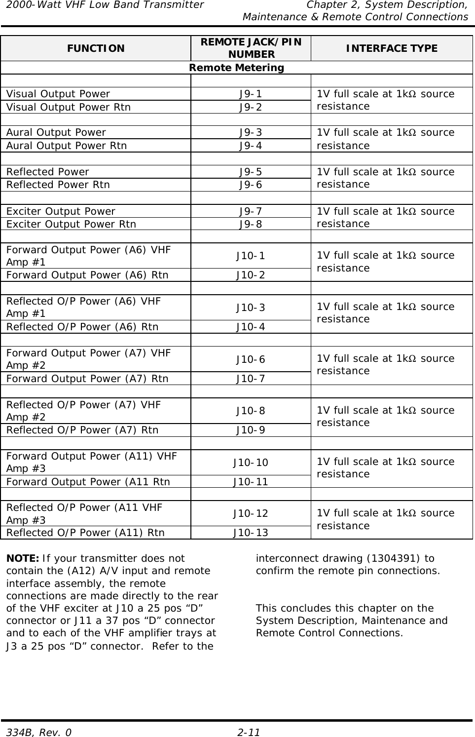
![2000-Watt VHF Low Band Transmitter Chapter 4, Circuit Descriptions 334B, Rev. 0 4-28 assembly) MAJOR ASSEMBLY DESIGNATOR BOARD/ASSEMBLY NAME DRAWING NUMBER A3-A2 Overdrive protection board (mounted in [A3] an RF enclosure assembly) 1198-1601 A3-A3 3-way splitter board (mounted in [A3] an RF enclosure assembly) 1198-1608 A4-A1, A4-A2 and A4-A3 Three low band VHF amplifier pallets (mounted in [A4] an RF enclosure assembly) P400-VHF-L-18 1304348 A5-A1 3-way combiner board (mounted on [A5] the combiner heatsink assembly) 1198-1626 A13 AGC control board 1142-1601 A8 Current metering board 1304362 A10 +30 VDC switching power supply assembly PM3329B-5-1-R-2-E 1301504 The on-channel RF input signal (+7 dBm Visual –3 dBm Aural) enters the rear of the tray at the BNC jack J1 and is fed through J1 of the (A2) enclosure assembly to J1 of (A2-A1) the phase shifter board (1198-1602). The board provides a phase shifter adjustment of the RF signal that is needed to provide maximum output during the combining of the three VHF amplifier trays in the 3 way combiner. The front panel mounted phase shift potentiometer R2 (A7) connects to J3 on the board and controls the phase of the RF signal. If the input signal level to the phase shifter board falls below a preset level, a high, which is an input fault, connects from J5 of the board to J14 on the AGC control board. When an input fault occurs, the AGC control board generates a fault output at J1, which is connected to J4 on the filter/amplifier board. The fault cuts back the RF signal level using the pin-diode attenuator circuit on the filter/amplifier board. The phase-controlled output at J2 of the phase shifter board (+7 dBm) is directed to J7, the input jack of the (A2—A2) filter amplifier board (1198-1606) that is made up of two circuits. The first circuit is a channel filter that is adjusted for the desired channel frequency and bandwidth. The filtered output (+5 dBm) is connected to the second circuit that contains two amplifiers. The RF connects through a pin-diode circuit to the amplifier IC U1. The voltage applied to J4, which is the external control jack of the board, controls the amplitude of the RF signal through the pin-diode attenuator circuit. Jumper W1 on J5 should be between pins 2 and 3, which provide external control, through J4, of the gain of the board, as well as the output level of the tray. R9 is the manual gain pot that is in the circuit when the jumper W1 is between pins 1 & 2. The front panel mounted gain pot R3 (A6) connects to the AGC control board and is used to adjust the AGC pin-attenuator bias voltage that connects to J4 on the filter/amplifier board. The RF signal, after the pin-attenuator circuit, is amplified by the second amplifier stage Q1 to about +19.5 dBm; this signal is connected to the output of the board at J2. The RF output of the filter/amplifier board connects to J2 of (A3) a RF enclosure that contains the low band VHF amplifier board, the overdrive protection board and the 3-way splitter board. The RF from J2 on the enclosure connects to](https://usermanual.wiki/UBS-Axcera/334B/User-Guide-451444-Page-54.png)
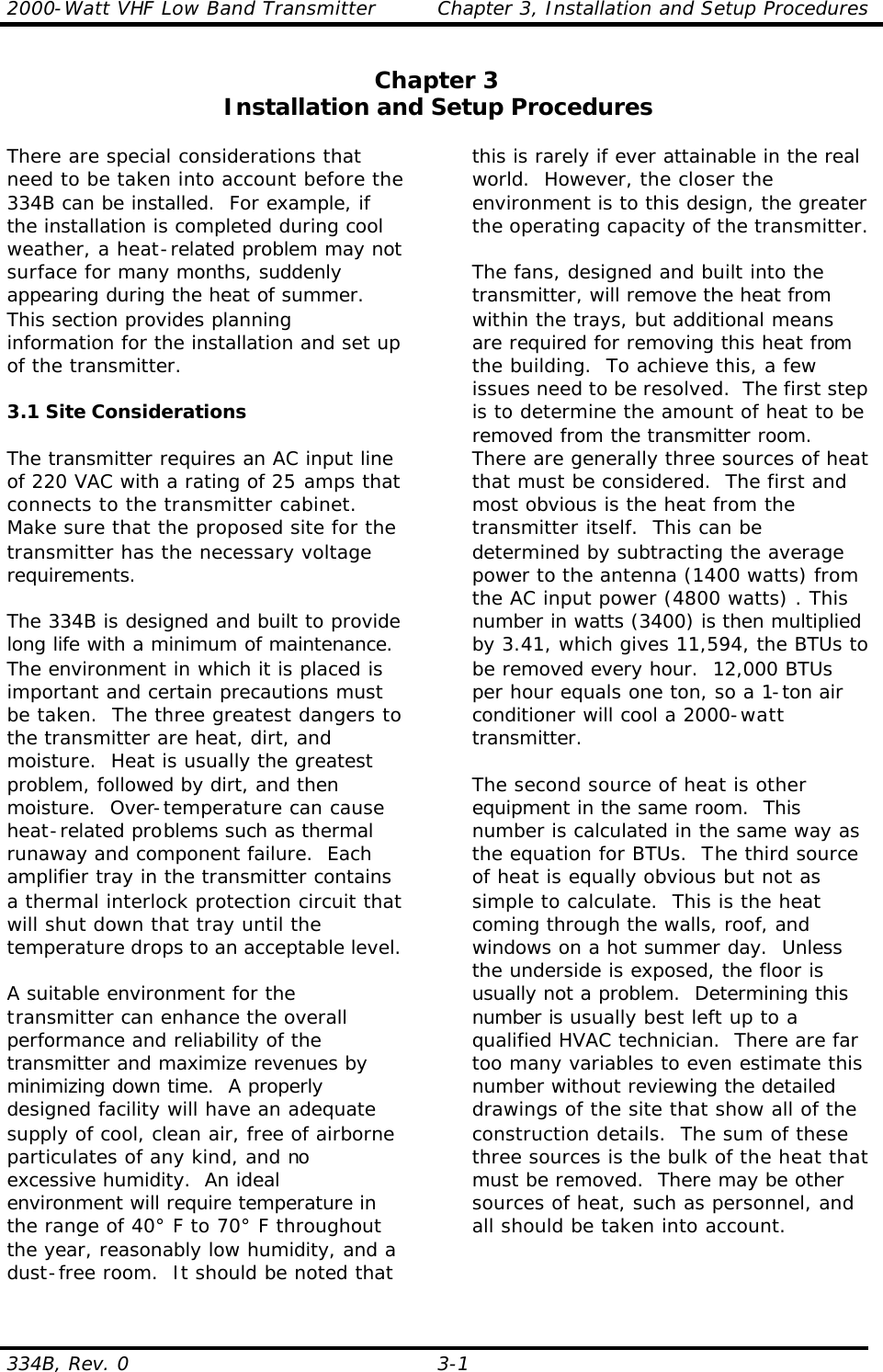
![2000-Watt VHF Low Band Transmitter Chapter 5, Detailed Alignment Procedures 334B, Rev. 0 5-5 (1142-1601) in Manual. The idling currents for the amplifier boards are adjusted with no RF drive applied. Remember to put S1 back to the Auto AGC position after any adjustments. Auto AGC is the normal position during operation of the transmitter. Connect a dummy load with a rating of at least 750 watts to J2, the RF output jack of the tray being aligned, before beginning the alignment procedure. Switch the VHF amplifier tray on and the transmitter to operate. 5.6.1 (A13) AGC Control Board (1142-1601; Appendix D) Using a calibrated wattmeter, check that the tray is operating at the rated power. Remove the sample forward power connection J4 from the (A13) AGC control board (1142-1601). The output power level should drop to 20% because of the VSWR cutback and DS4, the VSWR Cutback LED, should be illuminated. The front panel Module Status LED should not be lit. Reconnect J4 and adjust R59 so that it begins to cut back on the output power level when the reflected level increases above 20%. In the Power Supply Voltage position, the front panel meter is calibrated to +30 VDC using R86 on the AGC control board. 5.6.2 (A2-A1) Phase Shifter Board (1198-1602; Appendix D) There are no adjustments to (A2-A1) the phase shifter board (1198-1602). The front panel has adjustments for phase that are made during the amplifier array setup procedure. Typically +7 dBm input and +7 dBm output. 5.6.3 (A2-A2) VHF Filter/Amplifier Board (1198-1606; Appendix D) The (A2-A2) VHF filter/amplifier board (1198-1606) has approximately 14 dB of gain. Tune the channel filter capacitors C29 and C20 (loading), C26 and C23 (center frequency), and C24 (coupling) at J6 on the board for the best response. Set voltage adjust pot R19 for +24 VDC at the anode of CR5. The idling current, no RF drive applied, of the device Q1 is set for 250 mA. To set the current, remove the RF drive, measure the voltage across R16 (a 1Ω resistor on the filter/amplifier board) and adjust R13 for .25 volts (using Ohms’ Law: [E=I x R] : [E=250 mA x 1 Ω] : E=250 mV). Typically the board has a +7 dBm input and a +19.5 dBm output level. 5.6.4 (A3-A1) VHF Low-Band Amplifier Board (1198-1605; Appendix D) The (A3-A1) VHF low-band amplifier board (1198-1605) has 22 dB of gain and is biased for 3 amps of idling current, no RF drive applied. Adjust voltage adjust pot R10 for +24 VDC at pin 0 of the regulator IC U1. To set the bias, remove the RF drive from the board, measure the voltage across R6 and R7 (two 1Ω resistors in parallel on the high-band driver board), and adjust R4 for 1.5 volts (using Ohms’ Law: [E=I x R] [E=3 amps x .5 Ω] : E=1.5 volts). Connect a spectrum analyzer to output jack J2 on the board and adjust C15 for peak output. Typically +19.5 dBm input and +41.5 dBm output. 5.6.5 (A3-A2) Overdrive Protection Board (1198-1601; Appendix D) The typical input level to the (A3-A2) overdrive protection board (1198-1601) is +41.5 dBm during normal operation with a typical output of +41.3 dBm. To set up the overdrive circuit, check that the output power level of the transmitter is at 100% and adjust R11 on the board for a reading of .4 VDC at TP1. Increase the output power level of the transmitter](https://usermanual.wiki/UBS-Axcera/334B/User-Guide-451444-Page-63.png)
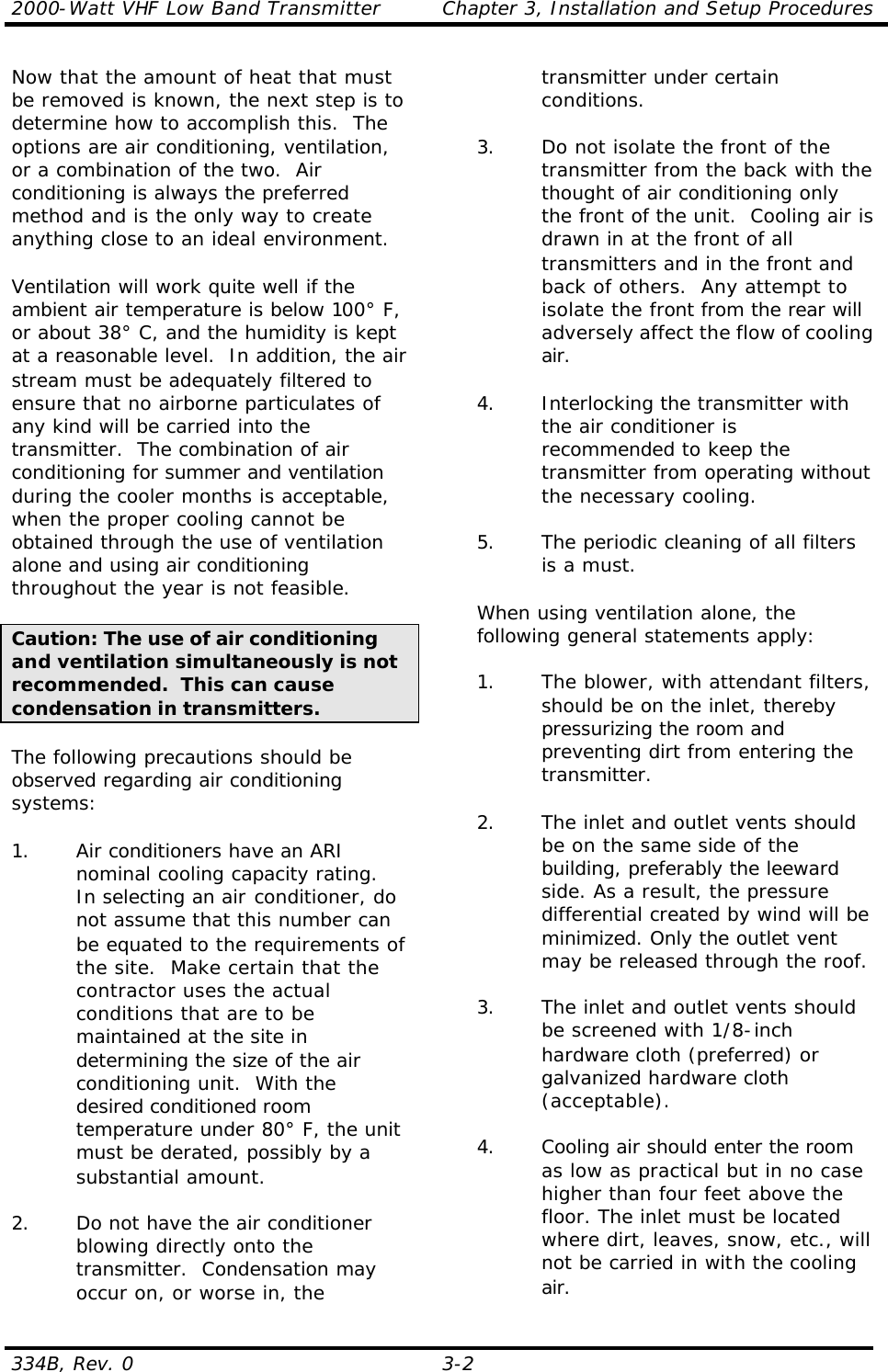
![2000-Watt VHF Low Band Transmitter Chapter 5, Detailed Alignment Procedures 334B, Rev. 0 5-9 5.10 (A8) 3-Way Combiner Assembly (1065241; Appendix C) There are no adjustments to (A8) the 3 way combiner assembly. 5.11 (A14) Bandpass Filter Assembly (1304388; Appendix C) The harmonic and bandpass filters are factory swept by the filter manufacturer and should not be tuned without the proper equipment. Do not attempt to tune the filters without a sweep generator or, preferably, a network analyzer. If tuning is required, consult the Axcera Field Support Department before attempting to make any adjustments. 5.12 Complete Board Level Alignment Procedures for the VHF Low Band Exciter NOTE: The following procedure should be fallowed only if complete alignment of the VHF exciter tray is needed. 5.12.1 (Optional) 4.5-MHz Composite Input Kit If the (optional) 4.5-MHz composite input kit is purchased, the tray is capable of operating by using either the 4.5-MHz composite input or the baseband audio and video inputs. The kit adds the (A24) composite 4.5-MHz filter board (1227-1244; Appendix D) and the (A25) 4.5-MHz bandpass filter board (1265-1307; Appendix D) to the transmitter. When the 4.5-MHz intercarrier signal generated by the 4.5-MHz composite input has been selected by the 4.5-MHz composite input kit, the 4.5-MHz generated by the aural IF synthesizer board is not used. When the 4.5-MHz intercarrier signal generated by the baseband video and audio inputs with baseband has been selected by the 4.5-MHz composite input kit, the composite 4.5-MHz filter board and the 4.5-MHz bandpass filter board are not used. The tray has been factory tuned and should not need any alignments to achieve normal operation. To align the tray for the 4.5-MHz composite input, apply the 4.5-MHz composite input, with the test signals used as needed, to the video input jack (J1 or J2 [loop-through connections]) on the rear of the tray. Select the 4.5-MHz composite input by removing the baseband select from J18-6 and J18-7 on the rear of the tray. To align the exciter using baseband video and audio inputs, apply the baseband video, with the test signals used as needed, to the video input jack (J1 or J2 [loop-through connections]) and the baseband audio to the proper baseband audio input on the rear of the tray. For balanced audio input, connect TB1-1(+), TB1-2(-), and TB1-3 (GND). For composite/stereo audio, connect the composite audio input jack (J3 or J13 [loop-through connections]) and connect a baseband select from J18-6 and J18-7 on the rear of the tray. 5.12.2 (A6) Delay Equalizer Board (1227-1204; Appendix D) The jumper W1 on J5 of the sync tip clamp/modulator board, if present, must be in the Enable position between pins 2 and 3. NOTE: This board has been factory tuned and should not be retuned without the proper equipment. To tune this board: 1. Connect a sinX/X test signal into jack J1-2 on the delay equalizer board. 2. Monitor the video output of the board, at the video sample jack J2, with a video measuring set, such as the VM700, adjusted to measure group delay. 3. Tune the four stages of the board using the variable inductors (L1-L4)](https://usermanual.wiki/UBS-Axcera/334B/User-Guide-451444-Page-67.png)