UBS Axcera 420A Low Power Television User Manual Chapter 2
UBS-Axcera Low Power Television Chapter 2
UserManual.wiki
>
UBS Axcera
>
420A User Manual
>
Chapter 2
Contents
1.
Table of contents
2.
Chapter 1
3.
Chapter 2
4.
Chapter 3
5.
Chapter 4
6.
Appendix A list of drawings
7.
Appendix A drawing
8.
Appendix B drawing list
9.
Appendix B drawing
Chapter 2
Navigation menu
Upload a User Manual
Namespaces
Wiki Guide
HTML
PDF
Info
Views
User Manual
Discussion / Help
Navigation
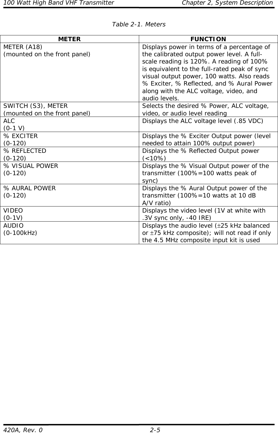
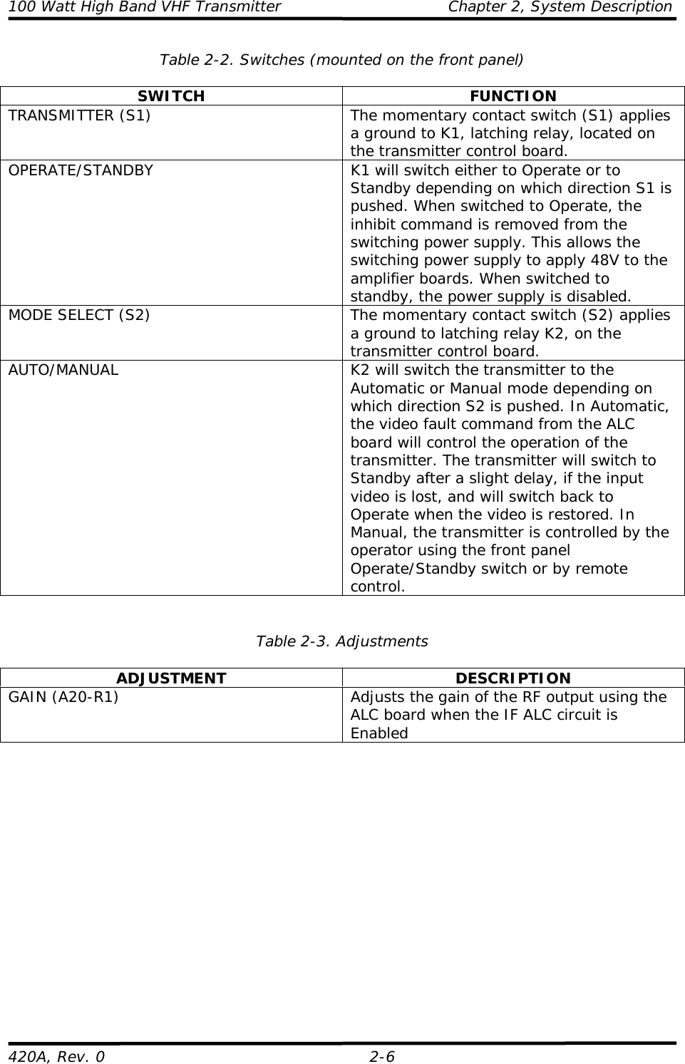
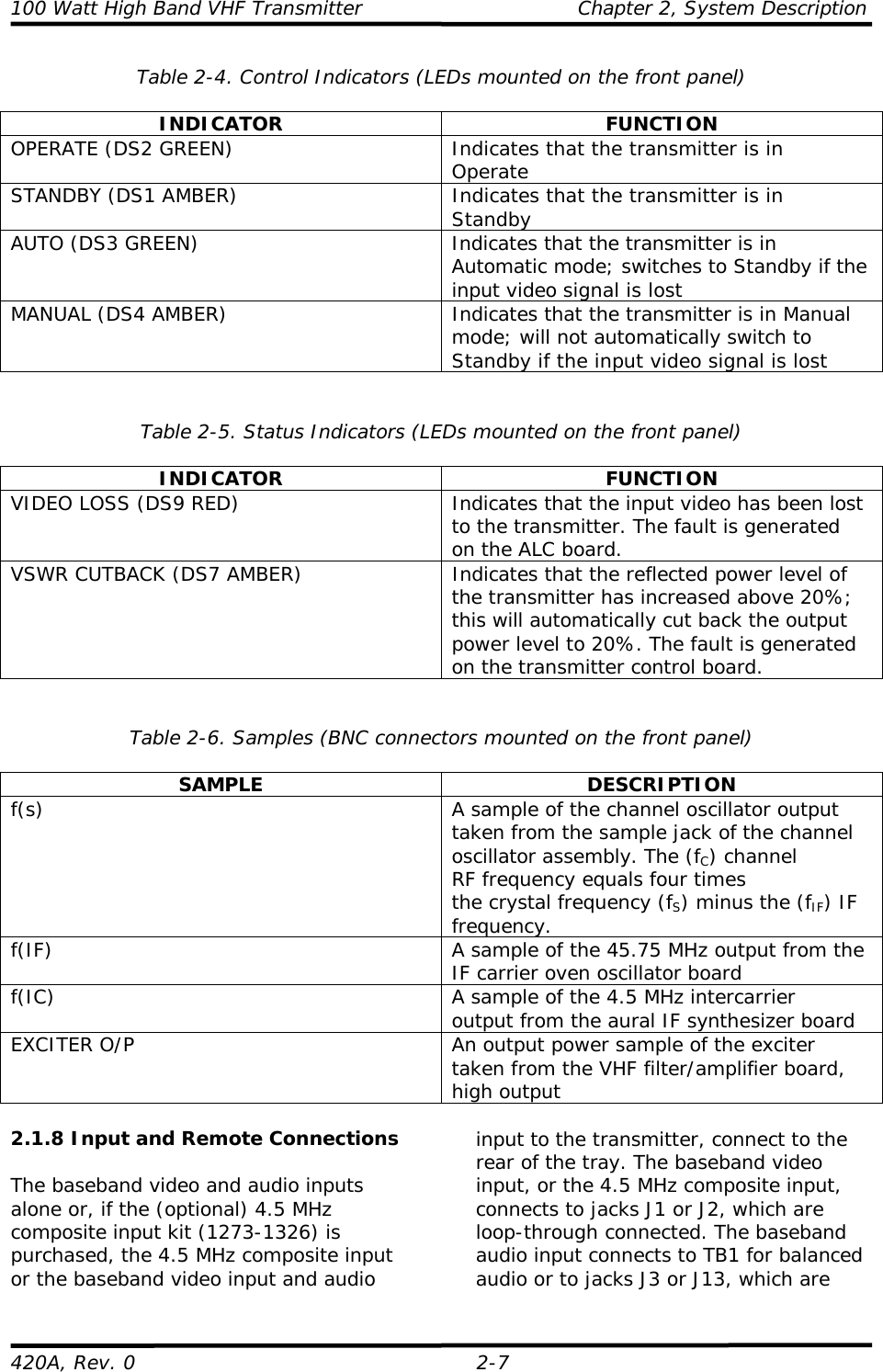
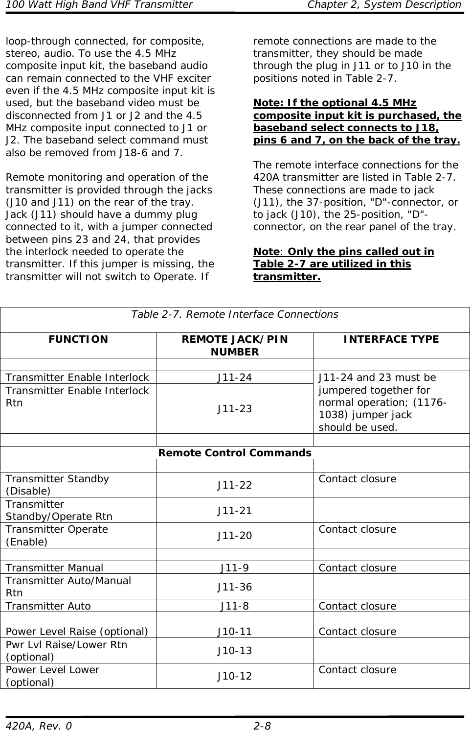
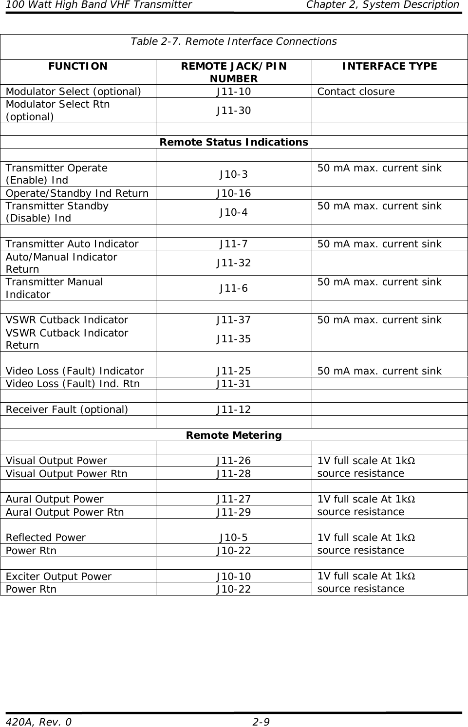
![100 Watt High Band VHF Transmitter Chapter 2, System Description420A, Rev. 0 2-42.1.7 Control and StatusMeters, switches, and LED indicators aremounted on (A17) the transmitter controlboard (1068933). The control board isattached to the back of the front panel toallow for the switches and the LEDs to beoperated or viewed from the front of thetray. The (S1) Operate/Standby switchcontrols the output of the transmitter byapplying or removing the inhibitcommand to the switching power supplythat provides the DC supply voltages tothe amplifier section.In Operate, the green LED (DS2) is onand the inhibit command is removed.When in Standby, the amber LED (DS1)is on and the inhibit command is applied.Switch (S2) is an Automatic/Manualswitch that controls the operation of thetransmitter by the presence of the videoinput signal. When the switch is inAutomatic, the green LED (DS3) is litand, if the video input signal is lost, thetransmitter automatically switches toStandby after a short delay. When thevideo input signal returns, thetransmitter immediately switches back toOperate. In Manual, the amber LED(DS4) is lit and the operation of thetransmitter is controlled by the frontpanel switches. During normal operationof the transmitter, switch S2 should be inthe Auto position.The front panel of the tray also has LEDsthat indicate Video Fault (Loss) (red LED[DS9]) and VSWR Cutback (amber LED[DS7]). The meters, switches, and LEDsfound in the 420A are described in thefollowing tables.](https://usermanual.wiki/UBS-Axcera/420A.Chapter-2/User-Guide-80249-Page-4.png)