UBS Axcera 837B-5 5000-Watt UHF Translator User Manual 315944
UBS-Axcera 5000-Watt UHF Translator 315944
UserManual.wiki
>
UBS Axcera
>
837B-5 User Manual
>
Chapter 2
Contents
1.
Title Page
2.
Table of Contents
3.
Chapter 1
4.
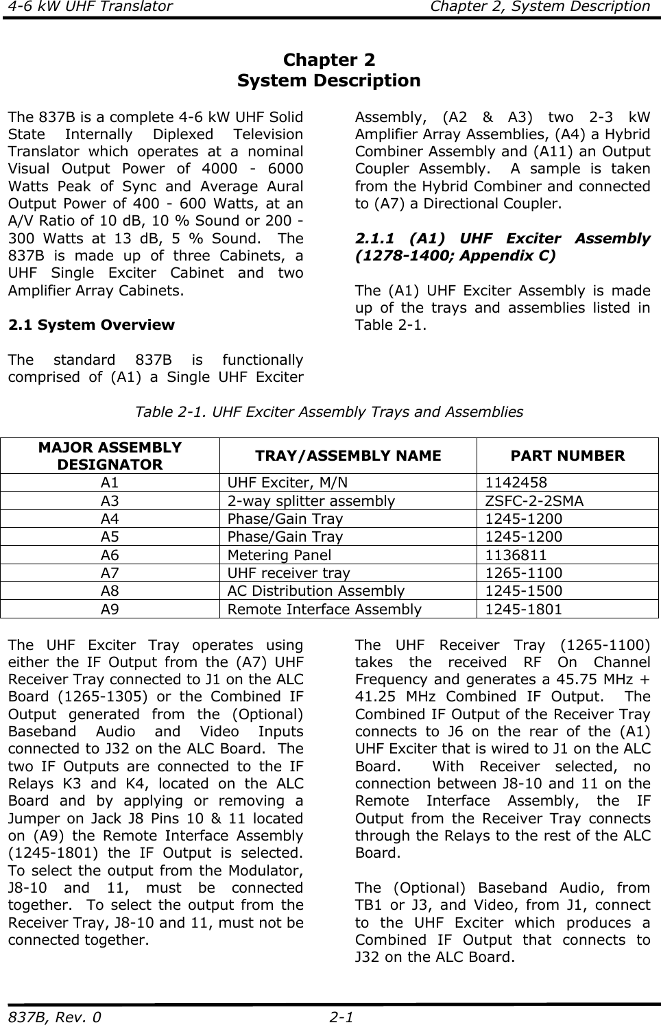
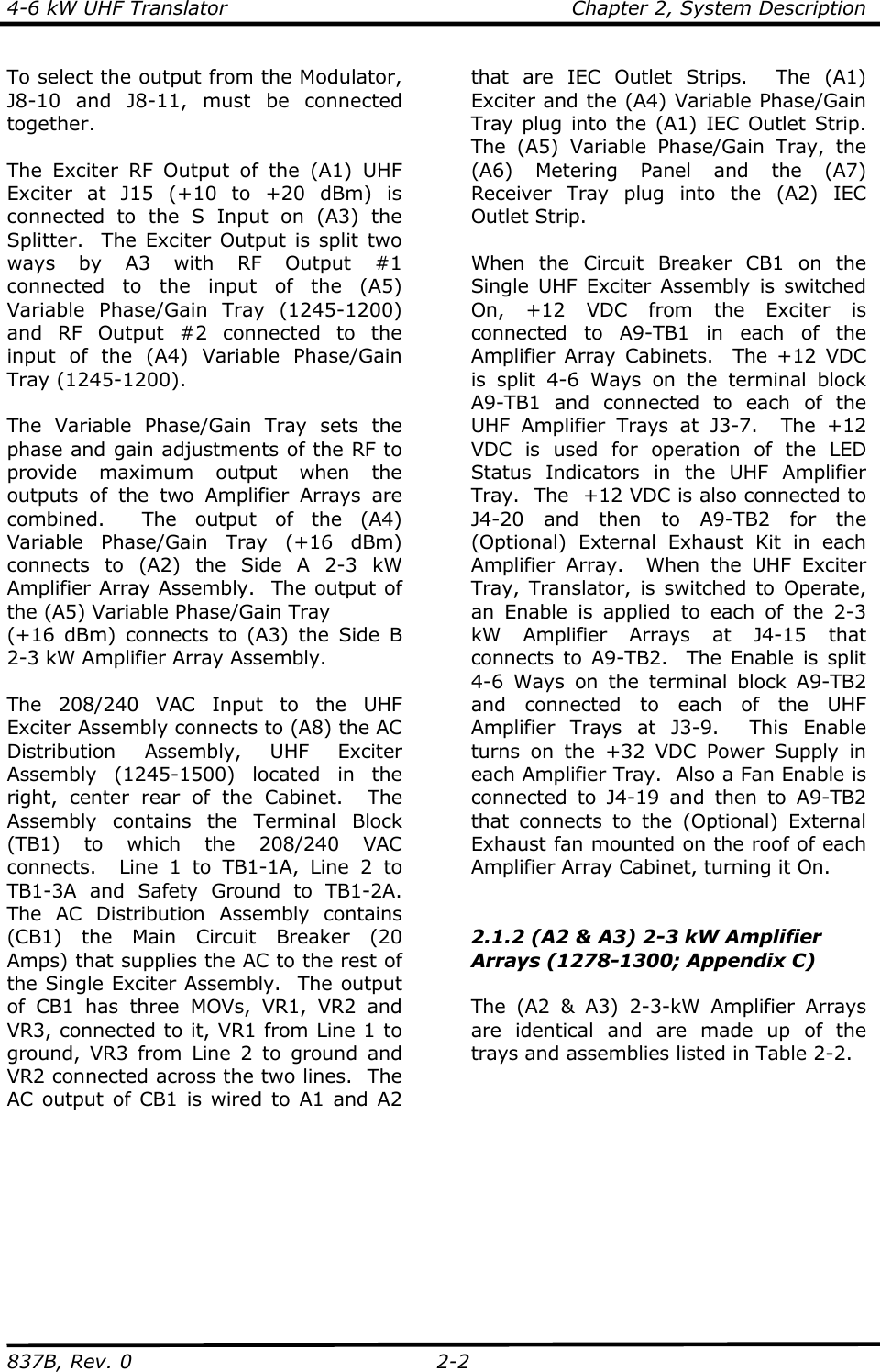
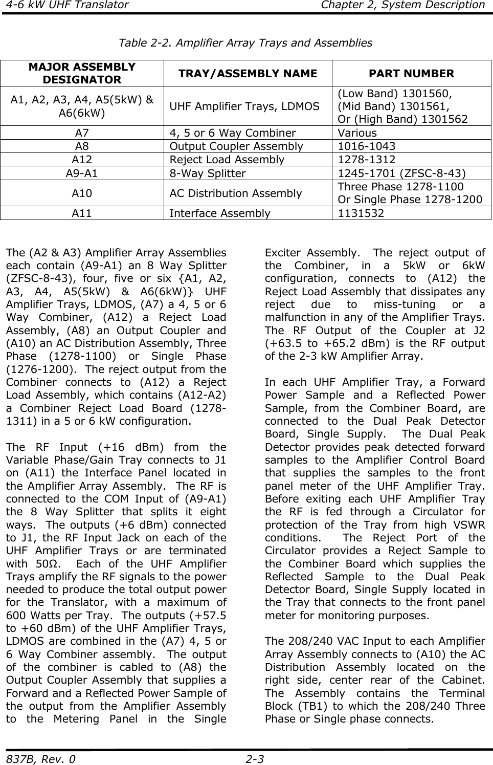
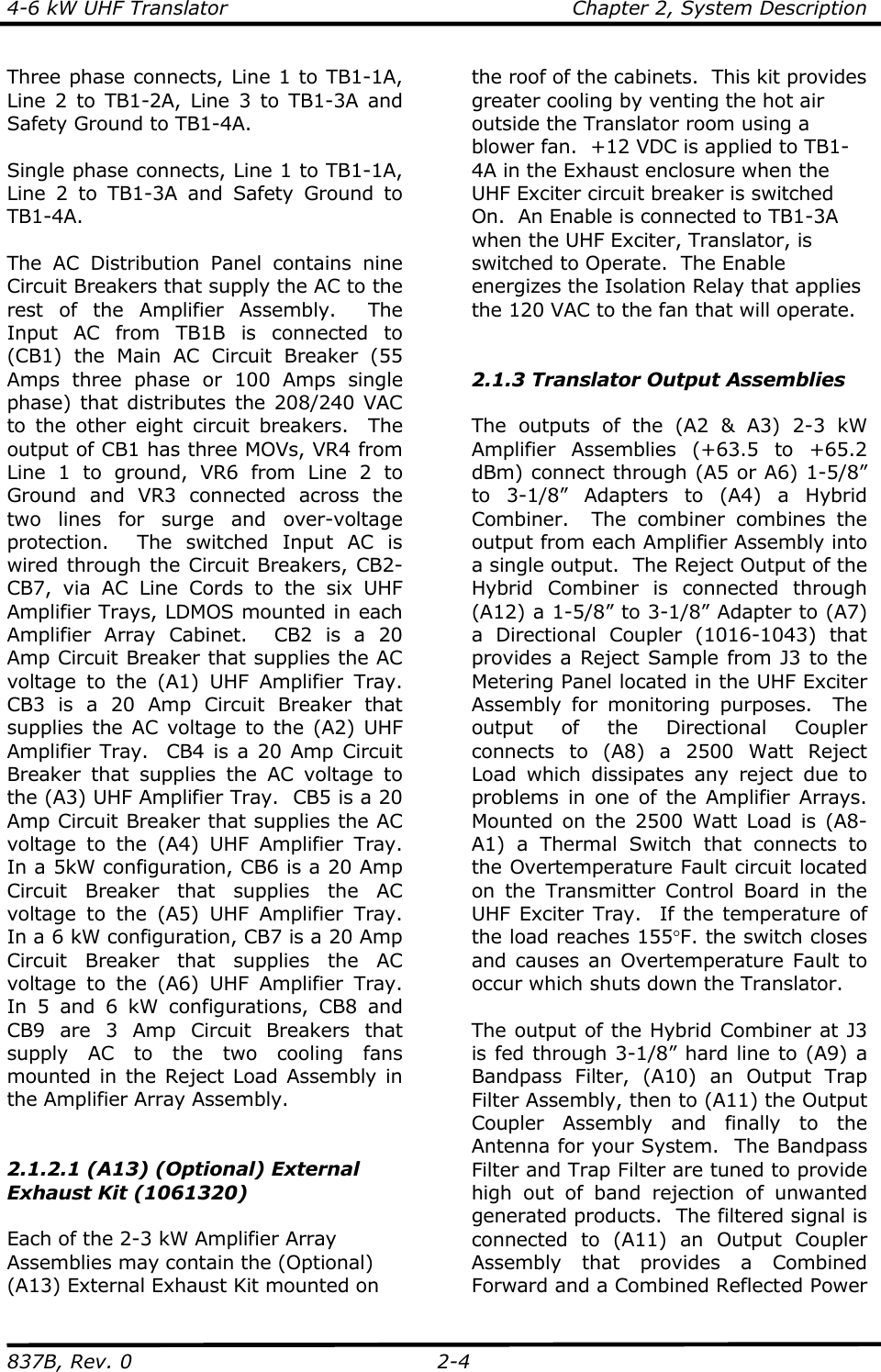
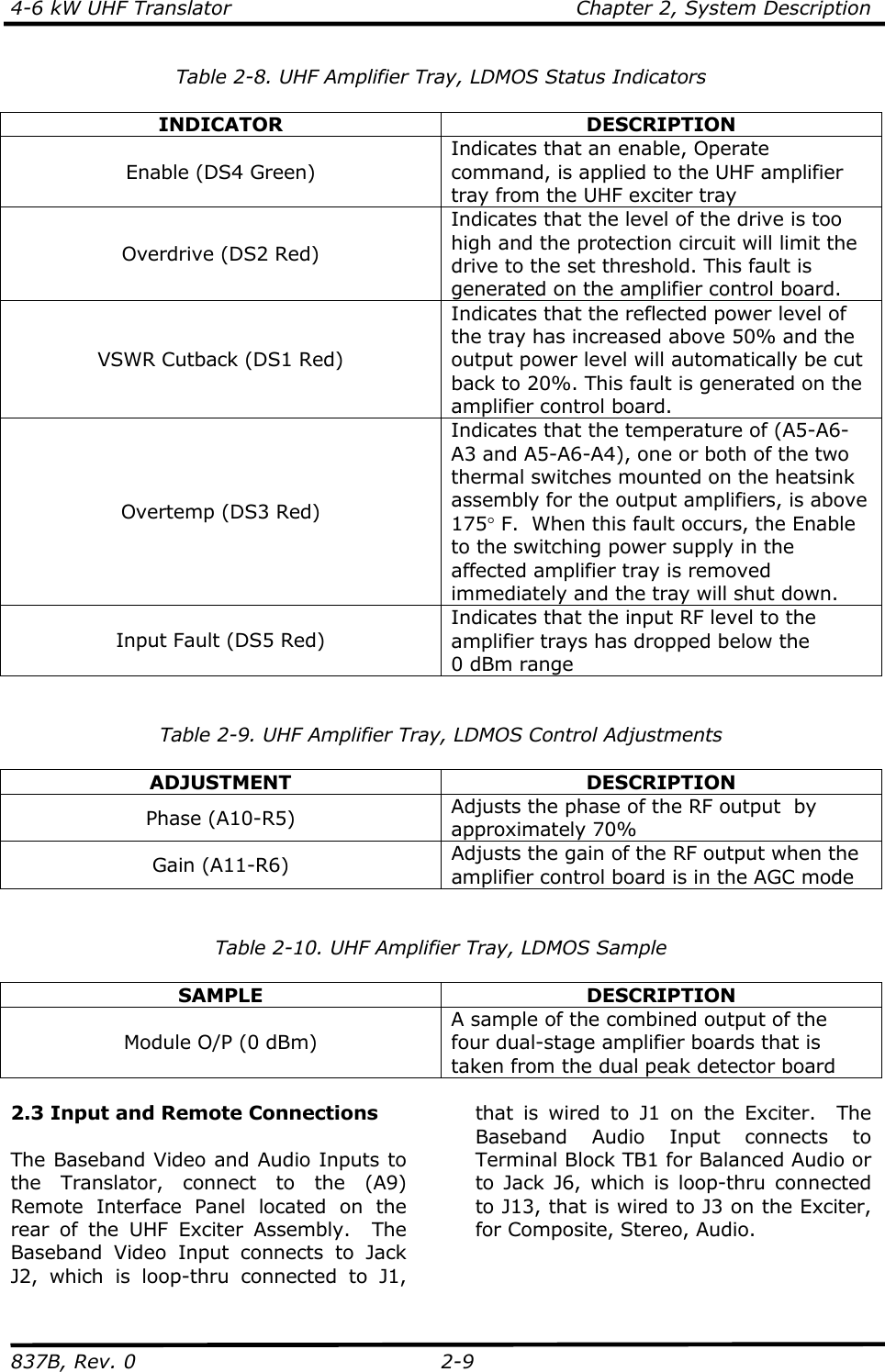
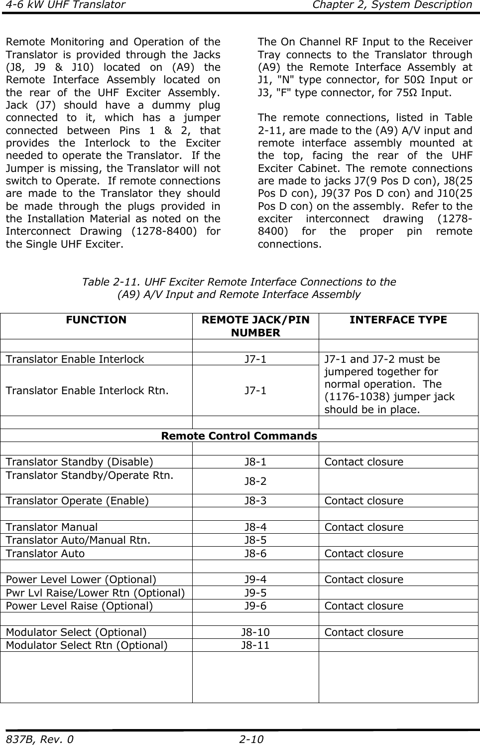
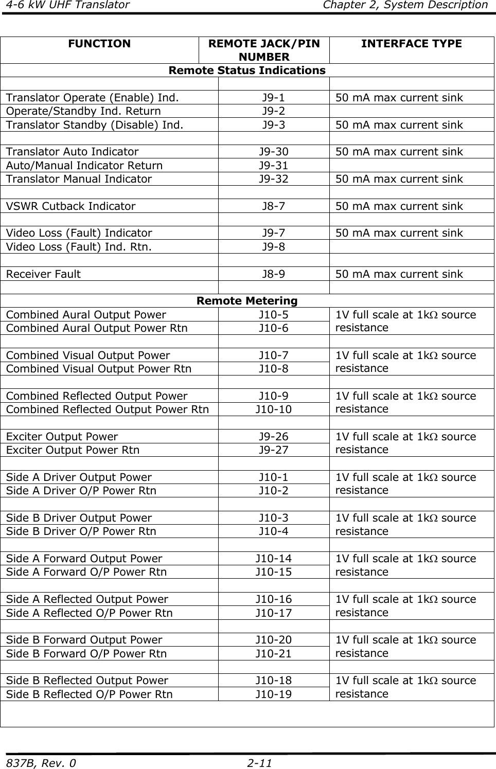
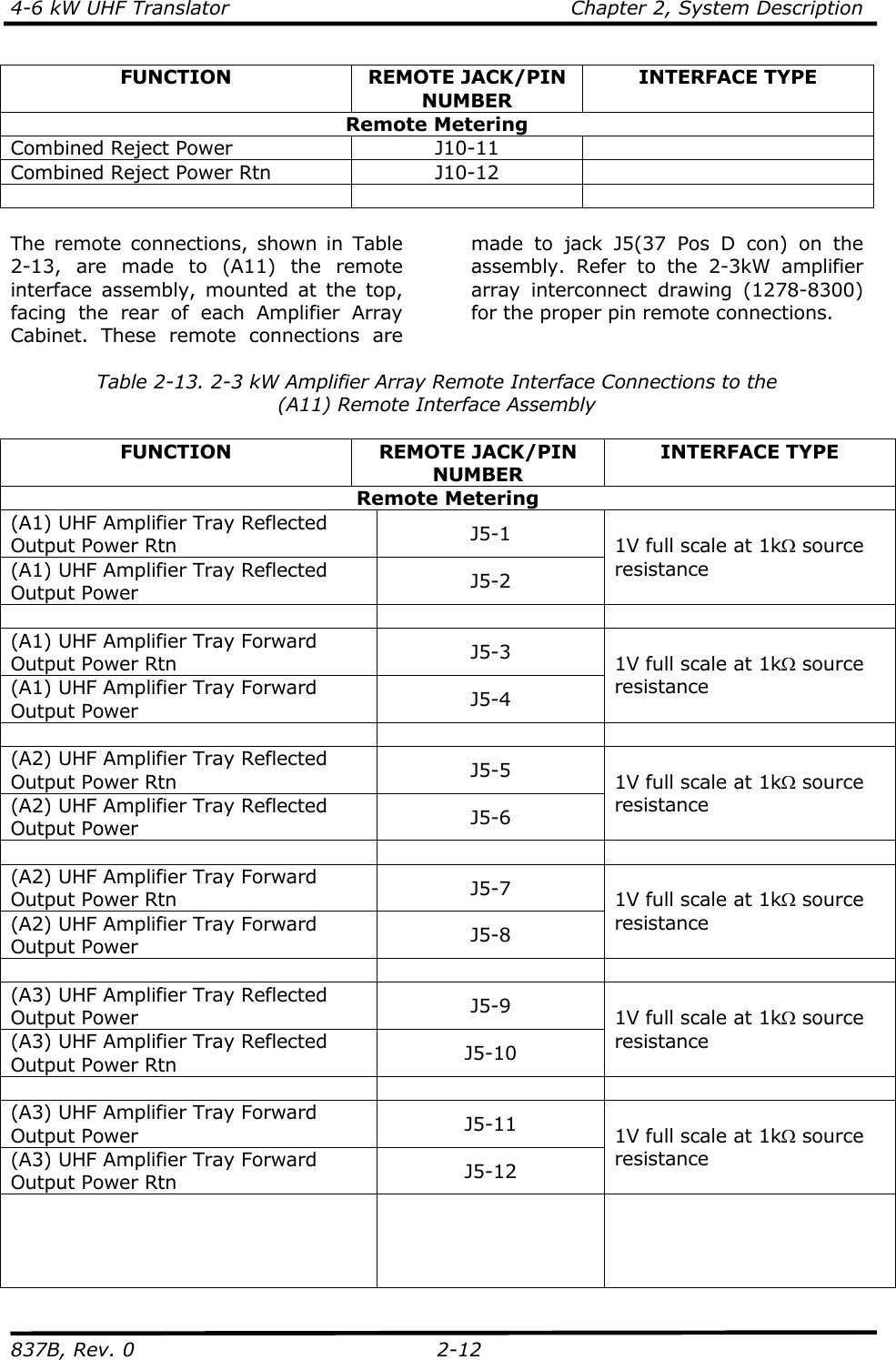
Chapter 2
5.
Chapter 3
6.
Chapter 4
7.
Chapter 5
8.
Assembly Drawings List
9.
SubAssembly Drawings List
10.
Appendix Pages
11.
Log Sheet
12.
Readings Sheet
13.
DataSheet
14.
Section 5 Users Manual Page
Chapter 2
Navigation menu
Upload a User Manual
Namespaces
Wiki Guide
HTML
PDF
Info
Views
User Manual
Discussion / Help
Navigation