UBS Axcera 837B-5 5000-Watt UHF Translator User Manual 315944
UBS-Axcera 5000-Watt UHF Translator 315944
Contents
Chapter 2
4-6 kW UHF Translator Chapter 2, System Description
837B, Rev. 0 2-1
Chapter 2
System Description
The 837B is a complete 4-6 kW UHF Solid
State Internally Diplexed Television
Translator which operates at a nominal
Visual Output Power of 4000 - 6000
Watts Peak of Sync and Average Aural
Output Power of 400 - 600 Watts, at an
A/V Ratio of 10 dB, 10 % Sound or 200 -
300 Watts at 13 dB, 5 % Sound. The
837B is made up of three Cabinets, a
UHF Single Exciter Cabinet and two
Amplifier Array Cabinets.
2.1 System Overview
The standard 837B is functionally
comprised of (A1) a Single UHF Exciter
Assembly, (A2 & A3) two 2-3 kW
Amplifier Array Assemblies, (A4) a Hybrid
Combiner Assembly and (A11) an Output
Coupler Assembly. A sample is taken
from the Hybrid Combiner and connected
to (A7) a Directional Coupler.
2.1.1 (A1) UHF Exciter Assembly
(1278-1400; Appendix C)
The (A1) UHF Exciter Assembly is made
up of the trays and assemblies listed in
Table 2-1.
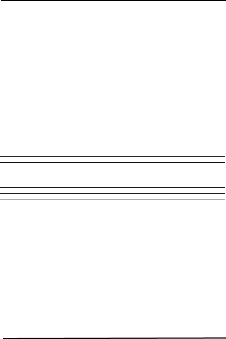
Table 2-1. UHF Exciter Assembly Trays and Assemblies
MAJOR ASSEMBLY
DESIGNATOR TRAY/ASSEMBLY NAME PART NUMBER
A1 UHF Exciter, M/N 1142458
A3 2-way splitter assembly ZSFC-2-2SMA
A4 Phase/Gain Tray 1245-1200
A5 Phase/Gain Tray 1245-1200
A6 Metering Panel 1136811
A7 UHF receiver tray 1265-1100
A8 AC Distribution Assembly 1245-1500
A9 Remote Interface Assembly 1245-1801
The UHF Exciter Tray operates using
either the IF Output from the (A7) UHF
Receiver Tray connected to J1 on the ALC
Board (1265-1305) or the Combined IF
Output generated from the (Optional)
Baseband Audio and Video Inputs
connected to J32 on the ALC Board. The
two IF Outputs are connected to the IF
Relays K3 and K4, located on the ALC
Board and by applying or removing a
Jumper on Jack J8 Pins 10 & 11 located
on (A9) the Remote Interface Assembly
(1245-1801) the IF Output is selected.
To select the output from the Modulator,
J8-10 and 11, must be connected
together. To select the output from the
Receiver Tray, J8-10 and 11, must not be
connected together.
The UHF Receiver Tray (1265-1100)
takes the received RF On Channel
Frequency and generates a 45.75 MHz +
41.25 MHz Combined IF Output. The
Combined IF Output of the Receiver Tray
connects to J6 on the rear of the (A1)
UHF Exciter that is wired to J1 on the ALC
Board. With Receiver selected, no
connection between J8-10 and 11 on the
Remote Interface Assembly, the IF
Output from the Receiver Tray connects
through the Relays to the rest of the ALC
Board.
The (Optional) Baseband Audio, from
TB1 or J3, and Video, from J1, connect
to the UHF Exciter which produces a
Combined IF Output that connects to
J32 on the ALC Board.

4-6 kW UHF Translator Chapter 2, System Description
837B, Rev. 0 2-2
To select the output from the Modulator,
J8-10 and J8-11, must be connected
together.
The Exciter RF Output of the (A1) UHF
Exciter at J15 (+10 to +20 dBm) is
connected to the S Input on (A3) the
Splitter. The Exciter Output is split two
ways by A3 with RF Output #1
connected to the input of the (A5)
Variable Phase/Gain Tray (1245-1200)
and RF Output #2 connected to the
input of the (A4) Variable Phase/Gain
Tray (1245-1200).
The Variable Phase/Gain Tray sets the
phase and gain adjustments of the RF to
provide maximum output when the
outputs of the two Amplifier Arrays are
combined. The output of the (A4)
Variable Phase/Gain Tray (+16 dBm)
connects to (A2) the Side A 2-3 kW
Amplifier Array Assembly. The output of
the (A5) Variable Phase/Gain Tray
(+16 dBm) connects to (A3) the Side B
2-3 kW Amplifier Array Assembly.
The 208/240 VAC Input to the UHF
Exciter Assembly connects to (A8) the AC
Distribution Assembly, UHF Exciter
Assembly (1245-1500) located in the
right, center rear of the Cabinet. The
Assembly contains the Terminal Block
(TB1) to which the 208/240 VAC
connects. Line 1 to TB1-1A, Line 2 to
TB1-3A and Safety Ground to TB1-2A.
The AC Distribution Assembly contains
(CB1) the Main Circuit Breaker (20
Amps) that supplies the AC to the rest of
the Single Exciter Assembly. The output
of CB1 has three MOVs, VR1, VR2 and
VR3, connected to it, VR1 from Line 1 to
ground, VR3 from Line 2 to ground and
VR2 connected across the two lines. The
AC output of CB1 is wired to A1 and A2
that are IEC Outlet Strips. The (A1)
Exciter and the (A4) Variable Phase/Gain
Tray plug into the (A1) IEC Outlet Strip.
The (A5) Variable Phase/Gain Tray, the
(A6) Metering Panel and the (A7)
Receiver Tray plug into the (A2) IEC
Outlet Strip.
When the Circuit Breaker CB1 on the
Single UHF Exciter Assembly is switched
On, +12 VDC from the Exciter is
connected to A9-TB1 in each of the
Amplifier Array Cabinets. The +12 VDC
is split 4-6 Ways on the terminal block
A9-TB1 and connected to each of the
UHF Amplifier Trays at J3-7. The +12
VDC is used for operation of the LED
Status Indicators in the UHF Amplifier
Tray. The +12 VDC is also connected to
J4-20 and then to A9-TB2 for the
(Optional) External Exhaust Kit in each
Amplifier Array. When the UHF Exciter
Tray, Translator, is switched to Operate,
an Enable is applied to each of the 2-3
kW Amplifier Arrays at J4-15 that
connects to A9-TB2. The Enable is split
4-6 Ways on the terminal block A9-TB2
and connected to each of the UHF
Amplifier Trays at J3-9. This Enable
turns on the +32 VDC Power Supply in
each Amplifier Tray. Also a Fan Enable is
connected to J4-19 and then to A9-TB2
that connects to the (Optional) External
Exhaust fan mounted on the roof of each
Amplifier Array Cabinet, turning it On.
2.1.2 (A2 & A3) 2-3 kW Amplifier
Arrays (1278-1300; Appendix C)
The (A2 & A3) 2-3-kW Amplifier Arrays
are identical and are made up of the
trays and assemblies listed in Table 2-2.

4-6 kW UHF Translator Chapter 2, System Description
837B, Rev. 0 2-3
Table 2-2. Amplifier Array Trays and Assemblies
MAJOR ASSEMBLY
DESIGNATOR TRAY/ASSEMBLY NAME PART NUMBER
A1, A2, A3, A4, A5(5kW) &
A6(6kW) UHF Amplifier Trays, LDMOS
(Low Band) 1301560,
(Mid Band) 1301561,
Or (High Band) 1301562
A7 4, 5 or 6 Way Combiner Various
A8 Output Coupler Assembly 1016-1043
A12 Reject Load Assembly 1278-1312
A9-A1 8-Way Splitter 1245-1701 (ZFSC-8-43)
A10 AC Distribution Assembly Three Phase 1278-1100
Or Single Phase 1278-1200
A11 Interface Assembly 1131532
The (A2 & A3) Amplifier Array Assemblies
each contain (A9-A1) an 8 Way Splitter
(ZFSC-8-43), four, five or six {A1, A2,
A3, A4, A5(5kW) & A6(6kW)} UHF
Amplifier Trays, LDMOS, (A7) a 4, 5 or 6
Way Combiner, (A12) a Reject Load
Assembly, (A8) an Output Coupler and
(A10) an AC Distribution Assembly, Three
Phase (1278-1100) or Single Phase
(1276-1200). The reject output from the
Combiner connects to (A12) a Reject
Load Assembly, which contains (A12-A2)
a Combiner Reject Load Board (1278-
1311) in a 5 or 6 kW configuration.
The RF Input (+16 dBm) from the
Variable Phase/Gain Tray connects to J1
on (A11) the Interface Panel located in
the Amplifier Array Assembly. The RF is
connected to the COM Input of (A9-A1)
the 8 Way Splitter that splits it eight
ways. The outputs (+6 dBm) connected
to J1, the RF Input Jack on each of the
UHF Amplifier Trays or are terminated
with 50Ω. Each of the UHF Amplifier
Trays amplify the RF signals to the power
needed to produce the total output power
for the Translator, with a maximum of
600 Watts per Tray. The outputs (+57.5
to +60 dBm) of the UHF Amplifier Trays,
LDMOS are combined in the (A7) 4, 5 or
6 Way Combiner assembly. The output
of the combiner is cabled to (A8) the
Output Coupler Assembly that supplies a
Forward and a Reflected Power Sample of
the output from the Amplifier Assembly
to the Metering Panel in the Single
Exciter Assembly. The reject output of
the Combiner, in a 5kW or 6kW
configuration, connects to (A12) the
Reject Load Assembly that dissipates any
reject due to miss-tuning or a
malfunction in any of the Amplifier Trays.
The RF Output of the Coupler at J2
(+63.5 to +65.2 dBm) is the RF output
of the 2-3 kW Amplifier Array.
In each UHF Amplifier Tray, a Forward
Power Sample and a Reflected Power
Sample, from the Combiner Board, are
connected to the Dual Peak Detector
Board, Single Supply. The Dual Peak
Detector provides peak detected forward
samples to the Amplifier Control Board
that supplies the samples to the front
panel meter of the UHF Amplifier Tray.
Before exiting each UHF Amplifier Tray
the RF is fed through a Circulator for
protection of the Tray from high VSWR
conditions. The Reject Port of the
Circulator provides a Reject Sample to
the Combiner Board which supplies the
Reflected Sample to the Dual Peak
Detector Board, Single Supply located in
the Tray that connects to the front panel
meter for monitoring purposes.
The 208/240 VAC Input to each Amplifier
Array Assembly connects to (A10) the AC
Distribution Assembly located on the
right side, center rear of the Cabinet.
The Assembly contains the Terminal
Block (TB1) to which the 208/240 Three
Phase or Single phase connects.

4-6 kW UHF Translator Chapter 2, System Description
837B, Rev. 0 2-4
Three phase connects, Line 1 to TB1-1A,
Line 2 to TB1-2A, Line 3 to TB1-3A and
Safety Ground to TB1-4A.
Single phase connects, Line 1 to TB1-1A,
Line 2 to TB1-3A and Safety Ground to
TB1-4A.
The AC Distribution Panel contains nine
Circuit Breakers that supply the AC to the
rest of the Amplifier Assembly. The
Input AC from TB1B is connected to
(CB1) the Main AC Circuit Breaker (55
Amps three phase or 100 Amps single
phase) that distributes the 208/240 VAC
to the other eight circuit breakers. The
output of CB1 has three MOVs, VR4 from
Line 1 to ground, VR6 from Line 2 to
Ground and VR3 connected across the
two lines for surge and over-voltage
protection. The switched Input AC is
wired through the Circuit Breakers, CB2-
CB7, via AC Line Cords to the six UHF
Amplifier Trays, LDMOS mounted in each
Amplifier Array Cabinet. CB2 is a 20
Amp Circuit Breaker that supplies the AC
voltage to the (A1) UHF Amplifier Tray.
CB3 is a 20 Amp Circuit Breaker that
supplies the AC voltage to the (A2) UHF
Amplifier Tray. CB4 is a 20 Amp Circuit
Breaker that supplies the AC voltage to
the (A3) UHF Amplifier Tray. CB5 is a 20
Amp Circuit Breaker that supplies the AC
voltage to the (A4) UHF Amplifier Tray.
In a 5kW configuration, CB6 is a 20 Amp
Circuit Breaker that supplies the AC
voltage to the (A5) UHF Amplifier Tray.
In a 6 kW configuration, CB7 is a 20 Amp
Circuit Breaker that supplies the AC
voltage to the (A6) UHF Amplifier Tray.
In 5 and 6 kW configurations, CB8 and
CB9 are 3 Amp Circuit Breakers that
supply AC to the two cooling fans
mounted in the Reject Load Assembly in
the Amplifier Array Assembly.
2.1.2.1 (A13) (Optional) External
Exhaust Kit (1061320)
Each of the 2-3 kW Amplifier Array
Assemblies may contain the (Optional)
(A13) External Exhaust Kit mounted on
the roof of the cabinets. This kit provides
greater cooling by venting the hot air
outside the Translator room using a
blower fan. +12 VDC is applied to TB1-
4A in the Exhaust enclosure when the
UHF Exciter circuit breaker is switched
On. An Enable is connected to TB1-3A
when the UHF Exciter, Translator, is
switched to Operate. The Enable
energizes the Isolation Relay that applies
the 120 VAC to the fan that will operate.
2.1.3 Translator Output Assemblies
The outputs of the (A2 & A3) 2-3 kW
Amplifier Assemblies (+63.5 to +65.2
dBm) connect through (A5 or A6) 1-5/8”
to 3-1/8” Adapters to (A4) a Hybrid
Combiner. The combiner combines the
output from each Amplifier Assembly into
a single output. The Reject Output of the
Hybrid Combiner is connected through
(A12) a 1-5/8” to 3-1/8” Adapter to (A7)
a Directional Coupler (1016-1043) that
provides a Reject Sample from J3 to the
Metering Panel located in the UHF Exciter
Assembly for monitoring purposes. The
output of the Directional Coupler
connects to (A8) a 2500 Watt Reject
Load which dissipates any reject due to
problems in one of the Amplifier Arrays.
Mounted on the 2500 Watt Load is (A8-
A1) a Thermal Switch that connects to
the Overtemperature Fault circuit located
on the Transmitter Control Board in the
UHF Exciter Tray. If the temperature of
the load reaches 155°F. the switch closes
and causes an Overtemperature Fault to
occur which shuts down the Translator.
The output of the Hybrid Combiner at J3
is fed through 3-1/8” hard line to (A9) a
Bandpass Filter, (A10) an Output Trap
Filter Assembly, then to (A11) the Output
Coupler Assembly and finally to the
Antenna for your System. The Bandpass
Filter and Trap Filter are tuned to provide
high out of band rejection of unwanted
generated products. The filtered signal is
connected to (A11) an Output Coupler
Assembly that provides a Combined
Forward and a Combined Reflected Power

4-6 kW UHF Translator Chapter 2, System Description
837B, Rev. 0 2-5
Sample to the Metering Panel located in
the Single UHF Exciter Assembly. The
Forward Sample is processed to provide
peak detected Visual and Aural Power
Output Samples to the front panel Meter
of the Metering Panel. The Reflected
Power Sample is also peak detected and
wired to the front panel Meter. A Sample
of the RF Output, for test purposes can
be taken from J5 on the Coupler, but a
20 dB Attenuator must be connected to
J6 for the Sample port to operate. An
appropriate attenuator must be
connected to J5 to protect any test
equipment connected to it.
2.2 Control and Status
The Control and Status of the Translator
are provided by the Meter indications on
the Metering Panel and the Variable
Phase/Gain Trays. There are also
Control, Status and LED Indications
located on the front panel of the UHF
Exciter Tray.
The switches and LED indicators, which
are mounted so that the switches and
LEDs are operated or viewed from the
front Panel of the UHF Exciter, are part of
the Transmitter Control Board
(1061195). On the UHF Exciter Tray,
switch (S1) is an Operate/Standby
Switch that provides the Operate
Command (Enable), when in Operate, to
the each of the Amplifier Arrays. The
Enable to each Amplifier Array Assembly
at J4-15 & 16 is split 4, 5 or 6 ways on
the terminal block A9-TB2, which are
then applied to each of the UHF Amplifier
Trays at J3-9. The Enable is needed to
turn on the Switching Power Supplies
located in each of the UHF Amplifier
Trays.
When the UHF Exciter is in Operate, the
Green LED (DS2) is On and when in
Standby the Amber LED (DS1) is On.
Note: If the Translator does not switch
to Operate when S1 is switched to
Operate, check that a dummy plug, with
a Jumper between Pins 1 & 2, is
connected to Jack J7 located on (A9) the
Remote Interface Assembly in the UHF
Exciter Assembly. This Jumper provides
the Interlock needed for the operation of
the Translator. If the Interlock is
present, the Green LED (DS5), located on
the Transmitter Control Board, should be
lit.
Operation of the Translator is controlled
by the front panel switches located on
the UHF Exciter Tray. During Normal
operation of the Translator, Switch S2
should be in the Auto position. The front
panel of the UHF Exciter also has LEDs
that indicate a Video Fault (Loss), Red
LED (DS9) and a VSWR Cutback, Amber
LED (DS7).

4-6 kW UHF Translator Chapter 2, System Description
837B, Rev. 0 2-6
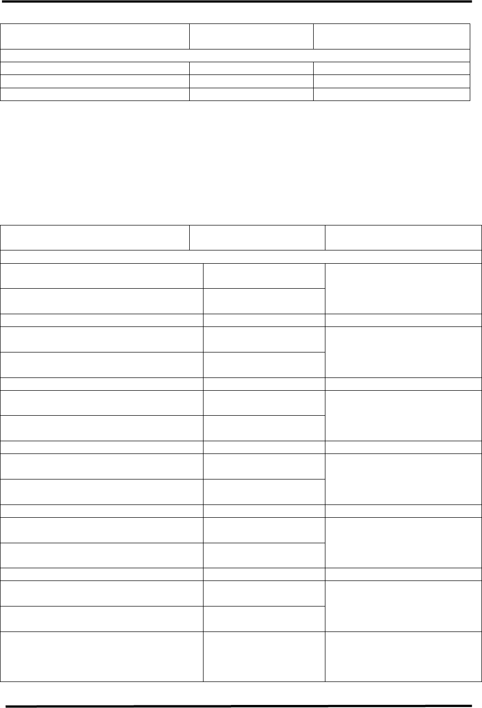
2.2.1 (A1) UHF Exciter Tray (1142458; Appendix C)
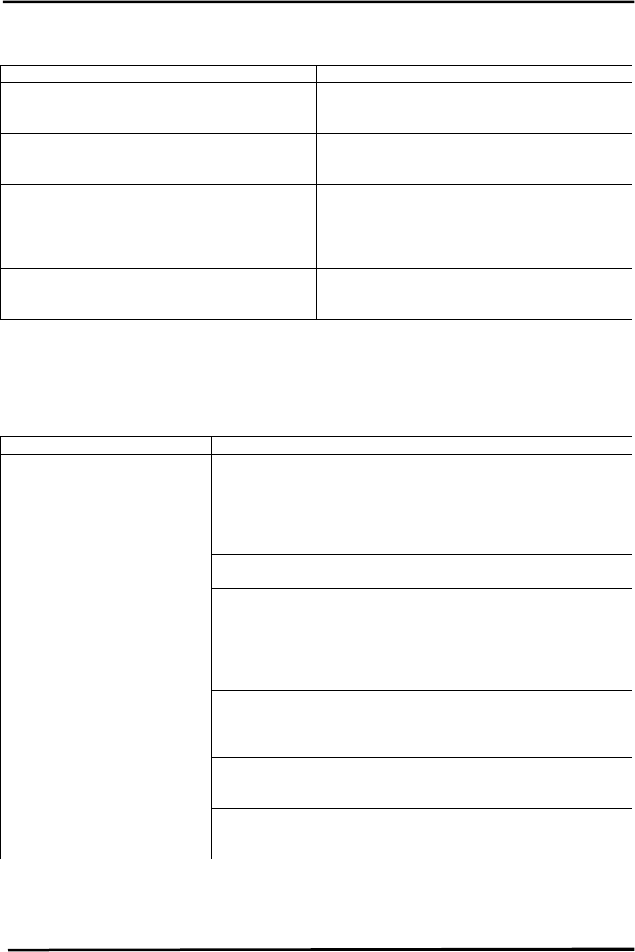
Table 2-3. UHF Exciter Tray Meters
METER FUNCTION
This meter reads power in terms of a percentage of the
calibrated output power level on the upper scale. The
voltage level or frequency level is read on one of the bottom
two scales. A full-scale reading on the top scale is 120%.
The meter also reads % Aural Power, % Exciter Power,
% Reflected Power, audio levels, video levels and the
ALC voltage.
With Switch S3 in
Position Display
Switch S3, Meter
Selects the desired ALC voltage
reading, % Exciter Power, %
Reflected Power, % Visual
Power, % Aural Power, video
level, or audio level
Audio
(0 to 100 kHz)
Reads the audio level, ±25 kHz
balanced or ±75 kH composite,
on the 0 to 10 scale. Will
indicate baseband audio, if it is
connected to the Translator,
even with the video +4.5-MHz
SCA input selected.
ALC
(0 to 10 volts)
Reads the ALC voltage level, .8
VDC, on the 0 to 10 scale (full
scale=1 volt)
% Exciter
(0 to 100)
Reads the % Exciter Output
Power Level needed to attain
100% output of the Translator
on the top scale
% Aural Power
(0 to 100)
Reads the % Aural Output
Power of the Translator,
100%= watts for 10 dB
A/V ratio, on the top scale
% Visual Power
(0 to 100)
Reads the % Visual Output
Power of the Translator,
100%= watts peak of
sync, on the top scale
% Reflected
(0 to 100)
Reads the % Reflected Output
Power, <5%, on the top scale
Meter (A1-A18)
Video
(0 to 100 IRE)
Reads the video level, 1 volt
at peak white, on the 0 to 10
scale

4-6 kW UHF Translator Chapter 2, System Description
837B, Rev. 0 2-7
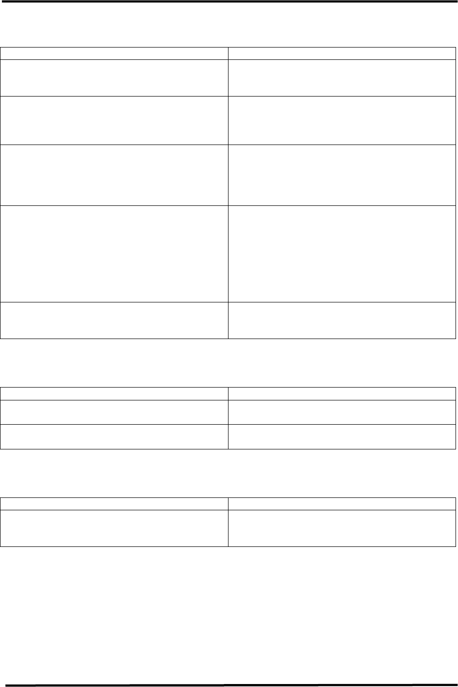
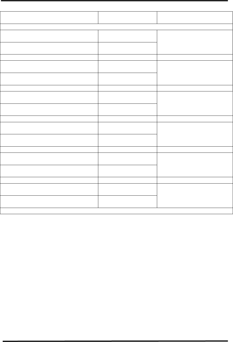
Table 2-4. UHF Exciter Tray Switches
SWITCH FUNCTION
Translator S1
Operate/Standby
The momentary switch S1 applies a ground
to K1, a latching relay on the transmitter
control board. K1 will switch either to
Operate or to Standby depending on which
direction S1 is pushed. When switched to
Operate, the low, enable commands are
applied to the UHF amplifier trays. These
enables will turn on the UHF amplifier trays.
The opposite occurs when the switch is
turned to Standby.
Mode Select S2
Auto/Manual
The momentary switch S2 applies a ground
to K2, a latching relay on the transmitter
control board. K2 will switch the Translator
to Automatic or Manual depending on which
direction S2 is pushed. In Automatic, the
video fault command from the ALC board
will control the operation of the Translator.
The Translator will switch to Standby, after
a slight delay, if the input video is lost and
will switch back to Operate, quickly, when
the video is restored. In Manual, the
Translator is controlled by the operator
using the front panel Operate/Standby
switch or by remote control.
Power Adjust R1
The 5-kΩ pot A20 sets the ALC level on the
ALC board to set the output power of the
translator.
Table 2-5. UHF Exciter Tray Fault Indicators
INDICATOR DESCRIPTION
Video Loss (DS9 Red)
Indicates that the input video to the
translator has been lost. The fault is
generated on the ALC board in the UHF
exciter tray.
VSWR Cutback (DS7 Amber)
Indicates that the reflected power level of
the translator has increased above 20%;
this automatically cuts back the output
power level to 20%. The fault is generated
on the transmitter control board in the UHF
exciter tray.
4-6 kW UHF Translator Chapter 2, System Description
837B, Rev. 0 2-8
Table 2-6. UHF Exciter Tray Samples
SAMPLE DESCRIPTION
f(IF)
A sample of the visual IF that is taken from
the sample jack on the IF carrier oven
oscillator board
f(IC)
A sample of the intercarrier signal that is
taken from the sample jack on the aural IF
synthesizer board
f(s)
A sample of the channel oscillator output
that is taken from the sample jack of the
channel oscillator assembly
Exciter O/P An output power sample of the exciter that
is taken from the UHF upconverter board
Translator O/P
A forward power sample of the translator
that is taken from the visual/aural metering
board
2.2.2 {A1, A2, A3, A4, A5(5kW) & A6(6kW} UHF Amplifier Trays, LDMOS
(1301560, low band/1301561, mid band/1301562, high band; Appendix C)
Table 2-7. UHF Amplifier Tray, LDMOS Meters
METER FUNCTION
This meter reads power in terms of a percent of the
calibrated power output value. A full-scale reading is
100%, which is equivalent to the full-rated 600 watts peak
of sync visual + aural output power. The meter also reads
the % Reflected Power, power supply voltage levels, and
AGC voltage levels.
With Switch S2 in
Position Display
Switch S2, Meter Selects the desired % power
or the voltage reading
% Output Pwr
Reads the % Output Power of
the tray (100%=600 watts
peak of sync visual + aural)
on the top scale
% Refl (Reflected)
Reads the % Reflected Output
Power of the tray (<10% with
all amplifier trays operating)
as measured on the top scale
Power Supply
Reads the power supply
voltage >+30 VDC(+32 VDC)
on the middle scale
Meter (A1 thru A6 - A9)
AGC Voltage
Reads the AGC voltage level
(+1 VDC to +3 VDC) on the
bottom scale
4-6 kW UHF Translator Chapter 2, System Description
837B, Rev. 0 2-9
Table 2-8. UHF Amplifier Tray, LDMOS Status Indicators
INDICATOR DESCRIPTION
Enable (DS4 Green)
Indicates that an enable, Operate
command, is applied to the UHF amplifier
tray from the UHF exciter tray
Overdrive (DS2 Red)
Indicates that the level of the drive is too
high and the protection circuit will limit the
drive to the set threshold. This fault is
generated on the amplifier control board.
VSWR Cutback (DS1 Red)
Indicates that the reflected power level of
the tray has increased above 50% and the
output power level will automatically be cut
back to 20%. This fault is generated on the
amplifier control board.
Overtemp (DS3 Red)
Indicates that the temperature of (A5-A6-
A3 and A5-A6-A4), one or both of the two
thermal switches mounted on the heatsink
assembly for the output amplifiers, is above
175° F. When this fault occurs, the Enable
to the switching power supply in the
affected amplifier tray is removed
immediately and the tray will shut down.
Input Fault (DS5 Red)
Indicates that the input RF level to the
amplifier trays has dropped below the
0 dBm range
Table 2-9. UHF Amplifier Tray, LDMOS Control Adjustments
ADJUSTMENT DESCRIPTION
Phase (A10-R5) Adjusts the phase of the RF output by
approximately 70%
Gain (A11-R6) Adjusts the gain of the RF output when the
amplifier control board is in the AGC mode
Table 2-10. UHF Amplifier Tray, LDMOS Sample
SAMPLE DESCRIPTION
Module O/P (0 dBm)
A sample of the combined output of the
four dual-stage amplifier boards that is
taken from the dual peak detector board
2.3 Input and Remote Connections
The Baseband Video and Audio Inputs to
the Translator, connect to the (A9)
Remote Interface Panel located on the
rear of the UHF Exciter Assembly. The
Baseband Video Input connects to Jack
J2, which is loop-thru connected to J1,
that is wired to J1 on the Exciter. The
Baseband Audio Input connects to
Terminal Block TB1 for Balanced Audio or
to Jack J6, which is loop-thru connected
to J13, that is wired to J3 on the Exciter,
for Composite, Stereo, Audio.
4-6 kW UHF Translator Chapter 2, System Description
837B, Rev. 0 2-10
Remote Monitoring and Operation of the
Translator is provided through the Jacks
(J8, J9 & J10) located on (A9) the
Remote Interface Assembly located on
the rear of the UHF Exciter Assembly.
Jack (J7) should have a dummy plug
connected to it, which has a jumper
connected between Pins 1 & 2, that
provides the Interlock to the Exciter
needed to operate the Translator. If the
Jumper is missing, the Translator will not
switch to Operate. If remote connections
are made to the Translator they should
be made through the plugs provided in
the Installation Material as noted on the
Interconnect Drawing (1278-8400) for
the Single UHF Exciter.
The On Channel RF Input to the Receiver
Tray connects to the Translator through
(A9) the Remote Interface Assembly at
J1, "N" type connector, for 50Ω Input or
J3, "F" type connector, for 75Ω Input.
The remote connections, listed in Table
2-11, are made to the (A9) A/V input and
remote interface assembly mounted at
the top, facing the rear of the UHF
Exciter Cabinet. The remote connections
are made to jacks J7(9 Pos D con), J8(25
Pos D con), J9(37 Pos D con) and J10(25
Pos D con) on the assembly. Refer to the
exciter interconnect drawing (1278-
8400) for the proper pin remote
connections.
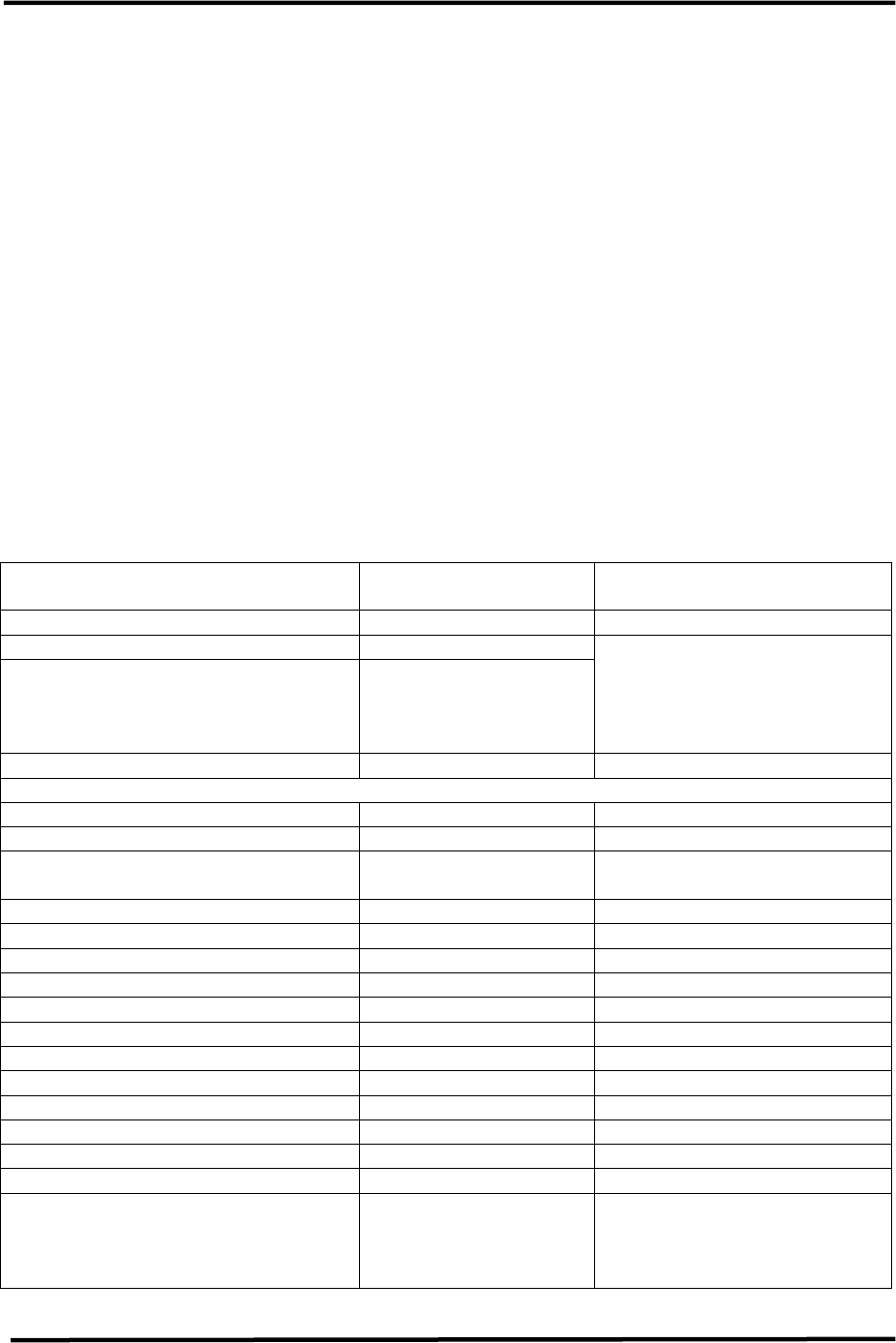
Table 2-11. UHF Exciter Remote Interface Connections to the
(A9) A/V Input and Remote Interface Assembly
FUNCTION REMOTE JACK/PIN
NUMBER
INTERFACE TYPE
Translator Enable Interlock J7-1
Translator Enable Interlock Rtn. J7-1
J7-1 and J7-2 must be
jumpered together for
normal operation. The
(1176-1038) jumper jack
should be in place.
Remote Control Commands
Translator Standby (Disable) J8-1 Contact closure
Translator Standby/Operate Rtn.
J8-2
Translator Operate (Enable) J8-3 Contact closure
Translator Manual J8-4 Contact closure
Translator Auto/Manual Rtn. J8-5
Translator Auto J8-6 Contact closure
Power Level Lower (Optional) J9-4 Contact closure
Pwr Lvl Raise/Lower Rtn (Optional) J9-5
Power Level Raise (Optional) J9-6 Contact closure
Modulator Select (Optional) J8-10 Contact closure
Modulator Select Rtn (Optional) J8-11

4-6 kW UHF Translator Chapter 2, System Description
837B, Rev. 0 2-11
FUNCTION REMOTE JACK/PIN
NUMBER
INTERFACE TYPE
Remote Status Indications
Translator Operate (Enable) Ind. J9-1 50 mA max current sink
Operate/Standby Ind. Return J9-2
Translator Standby (Disable) Ind. J9-3 50 mA max current sink
Translator Auto Indicator J9-30 50 mA max current sink
Auto/Manual Indicator Return J9-31
Translator Manual Indicator J9-32 50 mA max current sink
VSWR Cutback Indicator J8-7 50 mA max current sink
Video Loss (Fault) Indicator J9-7 50 mA max current sink
Video Loss (Fault) Ind. Rtn. J9-8
Receiver Fault J8-9 50 mA max current sink
Remote Metering
Combined Aural Output Power J10-5
Combined Aural Output Power Rtn J10-6
1V full scale at 1kΩ source
resistance
Combined Visual Output Power J10-7
Combined Visual Output Power Rtn J10-8
1V full scale at 1kΩ source
resistance
Combined Reflected Output Power J10-9
Combined Reflected Output Power Rtn J10-10
1V full scale at 1kΩ source
resistance
Exciter Output Power J9-26
Exciter Output Power Rtn J9-27
1V full scale at 1kΩ source
resistance
Side A Driver Output Power J10-1
Side A Driver O/P Power Rtn J10-2
1V full scale at 1kΩ source
resistance
Side B Driver Output Power J10-3
Side B Driver O/P Power Rtn J10-4
1V full scale at 1kΩ source
resistance
Side A Forward Output Power J10-14
Side A Forward O/P Power Rtn J10-15
1V full scale at 1kΩ source
resistance
Side A Reflected Output Power J10-16
Side A Reflected O/P Power Rtn J10-17
1V full scale at 1kΩ source
resistance
Side B Forward Output Power J10-20
Side B Forward O/P Power Rtn J10-21
1V full scale at 1kΩ source
resistance
Side B Reflected Output Power J10-18
Side B Reflected O/P Power Rtn J10-19
1V full scale at 1kΩ source
resistance
4-6 kW UHF Translator Chapter 2, System Description
837B, Rev. 0 2-12
FUNCTION REMOTE JACK/PIN
NUMBER
INTERFACE TYPE
Remote Metering
Combined Reject Power J10-11
Combined Reject Power Rtn J10-12
The remote connections, shown in Table
2-13, are made to (A11) the remote
interface assembly, mounted at the top,
facing the rear of each Amplifier Array
Cabinet. These remote connections are
made to jack J5(37 Pos D con) on the
assembly. Refer to the 2-3kW amplifier
array interconnect drawing (1278-8300)
for the proper pin remote connections.
Table 2-13. 2-3 kW Amplifier Array Remote Interface Connections to the
(A11) Remote Interface Assembly
FUNCTION REMOTE JACK/PIN
NUMBER
INTERFACE TYPE
Remote Metering
(A1) UHF Amplifier Tray Reflected
Output Power Rtn J5-1
(A1) UHF Amplifier Tray Reflected
Output Power J5-2
1V full scale at 1kΩ source
resistance
(A1) UHF Amplifier Tray Forward
Output Power Rtn J5-3
(A1) UHF Amplifier Tray Forward
Output Power J5-4
1V full scale at 1kΩ source
resistance
(A2) UHF Amplifier Tray Reflected
Output Power Rtn J5-5
(A2) UHF Amplifier Tray Reflected
Output Power J5-6
1V full scale at 1kΩ source
resistance
(A2) UHF Amplifier Tray Forward
Output Power Rtn J5-7
(A2) UHF Amplifier Tray Forward
Output Power J5-8
1V full scale at 1kΩ source
resistance
(A3) UHF Amplifier Tray Reflected
Output Power J5-9
(A3) UHF Amplifier Tray Reflected
Output Power Rtn J5-10
1V full scale at 1kΩ source
resistance
(A3) UHF Amplifier Tray Forward
Output Power J5-11
(A3) UHF Amplifier Tray Forward
Output Power Rtn J5-12
1V full scale at 1kΩ source
resistance
4-6 kW UHF Translator Chapter 2, System Description
837B, Rev. 0 2-13
FUNCTION REMOTE JACK/PIN
NUMBER INTERFACE TYPE
Remote Metering
(A4) UHF Amplifier Tray Forward
Output Power J5-13
(A4) UHF Amplifier Tray Forward
Output Power Rtn J5-14
1V full scale at 1kΩ source
resistance
(A4) UHF Amplifier Tray Reflected
Output Power J5-15
(A4) UHF Amplifier Tray Reflected
Output Power Rtn J5-16
1V full scale at 1kΩ source
resistance
(A5) UHF Amplifier Tray Forward
Output Power (5kW configuration) J5-18
(A5) UHF Amplifier Tray Forward
Output Power Rtn(5kW configuration) J5-17
1V full scale at 1kΩ source
resistance
(A5) UHF Amplifier Tray Reflected
Output Power(5kW configuration) J5-21
(A5) UHF Amplifier Tray Reflected
Output Power Rtn(5kW configuration) J5-20
1V full scale at 1kΩ source
resistance
(A6) UHF Amplifier Tray Forward
Output Power(6kW configuration) J5-22
(A6) UHF Amplifier Tray Forward
Output Power Rtn(6kW configuration) J5-23
1V full scale at 1kΩ source
resistance
(A6) UHF Amplifier Tray Reflected
Output Power(6kW configuration) J5-24
(A6) UHF Amplifier Tray Reflected
Output Power Rtn(6kW configuration) J5-25
1V full scale at 1kΩ source
resistance
2.4 Main AC Input
The Translator needs an AC input of
208/240 VAC @ 55 Amps Three Phase or
100 Amps Single Phase for each Amplifier
Array Assembly and 208/240 VAC @ 20
Amps Single Phase for the UHF Exciter
Assembly.
These AC Inputs connect to the AC
Distribution Assemblies located facing
toward the rear in the middle, right side
of each of the cabinets.