UBS Axcera CL1TC-4 400-Watt, 1.6 GHz DVB-H Transmitter User Manual 8SC Transmitter
UBS-Axcera 400-Watt, 1.6 GHz DVB-H Transmitter 8SC Transmitter
Contents
- 1. User Manual Part 1
- 2. User Manual Part 2
User Manual Part 1

NOTE: This equipment has been tested and found to comply with the limits for a Class A
digital device, pursuant to part 15 of the FCC Rules. These limits are designed to pro-vide
reasonable protection against harmful interference when the equipment is operated in a
commercial environment. This equipment generates, uses, and can radiate radio frequency
energy and, if not installed and used in accordance with the instruction manual, may cause
harmful interference to radio communications. Operation of this equipment in a residential
area is likely to cause harmful interference in which case the user will be required to correct
the interference at his own expense.
RESTRICTIONS ON USE, DUPLICATION OR DISCLOSURE
OF PROPRIETARY INFORMATION
This document contains information proprietary to UBS-Axcera, to its affiliates or to a third party to which UBS-
Axcera may have a legal obligation to protect such information from unauthorized disclosure, use or duplication.
Any disclosure, use or duplication of this document or any of the information herein for other than the specific
purpose for which it was disclosed by UBS-Axcera is expressly prohibited, except as UBS-Axcera may otherwise
agree in writing. Recipient by accepting this document agrees to the above stated conditional use of this document
and this information disclosed herein.
Copyright © 2012, UBS-Axcera

CL1TC-4 400W DVB-H Transmitter Table of Contents
Product Manual, Rev. 1 i 7/30/13
Table of Contents
1. Introduction .................................................................................................... 1
1.1 Manual Overview ........................................................................................ 1
1.2 Safety ....................................................................................................... 1
1.3 Contact Information .................................................................................... 2
1.4 Return Material Procedure ............................................................................ 2
1.5 Limited One Year Warranty for Axcera Products............................................... 3
1.6 Warning .................................................................................................... 4
1.7 Emergency First Aid Instructions ................................................................... 5
1.8 Abbreviations/Acronyms .............................................................................. 6
2 Product Description ......................................................................................... 7
2.1 Product Overview........................................................................................ 7
2.2 Cabinet Tour .............................................................................................. 9
2.3 Product Architecture.................................................................................. 13
2.3.1 Transmitter Overview ..........................................................................13
2.3.2 UPS...................................................................................................13
2.3.3 Playout Server ....................................................................................13
2.3.4 Modulator ..........................................................................................15
2.3.4.1 DVB-H Modulator......................................................................... 15
2.3.4.2 Amplifier .................................................................................... 15
2.3.4.3 Bandpass Filter............................................................................ 16
2.3.4.4 GPS Receiver .............................................................................. 16
2.3.4.5 I/O Extension Board..................................................................... 16
2.3.4.6 Transmitter Controller Module ....................................................... 16
2.3.5 High Power Amplifier (HPA) ..................................................................18
2.3.5.1 HPA Enhanced Features and Design Concepts .................................. 20
2.3.5.2 HPA Controller............................................................................. 20
2.4 Breaker Panels ......................................................................................... 21
2.5 Control Interfaces ..................................................................................... 21
2.6 Remote Upgrades ..................................................................................... 22
3 Transmitter Technical Specifications ............................................................. 23
3.1 Modulation Standard ................................................................................. 23
3.2 Modulator Control Interfaces ...................................................................... 23
3.3 Modulator Inputs ...................................................................................... 23
3.4 Modulator Monitoring Outputs..................................................................... 24
3.5 Modulator RF............................................................................................ 24
3.6 HPA Control Interfaces .............................................................................. 25
3.7 HPA RF Input ........................................................................................... 25
3.8 HPA/Transmitter RF Output ........................................................................ 25
3.9 Modulator Digital Pre-Correction ................................................................. 26
3.10 GPS ........................................................................................................ 27
3.11 Power Supply ........................................................................................... 28
3.11.1 Modulator ..........................................................................................28
3.11.2 HPA...................................................................................................28
3.12 Environmental .......................................................................................... 28
3.13 Mechanical............................................................................................... 28
3.13.1 Modulator ..........................................................................................28
3.13.2 HPA...................................................................................................28
4 Installation.................................................................................................... 29
4.1 Unpacking and Inspection .......................................................................... 29
4.2 Installation Safety..................................................................................... 29
4.3 Installation Overview................................................................................. 29
4.4 Cabinet Installation ................................................................................... 30

CL1TC-4 400W DVB-H Transmitter Table of Contents
Product Manual, Rev. 1 ii 7/30/13
4.4.1 Installation Surface .............................................................................30
4.4.2 Cabinet Positioning..............................................................................30
4.5 Mains AC Power........................................................................................ 30
4.5.1 General..............................................................................................30
4.5.2 Electrical Safety ..................................................................................31
4.5.3 Cabinet Wiring....................................................................................31
4.5.3.1 Cabinet Grounding ....................................................................... 31
4.5.3.2 Mains AC Power Cable .................................................................. 31
4.6 Breaker Panels ......................................................................................... 32
4.6.1 Breaker Panel 1 ..................................................................................32
4.6.2 Breaker Panel 2 ..................................................................................33
4.7 Cabinet Sub-Assemblies............................................................................. 34
4.7.1 Modulator Installation ..........................................................................34
4.7.1.1 RS232 Serial Port ........................................................................ 34
4.7.1.2 I/O Serial Port............................................................................. 35
4.7.1.3 RS485 Serial Port ........................................................................ 35
4.7.2 HPA Installation ..................................................................................36
4.7.2.1 Serial Port .................................................................................. 36
5 Commissioning and Operation ....................................................................... 37
5.1 Introduction ............................................................................................. 37
5.2 Installation Verification .............................................................................. 37
5.3 Initial On-Site Turn-on Procedure................................................................ 37
5.3.1 Transmitter AC Power-up Procedure.......................................................37
5.3.2 Configuring the Transmitter..................................................................38
5.3.2.1 Configuring the Network Parameters .............................................. 38
5.3.2.2 Configuring the Input Parameters .................................................. 40
5.3.2.3 Configuring the Modulation Parameters ........................................... 40
5.3.3 Turning On the RF Output.....................................................................42
5.3.4 Turning Off the RF Output ....................................................................42
5.4 Control and Communication ....................................................................... 43
5.4.1 Control and Communication Interfaces ...................................................43
5.4.2 Local Access.......................................................................................43
5.4.3 Remote Access ...................................................................................43
5.5 Modes of Operation ................................................................................... 43
5.5.1 Transmitter Operating Modes................................................................43
5.5.1.1 Broadcast Mode........................................................................... 44
5.5.1.2 Standby Mode ............................................................................. 44
5.5.2 Modulator Operating Modes ..................................................................44
5.6 Indicators and Controls.............................................................................. 44
5.6.1 Modulator ..........................................................................................45
5.6.1.1 Front Panel ................................................................................. 45
5.6.2 HPA...................................................................................................46
5.6.2.1 Front Panel ................................................................................. 46
5.6.2.2 Rear Panel .................................................................................. 48
6 Web GUI Interface ........................................................................................ 49
6.1 Introduction ............................................................................................. 49
6.2 Access and Navigation ............................................................................... 49
6.2.1 Login.................................................................................................49
6.2.2 Global Status Page ..............................................................................50
6.2.3 GUI Navigation and Structure ...............................................................51
6.2.4 Changing Parameters...........................................................................52
6.3 Status Menu............................................................................................. 52
6.3.1 Global Status......................................................................................53
6.3.2 GPS Status.........................................................................................56

CL1TC-4 400W DVB-H Transmitter Table of Contents
Product Manual, Rev. 1 iii 7/30/13
6.3.3 HPA...................................................................................................57
6.4 Config Menu............................................................................................. 58
6.4.1 Modulator Mode ..................................................................................59
6.4.2 Transmission ......................................................................................60
6.4.3 Input.................................................................................................64
6.4.4 Output...............................................................................................66
6.4.5 RF Channels .......................................................................................68
6.4.6 User RF Channels................................................................................68
6.4.7 Non-Linear Pre-corrector ......................................................................69
6.4.8 Linear Pre-corrector.............................................................................69
6.4.9 HPA Control........................................................................................70
6.4.10 GPS...................................................................................................71
6.4.11 Site...................................................................................................72
6.5 Alarms Menu............................................................................................ 73
6.5.1 Alarm Properties .................................................................................74
6.5.2 External Voltage Alarm Setting..............................................................76
6.5.3 Log Management.................................................................................77
6.5.4 Alarm Log ..........................................................................................78
6.6 NMS Users Menu....................................................................................... 79
6.7 System Parameters Menu .......................................................................... 80
6.7.1 Identification ......................................................................................81
6.7.2 Access Control ....................................................................................81
6.7.3 Network Parameters ............................................................................82
6.7.4 SNMP Parameters................................................................................83
6.7.5 System Time ......................................................................................83
6.7.6 Heartbeat Time...................................................................................84
6.7.7 System Reset .....................................................................................85
6.7.8 User Configuration...............................................................................85
6.7.9 Download Config Files(s) ......................................................................86
6.7.10 Upgrade and Files Upload Procedure ......................................................87
6.7.11 List Uploaded Files...............................................................................88
7 Command Line Interface (CLI) ...................................................................... 89
7.1 Introduction ............................................................................................. 89
7.2 Using the USB Port to access the CLI ........................................................... 89
7.3 Using Ethernet Port to access the CLI .......................................................... 90
7.4 CLI Login Procedure .................................................................................. 90
7.5 CLI Menu System...................................................................................... 91
7.5.1 Navigation..........................................................................................91
7.5.2 Parameter Values................................................................................91
7.5.3 Menu Tree..........................................................................................92
7.5.3.1 Status Sub-menu......................................................................... 95
7.5.3.2 Config Sub-menu......................................................................... 95
7.5.3.3 Alarms Sub-menu........................................................................ 99
7.5.3.4 NMS Users Sub-menu..................................................................100
7.5.3.5 System Parameters Sub-menu .....................................................101
7.5.3.6 Display Alarms Sub-menu ............................................................102
7.5.3.7 Firmware Upgrade ......................................................................102
8 Modulator Front Panel Interface.................................................................. 103
8.1 Introduction ............................................................................................103
8.2 Controls .................................................................................................103
8.2.1 Navigation........................................................................................103
8.2.2 Configuring Parameters......................................................................105
8.2.2.1 Selection of Enumerated Values ....................................................105
8.2.2.2 Editing a Numeric Value...............................................................105

CL1TC-4 400W DVB-H Transmitter Table of Contents
Product Manual, Rev. 1 iv 7/30/13
8.2.2.3 Editing a Text Value ....................................................................106
8.2.2.4 Saving Changes..........................................................................106
8.3 Modulator Boot-up ...................................................................................107
8.4 Status Displays........................................................................................107
8.5 Config Menu Displays ...............................................................................108
8.6 Config Menu Tree.....................................................................................109
8.7 Config ....................................................................................................112
8.7.1 Config
x
Modulator Mode ...................................................................113
8.7.2 Config
x
Transmission ........................................................................113
8.7.3 Config
x
Input...................................................................................115
8.7.4 Config
x
Output.................................................................................115
8.7.5 Config
x
RF Channels .........................................................................116
8.7.6 Config
x
User RF Channels..................................................................116
8.7.7 Config
x
Non-Linear Precorrector .........................................................116
8.7.8 Config
x
Linear Precorrector................................................................117
8.7.9 Config
x
HPA Control..........................................................................117
8.7.10 Config
x
GPS ...................................................................................117
8.7.11 Config
x
Site....................................................................................118
8.8 Alarms ...................................................................................................118
8.8.1 Alarms
x
Alarm Properties .................................................................118
8.8.2 Config
x
External Voltage Alarm Setting................................................119
8.8.3 Alarms
x
Log Management.................................................................119
8.9 NMS Users ..............................................................................................120
8.9.1 NMS Users
x
User Properties..............................................................120
8.10 System Parameters..................................................................................120
8.10.1 System Parameters
x
Identification.....................................................121
8.10.2 System Parameters
x
Access Control...................................................121
8.10.3 System Parameters
x
Network Parameters...........................................121
8.10.4 System Parameters
x
SNMP Parameters ..............................................122
8.10.5 System Parameters
x
System Time.....................................................122
8.10.6 System Parameters
x
Heartbeat Time..................................................122
8.10.7 System Parameters
x
System Reset....................................................123
8.10.8 System Parameters
x
User Configuration .............................................123
8.11 Config Menu Shortcuts..............................................................................124
9 SNMP........................................................................................................... 125
10 Alarms ......................................................................................................... 126
10.1 Alarm List ...............................................................................................126
10.2 Informative Alarms ..................................................................................127
10.2.1 Modulator Restarted ..........................................................................127
10.2.2 Heartbeat.........................................................................................127
10.3 Temperature Sensor Faults .......................................................................127
10.3.1 Temperature Sensor 1 Fault................................................................127
10.3.2 Temperature Sensor 2 Fault................................................................127
10.3.3 Temperature Sensor 3 Fault................................................................127
10.3.4 Exciter Temperature Fault ..................................................................127
10.4 GPS Alarms.............................................................................................128
10.4.1 GPS Comm Error...............................................................................128
10.4.2 GPS Antenna Undercurrent .................................................................128
10.4.3 GPS Antenna Overcurrent...................................................................128
10.4.4 GPS Quality Low ...............................................................................128
10.5 Modulator Alarms.....................................................................................129
10.5.1 10 MHz Reference Loss ......................................................................129
10.5.2 1PPS Reference Loss..........................................................................129
10.5.3 Channel Sync Loss Happened..............................................................129

CL1TC-4 400W DVB-H Transmitter Table of Contents
Product Manual, Rev. 1 v 7/30/13
10.5.4 No Input Data...................................................................................129
10.5.5 LP No Input Data...............................................................................129
10.5.6 Mega Frame Loss ..............................................................................130
10.5.7 HP LP Mega Frame Not Matched ..........................................................130
10.5.8 LP Mega Frame Loss ..........................................................................130
10.5.9 HP Data Too High..............................................................................130
10.5.10 LP Data Too High ..............................................................................130
10.5.11 Input Bitrate Is Out Of Limit ...............................................................130
10.5.12 Output Bitrate Is Out Of Limit .............................................................131
10.5.13 Bandwidth Not Supported...................................................................131
10.5.14 Hardware Muted Event.......................................................................131
10.5.15 IP Input FIFO Overflow ......................................................................131
10.5.16 IP Input FIFO Underrun......................................................................131
10.5.17 IP Input Payload Error........................................................................131
10.5.18 IP Input Column FEC Error..................................................................132
10.5.19 IP Input Row FEC Error ......................................................................132
10.5.20 Upconverter Communication Error .......................................................132
10.5.21 Upconverter Unlock ...........................................................................132
10.5.22 Upconverter Level Set Failure..............................................................132
10.5.23 External Voltage 1.............................................................................133
10.5.24 External Voltage 2.............................................................................133
10.5.25 External Voltage 3.............................................................................133
10.5.26 External Voltage 4.............................................................................133
10.5.27 External Voltage 5.............................................................................133
10.5.28 External Voltage 6 (Door Alarm)..........................................................133
10.5.29 External Voltage 7 (Smoke Detector Alarm) ..........................................133
10.5.30 External Voltage 8.............................................................................133
10.6 High Power Amplifier (HPA) Alarms and Warnings.........................................134
10.6.1 HPA Controller Comm Err ...................................................................134
10.6.2 RF Switch Fault.................................................................................134
10.6.3 HPA Forward Power Warning...............................................................134
10.6.4 HPA Forward Power Err ......................................................................134
10.6.5 HPA Reflected Power Err.....................................................................135
10.6.6 HPA Input Warning............................................................................135
10.6.7 HPA Input Err ...................................................................................135
10.6.8 HPA Failure ......................................................................................135
10.6.9 HPA Current Misbalance Warning.........................................................136
10.6.10 HPA Current Misbalance Fault..............................................................136
10.6.11 Pre-Driver Current Fault.....................................................................136
10.6.12 Driver Current Fault...........................................................................136
10.6.13 Power Module 1 Current Fault .............................................................136
10.6.14 Power Module 2 Current Fault .............................................................137
10.6.15 Power Module 3 Current Fault .............................................................137
10.6.16 Power Module 4 Current Fault .............................................................137
10.6.17 Power Module 5 Current Fault .............................................................137
10.6.18 Power Module 6 Current Fault .............................................................137
10.6.19 HPA Power Supply 1 Fault...................................................................138
10.6.20 HPA Power Supply 2 Fault...................................................................138
10.6.21 Fan 1 Stalled ....................................................................................138
10.6.22 Fan 2 Stalled ....................................................................................138
10.6.23 RF Interlock Fault..............................................................................138
10.7 HPA I/O Serial Port Alarms ........................................................................139
10.7.1 Door Opened ....................................................................................139
10.7.2 Fire Alarm........................................................................................139

CL1TC-4 400W DVB-H Transmitter Table of Contents
Product Manual, Rev. 1 vi 7/30/13
APPENDIX A: ...................................................................................................... 140

CL1TC-4 400W DVB-H Transmitter Table of Contents
Product Manual, Rev. 1 vii 7/30/13
List of Figures
Figure 2-1 400 Watt DVB-H Transmitter..................................................................... 7
Figure 2-2 Front View of Closed Cabinet ..................................................................... 9
Figure 2-3 Front View of Open Cabinet..................................................................... 10
Figure 2-4 Rear View of Closed Cabinet.................................................................... 11
Figure 2-5 Rear View of Open Cabinet...................................................................... 12
Figure 2-6 DVB-H Transmitter Block Diagram............................................................ 14
Figure 2-7 Modulator Block Diagram ........................................................................ 17
Figure 2-8 400W HPA Block Diagram ....................................................................... 19
Figure 2-9 Web-GUI Main Status Page ..................................................................... 22
Figure 4-1 Breaker Panel 1 (with front cover raised) .................................................. 32
Figure 4-2 Breaker Panel 2 (with front cover raised) .................................................. 33
Figure 4-3 Modulator Rear Panel ............................................................................. 34
Figure 4-4 HPA Rear Panel ..................................................................................... 36
Figure 5-1 Network Parameters............................................................................... 39
Figure 5-2 System Reset........................................................................................ 39
Figure 5-3 Input Configuration................................................................................ 40
Figure 5-4 Modulator Mode..................................................................................... 41
Figure 5-5 Transmission (Modulation) Parameters...................................................... 41
Figure 5-6 HPA Control .......................................................................................... 42
Figure 5-7 Modulator Front Panel............................................................................. 45
Figure 5-8 HPA Front Panel..................................................................................... 46
Figure 5-9 HPA Front Panel LCD (Standby Mode) ....................................................... 46
Figure 5-10 HPA Front Panel LCD (Broadcast Mode) ................................................... 47
Figure 5-11 HPA Rear Panel.................................................................................... 48
Figure 6-1 Login Screen......................................................................................... 49
Figure 6-2 Transmitter Global Status Page (MFN Mode) .............................................. 50
Figure 6-3 Example of Submitting a Parameter Change .............................................. 52
Figure 6-4 Status Menu.......................................................................................... 52
Figure 6-5 Transmitter Global Status Page (SFN Mode, ASI Input) ............................... 54
Figure 6-6 Transmitter Global Status Page (MFN Mode, IP Input)................................. 55
Figure 6-7 GPS Status ........................................................................................... 56
Figure 6-8 HPA ..................................................................................................... 57
Figure 6-9 Config Menu.......................................................................................... 58
Figure 6-10 Modulator Mode Configuration................................................................ 59
Figure 6-11 Transmission Configuration (MFN) .......................................................... 60
Figure 6-12 Transmission Configuration (SFN – No Config from Stream) ....................... 61
Figure 6-13 Transmission Configuration (SFN – Config from Stream)............................ 61
Figure 6-14 ASI Input Configuration ........................................................................ 64
Figure 6-15 IP Input Configuration .......................................................................... 64
Figure 6-16 Output Configuration (MFN Mode) .......................................................... 66
Figure 6-17 Output Configuration (SFN Mode – Config From Stream On)....................... 67
Figure 6-18 RF Channels Configuration..................................................................... 68
Figure 6-19 User RF Channels Configuration ............................................................. 68
Figure 6-20 Non-Linear Pre-corrector Configuration ................................................... 69
Figure 6-21 Linear Pre-corrector Configuration .......................................................... 69
Figure 6-22 HPA Control Configuration ..................................................................... 70
Figure 6-23 GPS Configuration................................................................................ 71
Figure 6-24 Site Information................................................................................... 72
Figure 6-25 Alarms Menu ....................................................................................... 73
Figure 6-26 Alarm Properties Configuration............................................................... 74
Figure 6-27 External Voltage Alarm Setting Configuration ........................................... 76

CL1TC-4 400W DVB-H Transmitter Table of Contents
Product Manual, Rev. 1 viii 7/30/13
Figure 6-28 Log Management Configuration.............................................................. 77
Figure 6-29 Alarm Log ........................................................................................... 78
Figure 6-30 Alarm Log (Log Displayed in Reverse) ..................................................... 78
Figure 6-31 User Properties Configuration ................................................................. 79
Figure 6-32 System Parameters Menu...................................................................... 80
Figure 6-33 Identification Configuration.................................................................... 81
Figure 6-34 Access Control Configuration ................................................................. 81
Figure 6-35 Network Parameters............................................................................. 82
Figure 6-36 SNMP Parameters ................................................................................ 83
Figure 6-37 System Time....................................................................................... 84
Figure 6-38 Heartbeat Time.................................................................................... 84
Figure 6-39 System Reset ...................................................................................... 85
Figure 6-40 User Configuration ............................................................................... 85
Figure 6-41 Download Config Files(s)....................................................................... 86
Figure 6-42 Download Pop-Up Window (Windows OS) ................................................ 86
Figure 6-43 Upgrade and Files Upload...................................................................... 87
Figure 6-44 Upgrade Begin Pop-Up.......................................................................... 88
Figure 6-45 Upgrade Complete Pop-Up..................................................................... 88
Figure 6-46 List Uploaded Files ............................................................................... 88
Figure 7-1 COM settings......................................................................................... 89
Figure 7-2 Starting the Telnet session...................................................................... 90
Figure 7-3 Telnet Login Prompt............................................................................... 90
Figure 8-1 Modulator Front Panel............................................................................103

CL1TC-4 400W DVB-H Transmitter Introduction
Product Manual, Rev. 1 1
1. Introduction
1.1 Manual Overview
This manual contains the description of the CL1TC-4 Mobile Multimedia Transmitter. The
manual also describes the installation, setup and operation of the Transmitter.
1.2 Safety
The CL1TC-4 Transmitter systems manufactured by UB-Axcera are designed to be easy to
use and repair while providing protection from electrical and mechanical hazards. Please
review the following warnings and familiarize yourself with the operation and servicing
procedures before working on the transmitter system.
Hazardous Accessibility – UBS-Axcera has made attempts to provide appropriate
connectors, wiring and shields to minimize hazardous accessibility.
Circuit Breakers and Wiring – All circuit breakers and wire are CE rated and are rated for
maximum operating conditions.
Single Point Breaker or Disconnect - The customer should provide a single point breaker
or disconnect at the breaker box for the main AC input connection to the transmitter.
Transmitter Ratings - The transmitter ratings are provided in the text of this manual along
with voltage and current values for the equipment.
Protective Earthing Terminal – A main protective earthing terminal is provided for
equipment required to have protective earthing.
Read All safety Instructions – All of the safety instructions should be read and understood
before operating this equipment.
Retain Manuals – The manuals for the transmitter should be retained at the transmitter site
for future reference. UBS-Axcera provides two manuals for this purpose; one manual can be
left at the office while the other can be kept at the site.
Heed all Notes, Warnings, and Cautions – All of the notes, warnings, and cautions listed
in this safety section and throughout the manual must be followed.
Follow Operating Instructions – All of the operating and use instructions for the
transmitter should be followed.
Cleaning – Unplug or otherwise disconnect all power from the equipment before cleaning.
Do not use liquid or aerosol cleaners. Use only a damp cloth for cleaning.
Ventilation – Openings in the cabinet and module front panels are provided for ventilation.
To ensure the reliable operation of the transmitter, and to protect the unit from overheating,
these openings must not be blocked.
Servicing – Do not attempt to service this product yourself until becoming familiar with the
equipment. If in doubt, refer all servicing questions to qualified UBS-Axcera service
personnel.

CL1TC-4 400W DVB-H Transmitter Introduction
Product Manual, Rev. 1 2
Replacement Parts – When replacement parts are used, be sure that the parts have the
same functional and performance characteristics as the original part. Unauthorized
substitutions may result in fire, electric shock, or other hazards. Please contact the UBS-
Axcera Technical Service Department if you have any questions regarding service or
replacement parts.
1.3 Contact Information
The UBS-Axcera Field Service Department can be contacted by PHONE at 724-873-8100 or
by FAX at 724-873-8105.
Before calling UBS-Axcera, please be prepared to supply the UBS-Axcera technician with
answers to the following questions. This will save time and help ensure the most direct
resolution to the problem.
1. What are your Name and the Call Letters for the station?
2. What are the model number and type of system?
3. Is the system digital or analog?
4. How long has the system been on the air? (Approximately when was the system
installed?)
5. What are the symptoms being exhibited by the system? Include the current front
panel LCD readings and what the status LED is indicating on the front panel of the
drawer. If possible, include the LCD readings before the problem occurred.
1.4 Return Material Procedure
To insure the efficient handling of equipment or components that have been returned for
repair, UBS-Axcera requests that each returned item be accompanied by a Return Material
Authorization Number (RMA#). The RMA# can be obtained from any UBS-Axcera Field
Service Engineer by contacting the UBS-Axcera Field Service Department at 724-873-8100
or by Fax at 724-873-8105. This procedure applies to all items sent to the Field Service
Department regardless of whether the item was originally manufactured by UBS-Axcera.
When equipment is sent to the field on loan, the RMA# is included with the unit. The RMA# is
intended to be used when the unit is returned to UBS-Axcera. In addition, all shipping material
should be retained for the return of the unit to UBS-Axcera.
Replacement assemblies are also sent with the RMA# to allow for the proper routing of the
exchanged hardware. Failure to close out this type of RMA# will normally result in the
customer being invoiced for the value of the loaner item or the exchanged assembly.
When shipping an item to UBS-Axcera, please include the RMA# on the packing list and on the
shipping container. The packing slip should also include contact information and a brief
description of why the unit is being returned.
Please forward all RMA items to:

CL1TC-4 400W DVB-H Transmitter Introduction
Product Manual, Rev. 1 3
UBS-Axcera
103 Freedom Drive
P.O. Box 525
Lawrence, PA 15055-0525 USA
For more information concerning this procedure, call the UBS-Axcera Field Service Department
at 724-873-8100.
UBS-Axcera can also be contacted through e-mail at info@UBS-Axcera.com and on the Web
at www.UBS-Axcera.com.
1.5 Limited One Year Warranty for Axcera Products
UBS-Axcera warrants each new product that it has manufactured and sold against defects in
material and workmanship under normal use and service for a period of one (1) year from
the date of shipment from UBS-Axcera's plant, when operated in accordance with UBS-
Axcera's operating instructions. This warranty shall not apply to tubes, fuses, batteries,
bulbs or LEDs.
Warranties are valid only when and if (a) UBS-Axcera receives prompt written notice of
breach within the period of warranty, (b) the defective product is properly packed and
returned by the buyer (transportation and insurance prepaid), and (c) UBS-Axcera
determines, in its sole judgment, that the product is defective and not subject to any
misuse, neglect, improper installation, negligence, accident, or (unless authorized in writing
by UBS-Axcera) repair or alteration. UBS-Axcera's exclusive liability for any personal and/or
property damage (including direct, consequential, or incidental) caused by the breach of any
or all warranties, shall be limited to the following: (a) repairing or replacing (in UBS-
Axcera's sole discretion) any defective parts free of charge (F.O.B. UBS-Axcera’s plant)
and/or (b) crediting (in UBS-Axcera's sole discretion) all or a portion of the purchase price
to the buyer.
Equipment furnished by UBS-Axcera, but not bearing its trade name, shall bear no
warranties other than the special hours-of-use or other warranties extended by or
enforceable against the manufacturer at the time of delivery to the buyer.
NO WARRANTIES, WHETHER STATUTORY, EXPRESSED, OR IMPLIED, AND NO
WARRANTIES OF MERCHANTABILITY, FITNESS FOR ANY PARTICULAR PURPOSE,
OR FREEDOM FROM INFRINGEMENT, OR THE LIKE, OTHER THAN AS SPECIFIED IN
PATENT LIABILITY ARTICLES, AND IN THIS ARTICLE, SHALL APPLY TO THE
EQUIPMENT FURNISHED HEREUNDER.

CL1TC-4 400W DVB-H Transmitter Introduction
Product Manual, Rev. 1 4
1.6 Warning
) WARNING!!!
½ HIGH VOLTAGE ¾
DO NOT ATTEMPT TO REPAIR OR TROUBLESHOOT THIS EQUIPMENT UNLESS
YOU ARE FAMILIAR WITH ITS OPERATION AND EXPERIENCED IN
SERVICING HIGH VOLTAGE EQUIPMENT. LETHAL VOLTAGES ARE PRESENT
WHEN POWER IS APPLIED TO THIS SYSTEM. IF POSSIBLE, TURN OFF
POWER BEFORE MAKING ADJUSTMENTS TO THE SYSTEM.
RADIO FREQUENCY RADIATION HAZARD
MICROWAVE, RF AMPLIFIERS AND TUBES GENERATE HAZARDOUS RF
RADIATION THAT CAN CAUSE SEVERE INJURY INCLUDING CATARACTS,
WHICH CAN RESULT IN BLINDNESS. SOME CARDIAC PACEMAKERS MAY BE
AFFECTED BY THE RF ENERGY EMITTED BY RF AND MICROWAVE
AMPLIFIERS. NEVER OPERATE THE TRANSMITTER SYSTEM WITHOUT A
PROPERLY MATCHED RF ENERGY ABSORBING LOAD ATTACHED. KEEP
PERSONNEL AWAY FROM OPEN WAVEGUIDES AND ANTENNAS. NEVER LOOK
INTO AN OPEN WAVEGUIDE OR ANTENNA. MONITOR ALL PARTS OF THE RF
SYSTEM FOR RADIATION LEAKAGE AT REGULAR INTERVALS.

CL1TC-4 400W DVB-H Transmitter Introduction
Product Manual, Rev. 1 5
1.7 Emergency First Aid Instructions
EMERGENCY FIRST AID INSTRUCTIONS
Personnel engaged in the installation, operation, or maintenance of this equipment are
urged to become familiar with the following rules both in theory and practice. It is the duty
of all operating personnel to be prepared to give adequate Emergency First Aid and thereby
prevent avoidable loss of life.
RESCUE BREATHING
1. Find out if the person is
breathing.
You must find out if the
person has stopped breathing.
If you think he is not
breathing, place him flat on
his back. Put your ear close
to his mouth and look at his
chest. If he is breathing you
can feel the air on your
cheek. You can see his chest
move up and down. If you do
not feel the air or see the
chest move, he is not
breathing.
2. If he is not breathing,
open the airway by tilting his
head backwards.
Lift up his neck with one
hand and push down on his
forehead with the other. This
opens the airway. Sometimes
doing this will let the person
breathe again by himself.
3. If he is still not breathing,
begin rescue breathing.
-Keep his head tilted
backward. Pinch nose shut.
-Put your mouth tightly over
his mouth.
-Blow into his mouth once
every five seconds
-DO NOT STOP rescue
breathing until help arrives.
LOOSEN CLOTHING - KEEP
WARM
Do this when the victim is
breathing by himself or help
is available. Keep him as
quiet as possible and from
becoming chilled. Otherwise
treat him for shock.
BURNS
SKIN REDDENED: Apply ice cold water to
burned area to prevent burn from going
deeper into skin tissue. Cover area with a
clean sheet or cloth to keep away air. Consult
a physician.
SKIN BLISTERED OR FLESH CHARRED:
Apply ice cold water to burned area to
prevent burn from going deeper into skin
tissue.
Cover area with clean sheet or cloth to keep
away air. Treat victim for shock and take to
hospital.
EXTENSIVE BURN - SKIN BROKEN: Cover
area with clean sheet or cloth to keep away
air. Treat victim for shock and take to
hospital.

CL1TC-4 400W DVB-H Transmitter Introduction
Product Manual, Rev. 1 6
1.8 Abbreviations/Acronyms
AC Alternating Current
AFC Automatic Frequency
Control
AGC Automatic Gain Control
ALC Automatic Level Control
AM Amplitude modulation
ARD A-line, Regenerative
Translator, Digital
ATD A-line, Transmitter,
Digital
AWG American wire gauge
B/D Block Diagram
BER Bit Error Rate
BRD B-line, Regenerative
Translator, Digital
BTD B-line, Transmitter,
Digital
BW Bandwidth
OFDM Orthogonal Frequency Division
Multiplexing modulation scheme
DC Direct Current
D/A Digital to analog
DSP Digital Signal Processing
DTV Digital Television
DVB Digital Video Broadcasting
DVB-H Digital Video Broadcasting - Handheld
dB Decibel
dBm Decibel referenced to
1 milliwatt
dBmV Decibel referenced to
1 millivolt
dBw Decibel referenced to 1 watt
FEC Forward Error Correction
FM Frequency modulation
FPGA Field Programmable Gate
Array
HPA High Power Amplifier
Hz Hertz
I/C Interconnect
ICPM Incidental Carrier Phase
Modulation
I/P Input
IF Intermediate Frequency
LED Light emitting diode
LDMOS Lateral Diffused Metal Oxide
Semiconductor Field Effect Transistor
MFN Multi-Frequency Network
MPEG Motion Pictures Expert
Group
NTSC National Television
Systems Committee (Analog)
O/P Output
PLL Phase Locked Loop
PCB Printed circuit board
QAM Quadrature Amplitude
Modulation
RF Radio Frequency
R/P Racking Plan
S/D System Drawings
SFN Single Frequency Network
SMPTE Society of Motion Picture
and Television Engineers
CL1TC-4 400W DVB-H Transmitter Product Description
Product Manual, Rev. 1 7
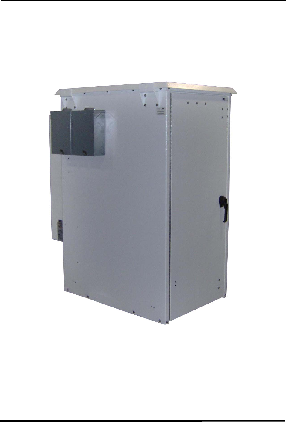
2 Product Description
2.1 Product Overview
The indoor/outdoor 400 Watt DVB-H L-Band transmitter is fully compliant with the DVB-T/H
standard and is designed for an operating range of 1670 MHz to 1675 MHz. The transport
stream input for the unit may either be a DVB-ASI signal or an Gb Ethernet (IP) input (Pro-
MPEG CoP #3 / SMPTE 2022).
Figure 2-1 400 Watt DVB-H Transmitter
The compact design is a complete DVB-H transmitter system. Included in the indoor/outdoor
cabinet is a modulator and high power amplifier (HPA). The transmitter system is also designed
to accommodate a customer installed bandpass filter. In addition to a digital modulator board,
the modulator system also includes an amplifier, bandpass filter, internal GPS receiver, I/O
extension board and a system controller. The system controller is responsible for transmitter
operation, configuration, management and status reporting with support for a SNMP-based
Network Management System.

CL1TC-4 400W DVB-H Transmitter Product Description
Product Manual, Rev. 1 8
The cabinet also includes a 1350 Watt / 1500 VA UPS intended to supply backup power to a
playout server and the modulator. This will ensure site monitoring will continue during a power
outage as well as signal generation to ensure a fast recovery time once power is restored.
Key highlights of the system include
• Compact, self-contained 400 Watt transmitter
• Operating frequency range of 1670 MHz to 1675 MHz
• DVB-T/H Compliant
• Modular construction for easy maintenance
• Modulator with DVB-H modulator/system controller, amplifier, bandpass filter, on-board
GPS receiver and I/O extension board
• High performance LDMOS power amplifier
• RF overdrive, high VSWR and over-temperature protection
• Variable speed (temperature controlled) DC fans
• Linear and Non-linear Digital Pre-correction
• Web interface for remote control and monitoring
• SNMP for network management of the transmitter
• Air conditioned indoor/outdoor cabinet with smoke detector (customer furnished)
• Playout server (customer furnished)
• 1350 Watt / 1500 VA UPS (customer furnished)
CL1TC-4 400W DVB-H Transmitter Product Description
Product Manual, Rev. 1 9
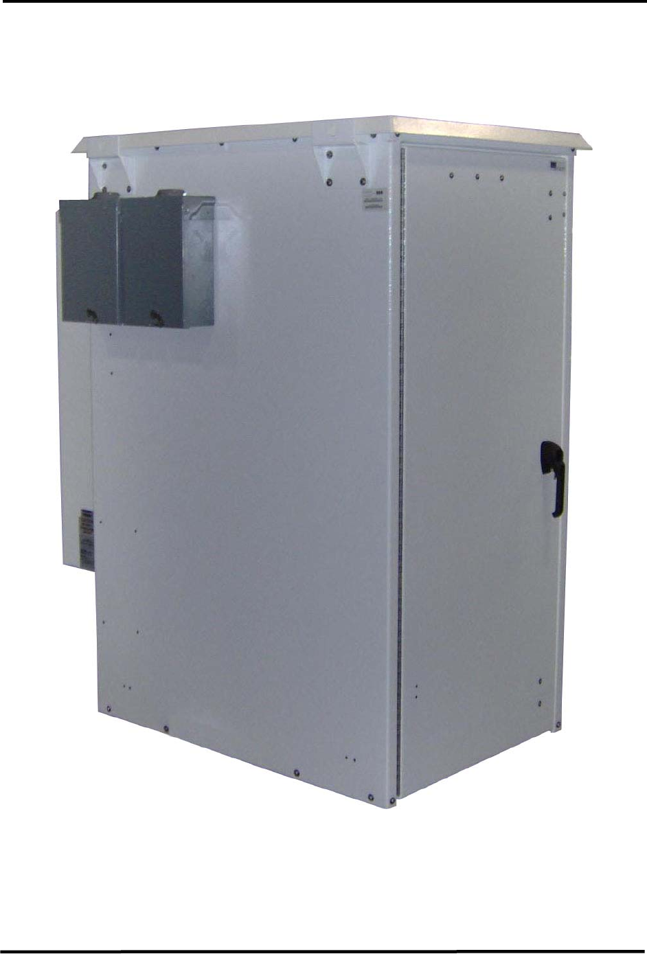
2.2 Cabinet Tour
The front view of the closed cabinet is shown below.
Figure 2-2 Front View of Closed Cabinet
CL1TC-4 400W DVB-H Transmitter Product Description
Product Manual, Rev. 1 10
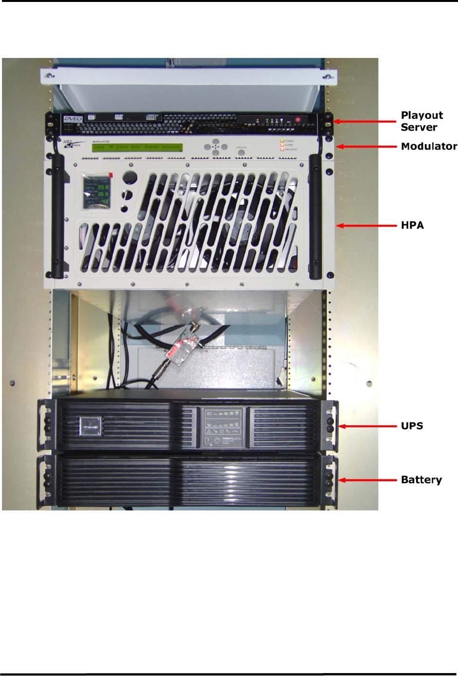
The front view of the open cabinet is shown below.
Figure 2-3 Front View of Open Cabinet
CL1TC-4 400W DVB-H Transmitter Product Description
Product Manual, Rev. 1 11
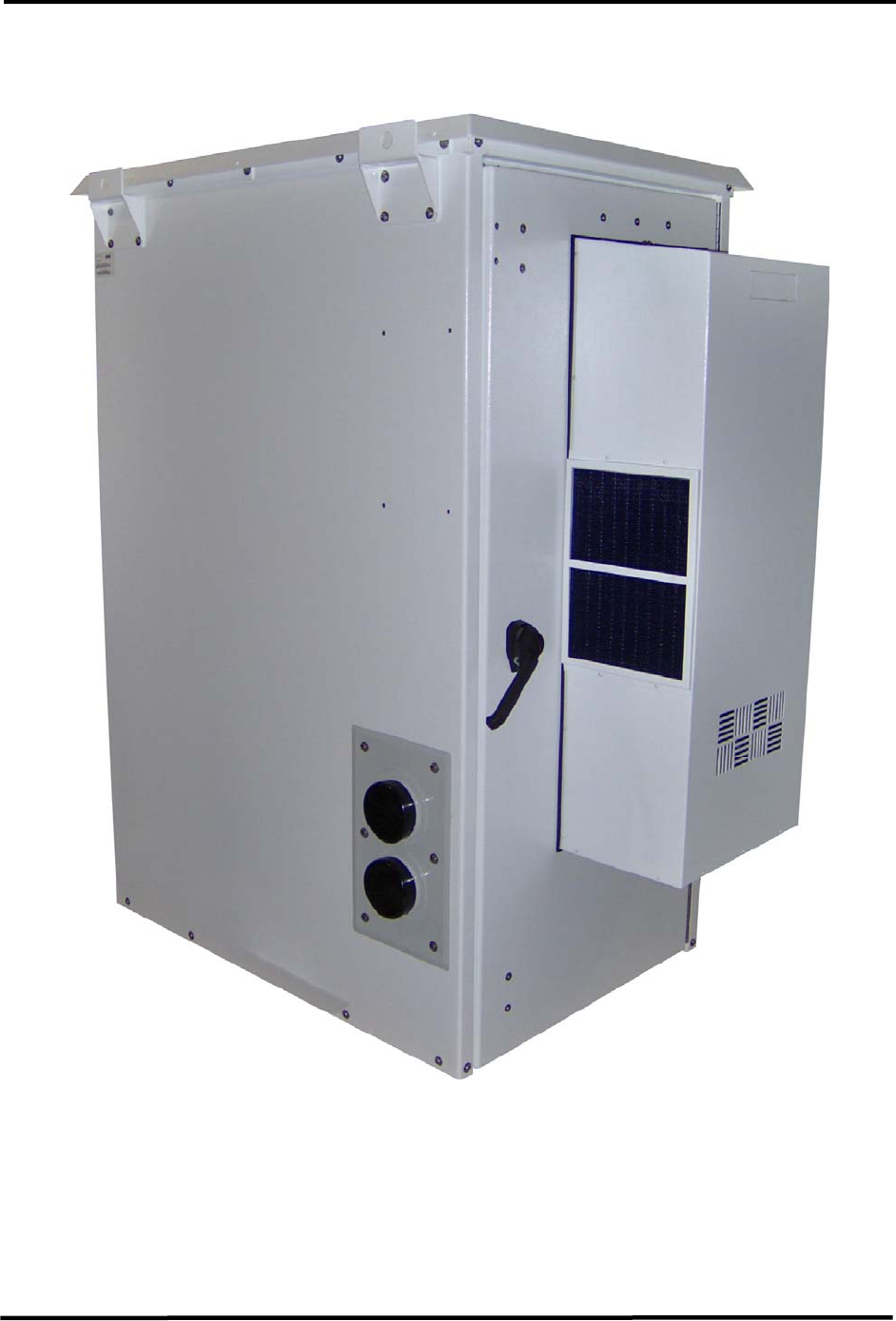
The rear view of the closed cabinet is shown below.
Figure 2-4 Rear View of Closed Cabinet
CL1TC-4 400W DVB-H Transmitter Product Description
Product Manual, Rev. 1 12
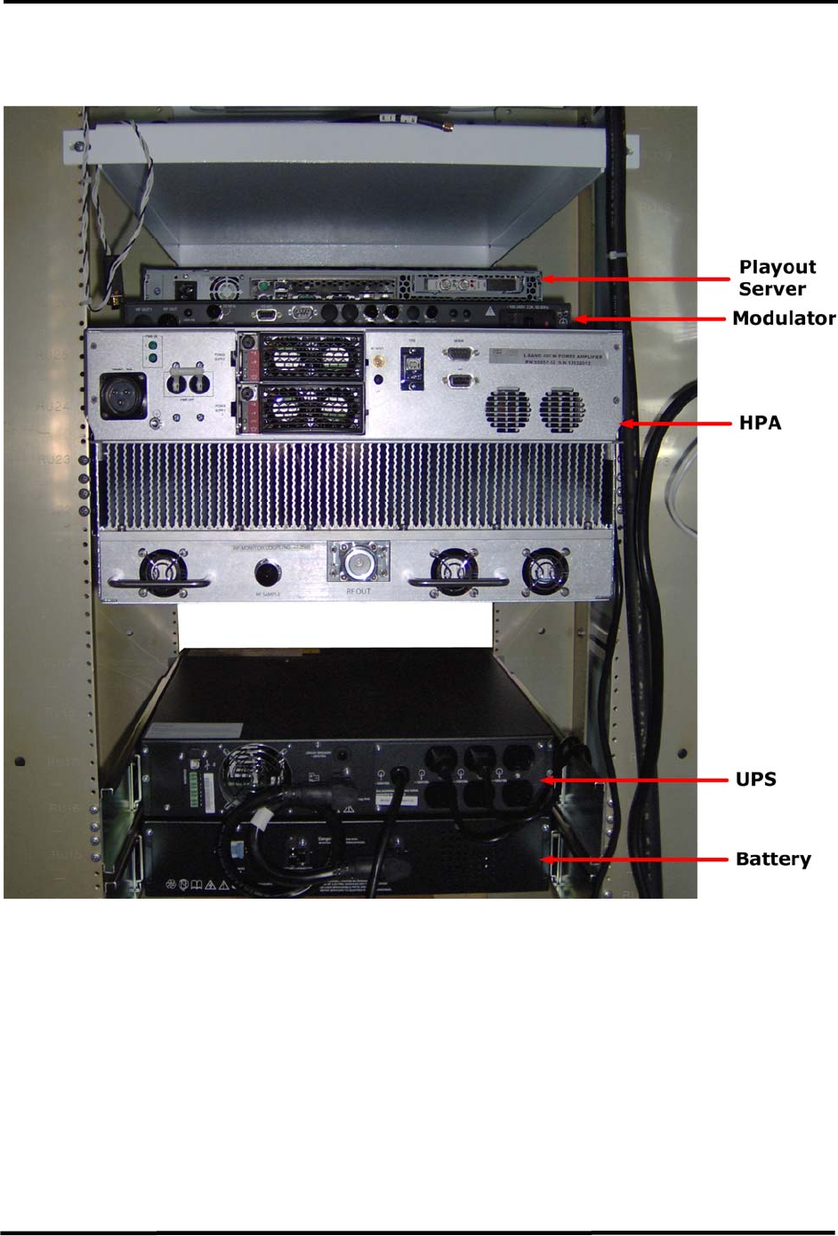
The rear view of the open cabinet is shown below.
Figure 2-5 Rear View of Open Cabinet

CL1TC-4 400W DVB-H Transmitter Product Description
Product Manual, Rev. 1 13
2.3 Product Architecture
2.3.1 Transmitter Overview
The DVB-H transmitter is a compact, indoor/outdoor cabinet that comes equipped with:
• UPS (customer furnished)
• Playout Server (customer furnished)
• Modulator
• HPA
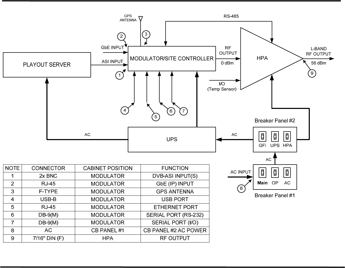
A block diagram of the system is presented in Figure 2-6. Figure 2-6 also identifies the
connector types used for the various modules as well as signal levels and losses throughout the
signal chain.
2.3.2 UPS
A UPS is employed to provide backup power to the playout server and modulator in the event of
a power outage. This ensures that site communications and monitoring will continue during the
outage and to maintain signal generation to ensure a fast recovery time once power is restored.
For details on UPS operation, please refer to the manufacturer’s product manual.
2.3.3 Playout Server
The playout server provides the modulator with a transports stream over ASI.
For details on playout server operation, please refer to the manufacturer’s product manual.
CL1TC-4 400W DVB-H Transmitter Product Description
Product Manual, Rev. 1 14
AC
AC
USB
ETHERNET
RS-232
I/O
(Cabinet Alarms)
Figure 2-6 DVB-H Transmitter Block Diagram

CL1TC-4 400W DVB-H Transmitter Product Description
Product Manual, Rev. 1 15
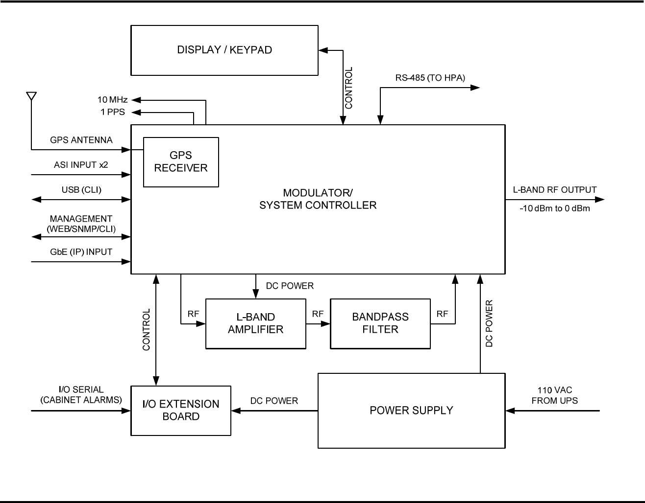
2.3.4 Modulator
The modulator includes
• DVB-H modulator
• Amplifier
• Bandpass filter
• GPS receiver
• I/O extension board
• System controller
Power to the modulator is protected using a UPS power backup (see Figure 2-6). This will
ensure site monitoring will continue during a power outage as well as continued signal
generation to ensure a fast recovery time once power is restored.
2.3.4.1 DVB-H Modulator
• The module performs DVB-H signal encoding, OFDM waveform generation and has
the ability to synchronize with other stations to provide Single Frequency Network
(SFN) operation.
• The module performs the frequency conversion of the OFDM signal into the required
L-Band channel frequency, to drive the high power amplifier (HPA).
• Digital Linear and Non-linear pre-correctors provide compensation for the group
delay introduced by the HPA output filter and the non-linear distortions produced by
HPA.
The DVB-H Modulator receives a MPEG-2 structured Transport Stream on the ASI input or
an IP encapsulated MPEG-2 structured Transport Stream on either of the RJ-45 Ethernet
ports. The IP input is according to MPEG PRO CoP #3 FEC / SMPTE 2022 protocol.
The modulator converts the digital input streams (ASI or IP) to an OFDM waveform in
accordance with DVB-T/H standards. A direct conversion process provides a single analog
RF output from 1670 MHz to 1675 MHz, suitable for amplification in the high power amplifier
(HPA).
Digital linear and non-linear pre-correctors (pre-distorters) significantly improve the
performance of the high power amplifier. The Non-linear pre-corrector compensates for the
HPA non-linearity and is able to provide separate adjustment for the low and high frequency
shoulders of the wide channel spectrum. The Linear pre-corrector compensates for the
group delay created by an output filter.
2.3.4.2 Amplifier
The amplifier provides up to 20 dB of gain, allowing the modulator to provide an RF output
power level from -10 dBm to 0 dBm with shoulders > 55dBc.

CL1TC-4 400W DVB-H Transmitter Product Description
Product Manual, Rev. 1 16
2.3.4.3 Bandpass Filter
Each modulator is equipped with a narrow-band output filter specifically tuned to the frequency
channel assigned to the transmitter. The bandpass filter is intended to limit out-of-band
emissions at the output of the modulator’s internal amplifier.
2.3.4.4 GPS Receiver
The onboard GPS receiver provides accurate, high quality 10 MHz and 1PPS reference
signals for transmitter synchronization and has the capability to track 12 satellites. The 10
MHz and 1PPS reference signals are provided for the modulator board as well as one 10 MHz
and one 1 PPS reference signal for external devices.
The GPS receiver supports the NMEA formatted message protocol as well as the proprietary
NavMan binary messages. A subset of the protocols is used by the processor in order to
control the receiver.
The user has the option to set the Max GPS Holdover time, updated the system clock from
the GPS and set the time zone. Following a loss of signal lock (to the GPS satellite
network), the Max GPS Holdover time is the maximum length of time the system will
continue to operate in a free-running mode before an alarm is issued.
2.3.4.5 I/O Extension Board
The I/O extension board provides four (4) analog pull down inputs and four (4) analog pull
up inputs, which are available on the rear panel I/O port. The analog inputs are monitored
by the system controller permitting the user to set the polarity and voltage threshold that
trigger an alarm.
NOTE: For this application, Pin 6 has been connected to the cabinet door switch contacts,
Pin 7 has been connected to the cabinet smoke detector and the Web interface has been
configured accordingly.
2.3.4.6 Transmitter Controller Module
• Provides all primary site control and management functionality.
• Manages all control interfaces of the transmitter.
The modulator and HPA are connected by a RS-485 serial cable for control and monitoring
(see Figure 2-6). The system controller supports transmitter operation, configuration,
management and status reporting. The control includes power up, power down, RF control
processes, control commands for status requests and operating parameters, etc. The
transmitter identity (name, password, local IP address, SNMP, etc.) can be configured
remotely or locally. Remote upgrade of the transmitter software is supported.
The system controller supports a web interface (Web GUI) for its user interface and is
responsible for software and configuration management. Remote control of the transmitter
is typically managed via an SNMP agent.
CL1TC-4 400W DVB-H Transmitter Product Description
Product Manual, Rev. 1 17
Figure 2-7 Modulator Block Diagram

CL1TC-4 400W DVB-H Transmitter Product Description
Product Manual, Rev. 1 18
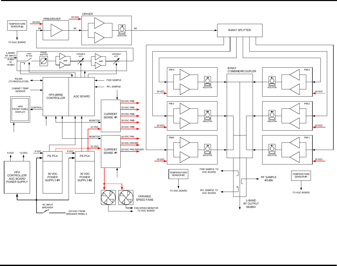
2.3.5 High Power Amplifier (HPA)
• The module provides RF signal amplification up to the required 400 Watts output
power level at the HPA RF output.
• The output power level is maintained via an ALC loop.
• The output forward and reverse power levels are measured by the integrated output
coupler and reported to the system controller.
The main system diagram for the High Power Amplifier (HPA) is shown in Figure 2-8. This
compact design employs a high efficiency LDMOS technology with a 400 Watt power rating. The
HPA includes a LCD display for status messages. The HPA also includes two power supplies and
has two variable speed DC fans for forced air cooling.
The HPA is designed to operate as a final amplification stage for the terrestrial L-Band
transmitter system. It amplifies the L-Band terrestrial signal from the modulator up to a
power level of 400 Watts, while maintaining acceptable output emission levels.
The HPA is a field-replaceable system component that includes integrated AC/DC power
supplies. The HPA is designed for installation in an indoor or environmentally protected
outdoor cabinet.
The HPA architecture is based on a solid state design operating in the Class A/AB linear
mode over a frequency range from 1670 MHz to 1675MHz. The amplifier is fully protected
against input overdrive, overheating and output load VSWR conditions. The protection
circuits are all self-correcting, allowing restoration of the amplifier to the normal operational
state upon removal of the fault condition.
The HPA incorporates an internal automatic self-leveling loop to maintain a constant output
power level. The automatic level control (ALC) circuit will compensate for the input signal
level variations and gain variations affected by changes in temperature as well as for the
gain change due to devices aging.
The HPA main driver chain signal is split and feeds six individual LDMOS power modules. The
output of each module is combined and fed into the combiner/coupler which includes a RF
monitor port and RF detectors to measure forward and reflected power levels. The HPA
controller monitors the operation parameters of the HPA, provides protection against abnormal
operation conditions and communicates with the modulator system controller via a RS-485 serial
link.
There are six output power modules in parallel configuration in the 400W DVB-H HPA. The rated
output power level of the HPA during normal operation is 56 dBm (400W). In the event of a
partial failure (the lowest current reading on one of the power modules is less than 20% of
the highest current reading on one of the power modules), the HPA is capable of operating
with a maximum output power level of 53 dBm. If the output power level is greater than 53
dBm, it will be automatically reduced to 53 dBm. If the output power level is less than 53
dBm, no reduction will occur.
CL1TC-4 400W DVB-H Transmitter Product Description
Product Manual, Rev. 1 19
MONITOR
30 VDC
12 VDC 12 VDC
12 VDC
5 VDC
5 VDC
RF IN
Figure 2-8 400W HPA Block Diagram

CL1TC-4 400W DVB-H Transmitter Product Description
Product Manual, Rev. 1 20
2.3.5.1 HPA Enhanced Features and Design Concepts
The HPA utilizes several innovative features designed to enhance its performance and
reliability of the amplifier.
• Enhanced Heat Sink Design
• Thermally Enhanced Power Transistors
• Variable speed (temperature controlled) DC fans
The HPA employs a heat sink design that permits more equal heat distribution across the
heat sink, thus reducing the maximum operating temperature. Distribution of the main
heat source elements within the HPA is optimized in order to utilize the maximum thermal
efficiency from the heat sink, also resulting in lower operating temperatures.
The HPA design incorporates the latest generation high power LDMOS transistors which
employ a thermally enhanced package. The significant reduction in thermal resistance will
allow these new generation power devices to operate with a lower junction temperature
thus improving overall amplifier reliability.
The variable speed fans allow the fan speed to be increased or decreased as the HPA
temperature increases or decreases. This improves overall efficiency of the HPA and the
lifetime of the fans.
2.3.5.2 HPA Controller
The HPA embedded controller monitors all operating parameters and provides amplifier
protection and control. It communicates with the main system controller via the RS485
interface and reports the following parameters and statuses:
• HPA input power level
• HPA forward power level
• HPA reflected power level
• HPA power supply DC voltage levels
• HPA pre-driver, driver and power module current consumption
• HPA temperature
• HPA fan speed
• HPA RF power inhibit
• HPA input overdrive alarm
• HPA output overdrive alarm
• HPA output reflected power (VSWR) alarm
• HPA failure alarm
• Over-temperature fault
• Pre-drive and driver device (current) fault
• Power module current misbalance fault (results is output power limitation)
• Power module device (current) fault
• Power Supply DC Fault
• Fan stalled alarm

CL1TC-4 400W DVB-H Transmitter Product Description
Product Manual, Rev. 1 21
The following HPA factory control commands are available via USB:
• RF Power enable/disable
• Attenuator control
The HPA is a constant gain block, which is individually calibrated in order to maintain the RF
performance while operating in various conditions. The calibration is performed on the
forward power sensor, reflected power sensor and input power sensor. A calibration table is
stored in the internal EEPROM of the HPA controller.
The HPA controller reports alarms to the system controller and maintains an internal log of
alarms. Each alarm entry in this log contains the alarm ID itself along with monitored
parameters prior to an alarm. This alarm log is saved in an internal EEPROM.
2.4 Breaker Panels
The two (2) breaker panels are mounted on the left wall of the cabinet (when looking at the front
of the cabinet) in the top-left corner of the wall.
Circuit breaker panel 1 receives the input AC power and distributes the required power to circuit
breaker panel 2, as well as the air conditioner.
Circuit breaker panel 2 receives AC power (from circuit breaker panel 1) and distributes the
required power two (2) receptacles as well as the HPA. One of the receptacle provides AC power
to the UPS, internal lights and smoke detector; the other is a GFI.
2.5 Control Interfaces
The modulator serves as the primary system controller responsible for configuration and
management of the entire transmitter and interfaces. The physical interface for system
management is the modulator Ethernet port, which supports Web, SNMP v3 (secure SNMP), and
Telnet.
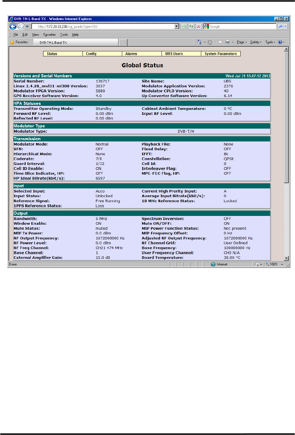
The modulator hosts an internal web interface (Web-GUI) accessible through its Ethernet
management port. The Web-GUI is an intuitive interface allowing the user to access the current
transmitter status and configure the operational parameters of the system. The Web interface
uses a simple hierarchical menu structure which provides access to all transmitter parameters.
Below is a snapshot of the main status screen of the Web-GUI.
The transmitter SNMP interface provides the means for remote management of the transmitter
and to accept alarm traps. The notification options can be configured on a per-alarm basis. The
user may decide to mask certain alarms, increase/decrease integration time to declare an alarm,
etc. Alarm and logs are available via the SNMP interface and are stored in Non Volatile Memory
CL1TC-4 400W DVB-H Transmitter Product Description
Product Manual, Rev. 1 22
Figure 2-9 Web-GUI Main Status Page
2.6 Remote Upgrades
The main software components in the transmitter are remotely upgradeable via the modulator
management interface.

CL1TC-4 400W DVB-H Transmitter Transmitter Technical Specifications
Product Manual, Rev. 1 23
3 Transmitter Technical Specifications
3.1 Modulation Standard
DVB-TH (ETSI EN 300 704 V1.6.1)
Supported Modes IFFT 2k, 4k, 8k
Guard Intervals 1/4, 1/8, 1/16, 1/32
Code Rates 1/2, 2/3, 3/4, 5/6, 7/8
Constellations QPSK, 16-QAM, 64-QAM
Hierarchical Mode None, α = 1, 2, 4
Network Mode SFN and MFN
Bandwidth 5MHz
3.2 Modulator Control Interfaces
Modulator Control Interfaces
Front Panel LCD display and cursor/execute keys
Ethernet Connectors: 2x RJ45
Speed: 10/100/1000 Base-T
USB Connector: USB Type B
RS232 Interface Connector: 9-pin SUB-D (M)
RS485 Interface Connector: 9-pin SUB-D (F)
Must be connected to the HPA Serial interface
I/O Interface Connector: 9-pin SUB-D (M)
Pin 1 to Pin 4 Voltage: 0 to 10 VDC
(analog input – pull down)
Pin 5 to Pin 8 Voltage: 5 VDC (analog input – pull up)
Must be connected to cabinet alarms
Web GUI Internet Explorer 6.0+, Firefox, etc.
Connector: Ethernet
SNMP Control Interface Connector: Ethernet
CLI (Command Line Interface) Connector: USB (HyperTerminal) or
Ethernet (HyperTerminal or Telnet)
Alarm Relays Connector: RS232
Two Dry Contact alarm relays, triggered by any major
alarm.
3.3 Modulator Inputs
Modulator Inputs
DVB-ASI 2 DVB-ASI inputs: BNC (F), 75 Ohm
Ethernet 2 RJ-45 Ports: Port A is active, Port B is disabled
1) GbE Transport Stream - Pro-MPEG CoP #3 / SMPTE
2022
2) Management port Protocol: WEB/Telnet/SNMP
GPS Antenna F-type (F), 75 Ohm

CL1TC-4 400W DVB-H Transmitter Transmitter Technical Specifications
Product Manual, Rev. 1 24
3.4 Modulator Monitoring Outputs
Modulator Monitoring Outputs
DVB-ASI 2 DVB-ASI outputs: BNC (F), 75 Ohm
RF Monitor Connector: SMA (M), 50 Ohm
Level: 30 dB below the RF output level
Clock Reference - 10 MHz Connector: BNC (F)
Frequency: 10 MHz
Level: 10 dBm, ±2.5 dB
Impedance: 50 Ohm or High Impedance (user
selectable)
Time Reference - 1 PPS Connector: BNC (F)
Frequency: 1 PPS
Level: TTL
Trigger: Positive transition
Impedance: 50 Ohm or High Impedance (user
selectable)
3.5 Modulator RF
Modulator RF
Connector N-type (F), 50 Ohm
Frequency 1670 MHz to 1675 MHz
Power Level -10 dBm to 0.0 dBm in 0.1 dB steps
Spectrum Polarity Inverted or non-inverted, selectable
Level Stability ± 0.3 dB
Shoulder Level < -55 dBc
Spurious Level Outside Channel < -60 dBm at 0 dBm output power level
MER ≥ 43 dB
Amplitude Flatness
Center frequency ±2.3 MHz
±0.5 dB
Group delay response:
Center frequency ±2.3 MHz
300 ns, ±100ns
Phase Noise SSB
(measured @ 474 MHz)
100 Hz: < -80 dBc/Hz
1 kHz: < -95 dBc/Hz
10 kHz: < -100 dBc/Hz
100 kHz: < -115 dBc/Hz
1 MHz: < -120 dBc/Hz
Return Loss > 20 dB

CL1TC-4 400W DVB-H Transmitter Transmitter Technical Specifications
Product Manual, Rev. 1 25
3.6 HPA Control Interfaces
HPA Control Interfaces
Front Panel LCD display
USB Interface Connector: USB Type B
HPA Monitor PC GUI
Serial Interface Connector: 9-pin SUB-D (M)
Must be connected to the modulator RS485 interface
I/O Interface Connector: 9-pin SUB-D (F)
Must be connected to the cabinet temperature sensor
3.7 HPA RF Input
HPA RF Input
Connector SMA (F), 50 Ohm
Frequency 1670 to 1675 MHz
Power Level -5.0 dBm to 0.0 dBm
Return Loss < 1.9:1
3.8 HPA/Transmitter RF Output
HPA/Transmitter RF Output
Connector 7/16 DIN (F), 50 Ohm
Frequency 1670 to 1675 MHz
Digital Average Output Power
(before customer installed filter)
400 Watts (56 dBm)
Power Level Accuracy ± 0.5 dB
Gain 61 dB (max.)
Gain Variation over Temperature
≤ ± 1 dB
Gain Variation over 5 MHz
Bandwidth
≤ 0.5 dB
In-band IMD ≤ -27 dBc
Spectral Regrowth
(at rated output power)
≤ -30 dBc
Frequency Stability Internal GPS is used for synchronization
VSWR < 1.2:1
RF Sample Connector: N-type (F), 50 Ohm
Coupling Factor: 45.0 dB, ± 1 dB

CL1TC-4 400W DVB-H Transmitter Transmitter Technical Specifications
Product Manual, Rev. 1 26
3.9 Modulator Digital Pre-Correction
Pre-Correction (non-adaptive)
Linear Pre-Correction
Correction Points 61
Point Spacing 1/60 of nominal spectrum BW
Amplitude Correction ±10 dB
Amplitude Resolution 0.01 dB
Group Delay Correction ±2000 ns
Group Delay Resolution 1 ns
Non-Linear Pre-Correction
Curve Formats S 21 and VO/VI
Amplitude Scale Linear and Logarithmic
Correction Points Max. 256, user-defined position
Gain Correction Max. 12 dB, subject to available headroom
Phase Correction -6 to +30 degrees, subject to available headroom
Peak Power Clip Level +17 dB to +7 dB
(peak power relative to average RMS level)

CL1TC-4 400W DVB-H Transmitter Transmitter Technical Specifications
Product Manual, Rev. 1 27
3.10 GPS
GPS
Recommended Antenna Bullet III GPS antenna -Trimble model no. 57860-10
or equivalent
Receiver Architecture L1 1575.42 MHz
12 Parallel Channels C/A code (1.023 MHz chip rate)
Code plus carrier tracking (carrier aided tracking)
Tracking Capability 12 simultaneous satellite vehicles
Acquisition Time (Time To First
Fix, TTFF)
< 15 seconds typical TTFF-hot (with current almanac,
position, time and ephemeris)
< 150 seconds typical TTFF-cold (no stored
information)
Positioning Accuracy < 5 m, 1 – sigma
< 10 m, 2 - sigma
Timing Accuracy < 2 ns, 1 – sigma
< 6 ns, 6 - sigma
Holdover Time ±1 µsec during 2 hours
10 MHz Output Signal Internally connected to the modulator input
Level: 10 dBm ±2.5 dBm, sine wave Harmonic Level:
-40 dBc max.
Phase Noise 1 Hz: < -75 dBc/Hz
10 Hz: < -110 dBc/Hz
100 Hz: < -125 dBc/Hz
1 kHz: < -135 dBc/Hz
10 kHz: < -155 dBc/Hz
100 kHz: < -155 dBc/Hz
1PPS Output Signal Internally connected to the modulator input
Level: TTL
CL1TC-4 400W DVB-H Transmitter Transmitter Technical Specifications
Product Manual, Rev. 1 28
3.11 Power Supply
3.11.1 Modulator
Modulator Power Supply
Voltage 100 - 240 VAC
Frequency 50-60 Hz
Power Consumption max 50 W max.
3.11.2 HPA
HPA Power Supply
Voltage 195-240 VAC (220 VAC ±10%)
Frequency 50-60 Hz
Power Consumption max 2.5 kW
3.12 Environmental
Environmental
Operating Temperature +41° F to +113° F
(+5° C to +45° C)
Storage Temperature -40° F to +149° F
(-40° C to +65° C)
Relative Humidity max. 95%, non condensing
Cooling Forced air
3.13 Mechanical
3.13.1 Modulator
Modulator Mechanical
Dimensions (W x H x D) 19” x 1.73” x 20.5”
(48.3 cm x 4.4 cm x 52.1 cm)
Weight (unpacked) 15 lbs. (6.8 kg)
3.13.2 HPA
HPA Mechanical
Dimensions (W x H x D) 19” x 8.72” x 30.8”
(48.3 cm x 22.2 cm x 78.2 cm)
Weight (unpacked) 77 lbs. (35 kg)

CL1TC-4 400W DVB-H Transmitter Installation
Product Manual, Rev. 1 29
4 Installation
4.1 Unpacking and Inspection
Each transmitter is completely assembled, tested and shipped in the appropriate packaging.
Carefully unpack the transmitter and examine all shipping containers and contents for physical
damage that might have occurred during shipment. If damage occurred during shipment please
notify your freight carrier immediately.
Missing or damaged equipment not caused by the freight carrier should be directed to UBS-
Axcera Customer Support, in order to facilitate the replacement or repair of the equipment.
Be sure to check the package contents carefully for important documents and materials.
Note
Retain all shipping containers for storage or re-shipment purposes. All
materials returned under warranty must be packed in their original shipping
containers.
4.2 Installation Safety
The installation of the transmitter will require professional and properly trained personnel to
ensure it is installed in observance of the appropriate electrical and safety codes.
4.3 Installation Overview
The transmitter can be installed by following the basic sequence below:
• Transmitter set-up
o Check the installation surface structure, flatness and suitability
o Position the cabinet according to site drawings
• Transmitter AC power
o Connect the transmitter ground
o Connect the Mains AC
• Modulator connections
o Connect the GPS antenna to the modulator GPS input
o Connect the WAN/LAN to the modulator Ethernet port (A or B)
• RF output
o Connect the bandpass filter (customer furnished) to the HPA RF output
o Connect the transmission (or transmission line jumper) to the bandpass filter
output
NOTE: Detailed transmitter installation information can be found in the subsequent sections
of this manual.

CL1TC-4 400W DVB-H Transmitter Installation
Product Manual, Rev. 1 30
4.4 Cabinet Installation
4.4.1 Installation Surface
Before installing the cabinet, check the installation surface structure, flatness and suitability.
4.4.2 Cabinet Positioning
NOTE: Please refer to site drawings for cabinet positioning.
• The cabinet should be positioned within the room to allow for adequate ventilation.
• Sufficient space must be made available in front of the cabinet so that the front door
can be opened and closed, allowing the user to access the playout server, modulator,
HPA and UPS front panels.
• Sufficient space must be made available to the rear of the cabinets so that the rear
door can opened and closed, allowing the user to access the playout server,
modulator, HPA and UPS rear panels, as well as the air conditioner control panel.
• Sufficient space must be made available to the left of the cabinet (when facing the
front of the cabinet) so that the breaker panels can be accessed.
• Sufficient space must be made available to the right of the cabinet (when facing the
front of the cabinet) so that the cable glands can be accessed.
For safety reasons, a minimum of four people is required for any lifting and/or positioning of
the transmitter. The transmitter is mounted on a pallet for easy movement using a pallet
pump truck.
4.5 Mains AC Power
NOTE: Please refer to site drawings for the interconnection of the cabinet to the building
Mains AC distribution panel.
4.5.1 General
A certified Electrician should install the Mains AC power cables to meet all regional and
national electrical codes, and according to the transmitter electrical drawing(s).
NOTE: Please refer to the cabinet vendor’s drawings for Mains AC and Frequency
specifications.
WARNING
VERIFY THAT THE MAINS AC VOLTAGE IS WITHIN
THE SPECIFIED RANGE AND CHECK ALL POWER
CABLES FOR DAMAGE

CL1TC-4 400W DVB-H Transmitter Installation
Product Manual, Rev. 1 31
4.5.2 Electrical Safety
• All transmitter equipment, electrical power switches and circuit breakers must be
turned off during installation.
• Ensure that the Mains AC power cable connecting the main circuit breaker to the
service panel is the last cable connected during installation.
• Ensure that the transmitter main circuit breaker and all PDU circuit breakers are
turned off prior to working on internal transmitter parts or connecting cables.
4.5.3 Cabinet Wiring
All cabinet components are pre-wired to the cabinet breaker panels and cabinet receptacles.
In this case, only the cabinet main circuit breaker needs to be connected to an external AC
power source.
4.5.3.1 Cabinet Grounding
NOTE: Please refer to the cabinet vendor’s drawings for the grounding location on the
cabinet.
4.5.3.2 Mains AC Power Cable
NOTE: Please refer to the cabinet vendor’s drawings for the Main AC connection point on
the cabinet.
WARNING
THE CABINET MUST BE CONNECTED TO THE
BUILDING/SITE MAIN GROUND TERMINAL
DANGER
BEFORE YOU CONNECT THE MAINS AC POWER CABLE
TO THE CABINET, DISCONNECT IT FROM THE
BUILDING DISTRIBUTION PANEL
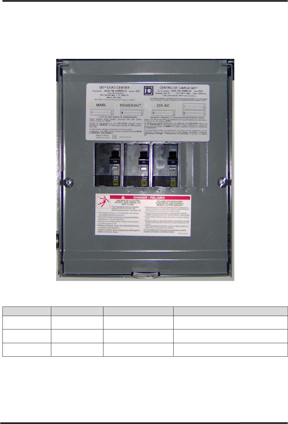
CL1TC-4 400W DVB-H Transmitter Installation
Product Manual, Rev. 1 32
4.6 Breaker Panels
4.6.1 Breaker Panel 1
Breaker panel 1 houses three circuit breakers.
Figure 4-1 Breaker Panel 1 (with front cover raised)
Breaker # Name Description Breaker Use
1/2 MAIN 100A, 220 VAC Mains AC input
3/4 POWEROUT 60A, 220 VAC AC output to breaker panel 2
5/6 220 AC 20A, 220 VAC Air conditioner
Table 4-1 Breaker Panel 1 Circuit Breakers
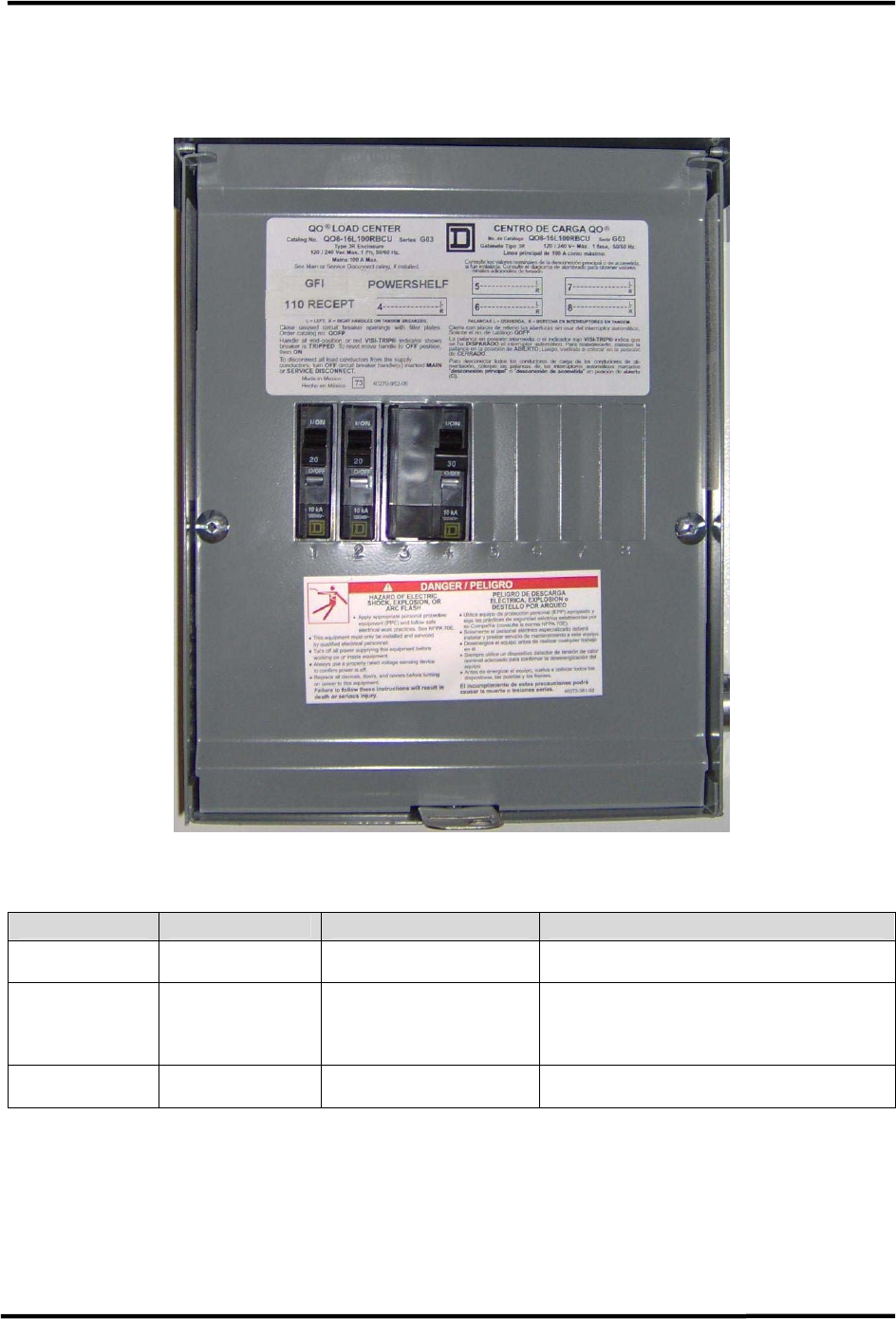
CL1TC-4 400W DVB-H Transmitter Installation
Product Manual, Rev. 1 33
4.6.2 Breaker Panel 2
Breaker panel 2 houses three circuit breakers.
Figure 4-2 Breaker Panel 2 (with front cover raised)
Breaker # Name Description Breaker Use
1 GFI 20A, 110 VAC GFI receptacle
2 110 RECEPT 20A, 110 VAC
Receptacle which feeds UPS,
cabinet lights and cabinet smoke
alarm
3/4 POWERSHELF 30A, 220 VAC HPA
Table 4-2 Breaker Panel 1 Circuit Breakers
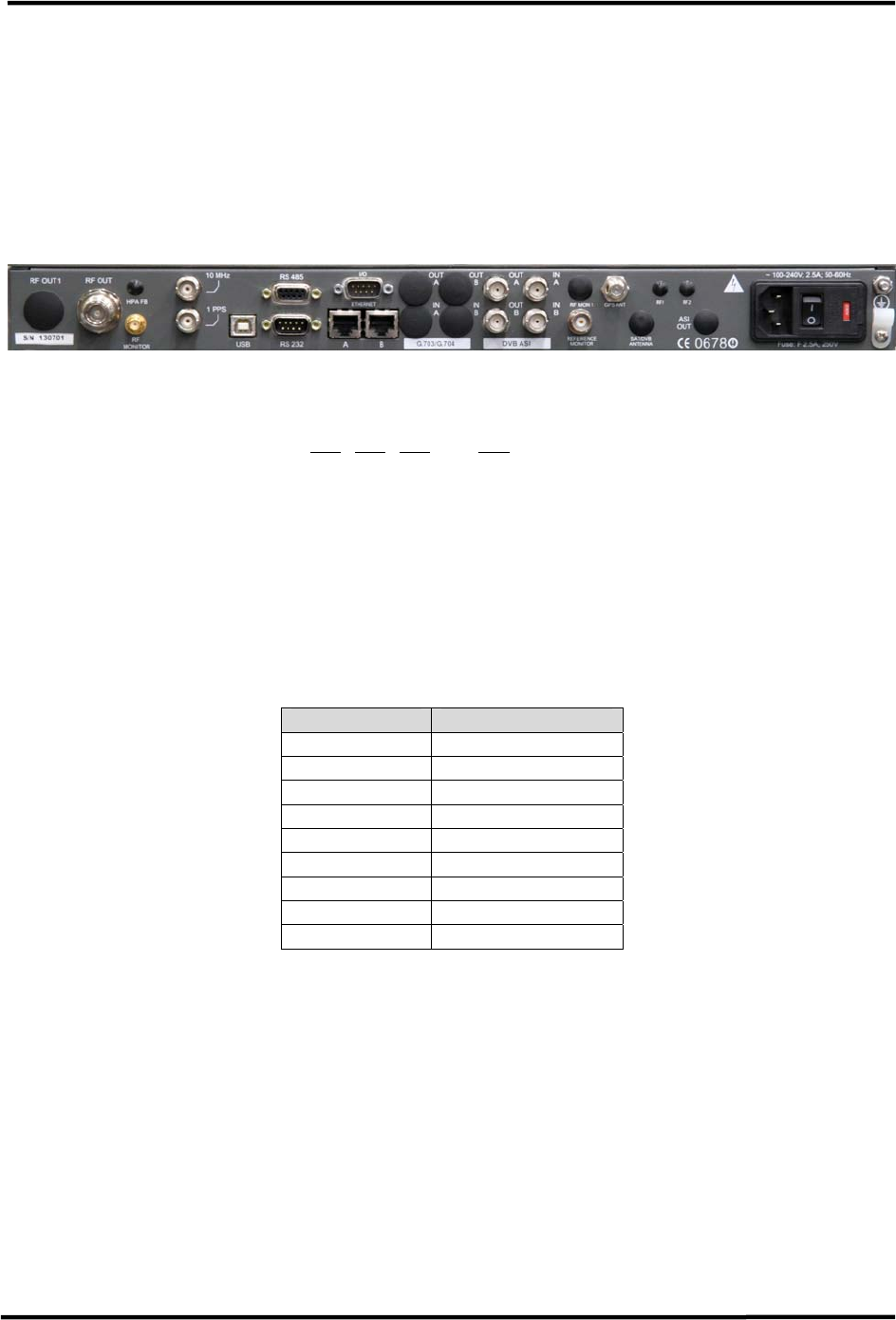
CL1TC-4 400W DVB-H Transmitter Installation
Product Manual, Rev. 1 34
4.7 Cabinet Sub-Assemblies
4.7.1 Modulator Installation
The user is required to connect the following cables to the modulator rear panel:
• GPS antenna RF cable to the GPS input
• WAN/LAN Ethernet cable to Ethernet port A or B
Figure 4-3 Modulator Rear Panel
NOTE: Please refer to sections 3.2, 3.3, 3.4 and 3.5 for a detailed description of the
modulator rear panel interfaces.
4.7.1.1 RS232 Serial Port
The RS232 serial port is configured to provide two Alarm Relays.
The alarm relay contacts are normally open and close on alarm; when the modulator is
turned off the contacts are normally closed. Each relay is software controlled and can be
set to trigger on a specific alarm.
Pin No Function
1 Relay 1 contact
2 RxD
3 TxD
4 Relay 2 contact
5 GND
6 Relay 1 contact
7 RTS
8 CTS
9 Relay 2 contact
Table 4-3 RS232 Serial Port Pin-out

CL1TC-4 400W DVB-H Transmitter Installation
Product Manual, Rev. 1 35
4.7.1.2 I/O Serial Port
Four (4) analog pull down inputs and four (4) analog pull up inputs are available on the I/O
serial port. The analog inputs are monitored by the system controller permitting the user to
set the polarity and voltage threshold that trigger an alarm. See Section 6.5.2 for external
voltage threshold settings and Section 6.5.1 for alarm and trap notification settings.
Pin 1 though pin 4 can be set to report an alarm when the input voltage is greater than (>)
or less than (<) a user defined value. Typically, these pins would be used to monitor an
active device, such as a UPS, that would provide logical voltage levels used to indicate
alarm / no alarm conditions.
Pin 5 through pin 8 can be set to report an alarm when the voltage is greater than (>) or
less than (<) a user defined value. These pins are factory configured to provide 5 VDC and
are typically used to monitor a passive device, such as a magnetic door sensor.
NOTE: For this application, Pin 6 has been connected to the cabinet door switch contacts,
Pin 7 has been connected to the cabinet smoke detector and the Web interface has been
configured accordingly.
Pin No Function Pin Voltage
1 Analog Input (pull down) 0 to 10 VDC
2 Analog Input (pull down) 0 to 10 VDC
3 Analog Input (pull down) 0 to 10 VDC
4 Analog Input (pull down) 0 to 10 VDC
5 Analog Input (pull up) 5 VDC
6 Analog Input (pull up) 5 VDC
7 Analog Input (pull up) 5 VDC
8 Analog Input (pull up) 5 VDC
9 Ground -
Table 4-4 I/O Serial Port Pin-out
4.7.1.3 RS485 Serial Port
The RS485 serial port is used for communication (Machine to Machine) with the HPA.
Pin No Function
1 Relay 1 contact
2 Ground
3 External Reset
4 Rx-
5 Tx+
6 Relay 1 contact
7 Ground
8 Rx+
9 Tx-
Table 4-5 RS485 Serial Port Pin-out
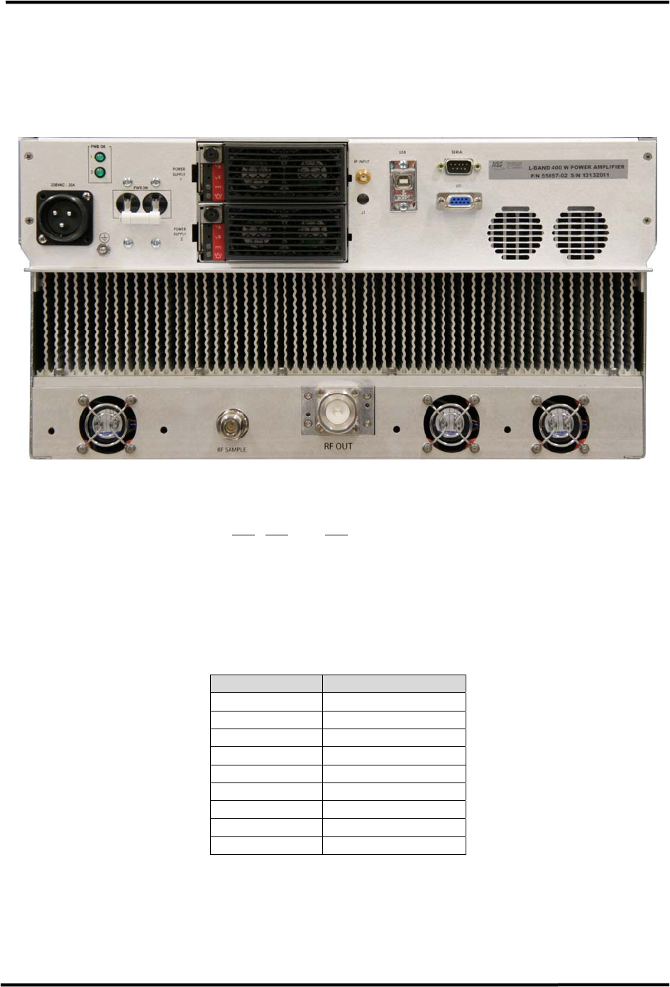
CL1TC-4 400W DVB-H Transmitter Installation
Product Manual, Rev. 1 36
4.7.2 HPA Installation
The user is required to connect the following cable to the HPA rear panel:
• RF cable between the HPA RF Output and the bandpass filter input
Figure 4-4 HPA Rear Panel
NOTE: Please refer to sections 3.6, 3.7 and 3.8 for a detailed description of the HPA rear
panel interfaces.
4.7.2.1 Serial Port
The Serial (RS485) port is used for communication (Machine to Machine) with the
modulator.
Pin No Function
1 N/C
2 N/C
3 N/C
4 Tx-
5 Rx+
6 N/C
7 N/C
8 Tx+
9 Rx-
Table 4-6 RS485 Serial Port Pin-out

CL1TC-4 400W DVB-H Transmitter Commissioning and Operation
Product Manual, Rev. 1 37
5 Commissioning and Operation
5.1 Introduction
This section outlines the installation inspection, initial on-site turn on procedure and
addresses the process for monitoring and control of the CL1TC-4 Transmitter. It also
provides a description of control interfaces and indicators for the transmitter.
5.2 Installation Verification
Before the transmitter can be turned on, the installation must be completed. Please check
the following to ensure all interconnections have been made correctly:
• Verify that no equipment was damaged during the installation.
• Verify that the ground conductor and Mains AC power cables have been connected to
the transmitter cabinet.
• Verify that all cabinet sub-assemblies have been installed correctly and that the
following connections have been made:
o Factory installed cables are connected to the modulator.
o Factory installed cables are connected to the high power amplifier.
o GPS antenna is connected to the modulator GPS input.
o Transport stream is connected to the modulator ASI or GbE inputs.
o Ethernet (WAN or LAN) cable is connected to the modulator Ethernet connector.
• Verify that the high power amplifier RF output is connected to the customer installed
band pass filter and that all connections are tight.
• Verify that the RF transmission line and broadcast antenna have been swept.
• Verify that the band pass filter is connected to the broadcast antenna (or terminated
into a high power load) and that all connections are tight.
5.3 Initial On-Site Turn-on Procedure
Once the CL1TC-4 transmitter is installed and all input, output and AC connections are
made, the system is ready for the initial on-site turn on. Ensure that the output of the
transmitter is connected to a transmission line feeding a broadcast antenna before
proceeding with the turn on.
5.3.1 Transmitter AC Power-up Procedure
1. Switch on the Mains AC circuit breaker located in the building service panel.
2. Switch on the Mains AC circuit breaker located in cabinet breaker panel 1.
3. Switch on the air conditioner circuit breaker located in cabinet breaker panel 1.
4. Switch on the cabinet breaker panel 2 circuit breaker located in cabinet breaker
panel 1.
5. Switch on the 110 VAC receptacle circuit breaker located in cabinet breaker panel 2.

CL1TC-4 400W DVB-H Transmitter Commissioning and Operation
Product Manual, Rev. 1 38
6. Turn on the UPS by pressing the power button on the UPS front panel.
7. Turn on the playout server by pressing the power button on the playout server front
panel.
8. Turn on the modulator AC power switch located on the modulator rear panel. All
three front panel LED’s will flash while the modulator goes through its boot-up
process.
9. Turn on the HPA circuit breaker located in cabinet breaker panel 2.
10. Turn on the HPA AC power switch located on the HPA rear panel. The front panel
LCD and rear panel PWR OK LED’s will turn on.
5.3.2 Configuring the Transmitter
The transmitter has been factory configured with the customer specified television standard,
channel bandwidth and centre frequency.
The user will be required to:
• Configure the modulator network parameters for remote network access.
• Configure the modulator transport stream input parameters.
• Configure the transmission (modulation) parameters and network mode (MFN or SFN)
5.3.2.1 Configuring the Network Parameters
The modulator must be configured correctly, before it can be placed on a network and
operated remotely through either of the rear panel Ethernet connectors.
To configure modulator for remote operation, the user must:
1. Connect a PC to either of the modulator rear panel Ethernet connectors.
2. Open a Web browser.
3. Enter the default IP address of the modulator in the Web browser address bar.
4. When the login page appears, enter “admin” in the password field. Note: The
username field must be left blank.
5. Once logged in, navigate to System Parameters -> Network Parameters and re-
configure the modulator’s network parameters as desired – see Figure 5-1. Note:
The Management port refers to Ethernet connector A, while the Second Etherport
refers to Ethernet connector B.
6. Once the Network Parameters have been re-configured, navigate to System
Parameters -> System Reset and reset the modulator – see Figure 5-2. Note: The
modulator must be reset for Network Parameter changes to take effect.
7. Once the modulator completes it reboot process, connect your network device to the
modulator’s rear panel Ethernet connector.
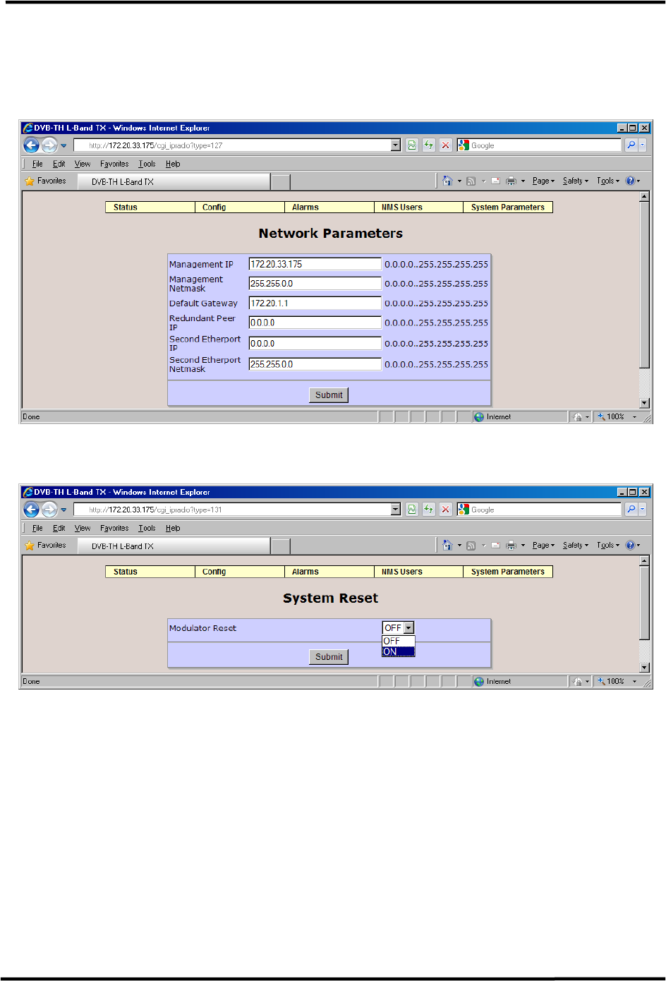
CL1TC-4 400W DVB-H Transmitter Commissioning and Operation
Product Manual, Rev. 1 39
Note: The default IP address for the modulator is 172.20.33.69
Note: The default password for the Web GUI is “admin”
Figure 5-1 Network Parameters
Figure 5-2 System Reset
Alternatively, the modulator front panel LCD and cursor/EXECUTE keys can be used to
configure the modulator’s network parameters.
1. Navigate to the Status Display window “f” and press the “Execute” button. This will
take the user to a System Parameters sub-menu where the network parameters can
be re-configured as desired.
2. Once the Network Parameters have been re-configured, navigate to System
Parameters -> System Reset and reset the modulator.
3. Once the modulator completes it reboot process, connect your network device to the
modulator’s rear panel Ethernet connector.
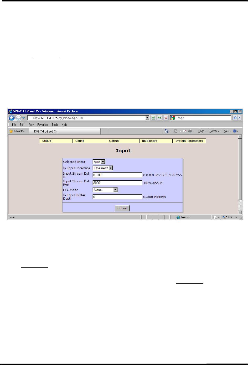
CL1TC-4 400W DVB-H Transmitter Commissioning and Operation
Product Manual, Rev. 1 40
5.3.2.2 Configuring the Input Parameters
The modulator must be configured correctly, before it can lock to the input transport
stream.
1. Navigate to Config -> Input to configure the DVB-ASI or GbE (IP) input settings –
see Figure 5-3.
2. When a transport stream is connected to ASI input, Selected Input can be configured
for automatic selection, or the user can select the DVB-ASI input connector
manually. No other input parameters need to be configured.
3. When a GbE transport stream is connected to either of the Ethernet connectors, IP
Input Interface, Input Stream Dst IP and Input Stream Dst Port must be configured
correctly.
Figure 5-3 Input Configuration
5.3.2.3 Configuring the Modulation Parameters
1. Navigate to Config -> Modulator Mode to ensure Normal operation is selected – see
Figure 5-4. Normal mode must be selected for OFDM carrier generation.
2. Navigate to Config -> Transmission to configure the network mode (MFN or SFN)
and/or configure the DVB-H modulation parameters – see Figure 5-5.
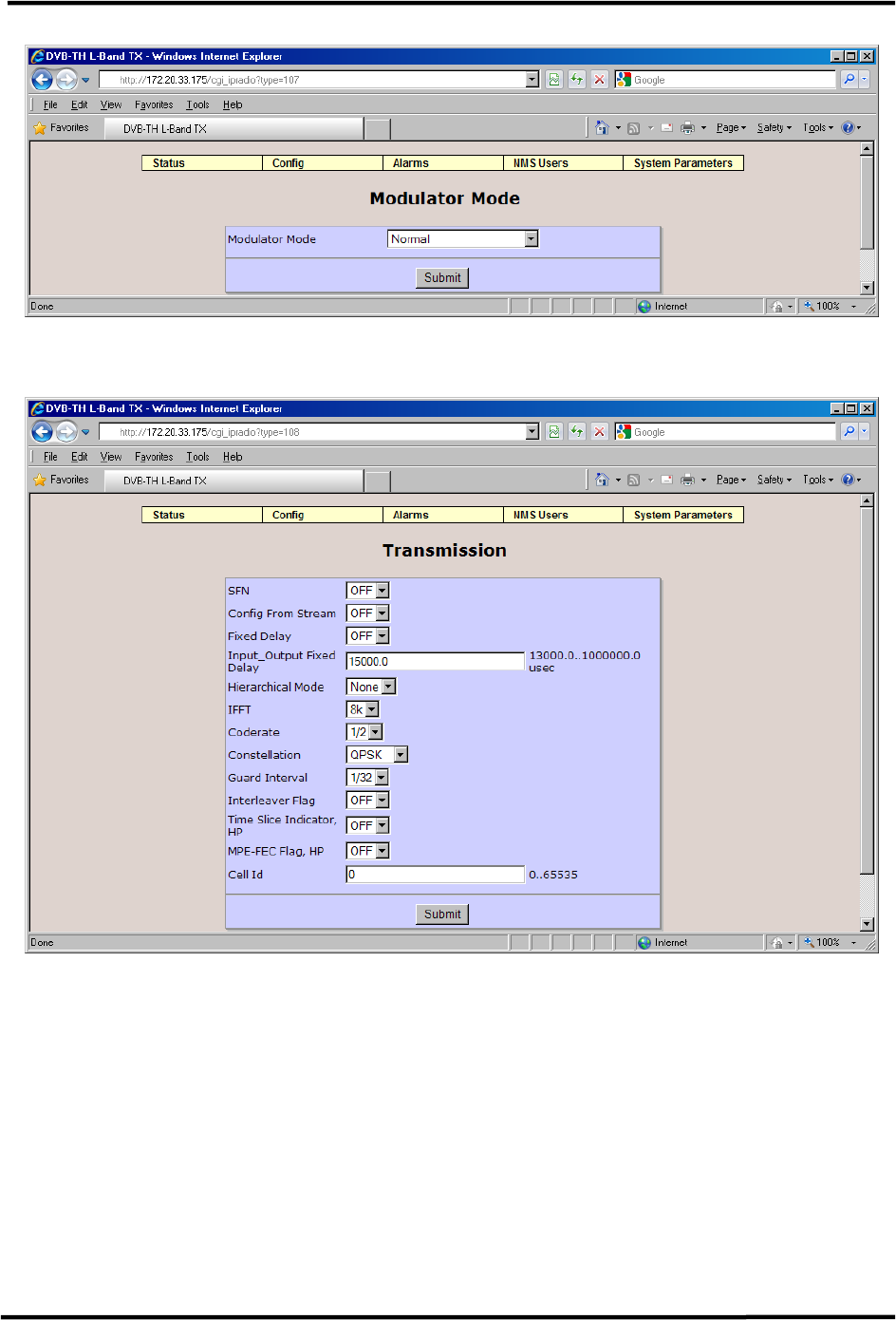
CL1TC-4 400W DVB-H Transmitter Commissioning and Operation
Product Manual, Rev. 1 41
Figure 5-4 Modulator Mode
Figure 5-5 Transmission (Modulation) Parameters
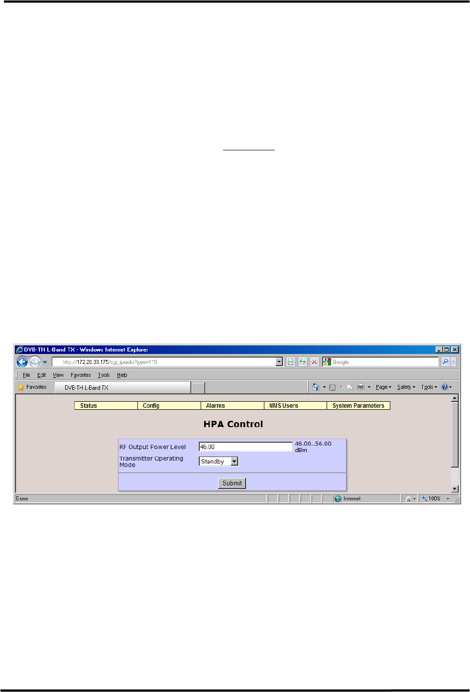
CL1TC-4 400W DVB-H Transmitter Commissioning and Operation
Product Manual, Rev. 1 42
5.3.3 Turning On the RF Output
1. Check the Alarm Status screen for active alarms. The only alarm present should be
GPS Quality Low. The GPS Quality Low alarm will take up to 5 minutes to clear as
satellites are acquired.
2. During the initial on-site turn on, it is recommended to set the transmitter output
level to 46 dBm (minimum value) before the transmitter is placed in Broadcast
mode. This will ensure that the effects of a transmission line or antenna fault are
minimized when the RF is turned on. Navigate to Config –> HPA Control and set the
output power level to 46 dBm – see Figure 5-6.
3. For SFN operation, check the Alarm Status screen to ensure that the GPS Quality
Low alarm has cleared. Once the alarm has cleared, the transmitter can be placed in
Broadcast mode. Note: For MFN operation, the GPS is not required to be locked.
4. From the HPA Control page, set the Transmitter Operating Mode to Broadcast.
5. The modulator front panel Status Display window “i”, HPA front panel LCD, or Web
GUI Global Status page can be used to monitor the transmitter forward and reflected
power levels. Alternatively, a power meter can be connected to the HPA sample port
to monitor the forward power level.
6. If the forward and reflected power levels are acceptable, increase the RF Output
Power Level by 3 db and continue to monitor the forward and reflected power levels.
7. Continue to increase the RF Output Power Level by 3 dB, until the desired output
level is reached (max of 56 dBm).
Figure 5-6 HPA Control
5.3.4 Turning Off the RF Output
Before turning off the AC power switch, the user should set the Transmitter Operating Mode
to Standby. This will ensure that the next time the transmitter is powered on, it will be
powered on in Standby mode.

CL1TC-4 400W DVB-H Transmitter Commissioning and Operation
Product Manual, Rev. 1 43
5.4 Control and Communication
The Transmitter can be controlled and monitored locally (on-site), or remotely from a
Network Management System (NMS).
5.4.1 Control and Communication Interfaces
There are two interfaces port provided for control and communication:
• Ethernet Port A or B (RJ-45) – used for local control with a laptop PC and remote
access through a LAN. Web GUI, SNMP and CLI (Telnet and HyperTerminal)
protocols are supported.
• USB Port (Type B) – used for local control, initial setup, status information and
troubleshooting with a laptop PC. A Command Line Interface (CLI) telnet session is
the supported protocol.
For a detailed description of the Web-GUI interface refer to Section 6.
For a detailed description of the CLI interface refer to Section 7.
5.4.2 Local Access
The transmitter can be controlled and monitored locally (on site) through Ethernet Port A or
B and/or the USB port with a PC. The modulator front panel LCD and cursor/execute keys
can also be used for local access.
The Ethernet ports provide access to the Web GUI and CLI (through Telnet). The USB
interface provides access to the CLI, which allows the operator to perform initial
setup/troubleshooting when network connectivity is not available or desired.
5.4.3 Remote Access
The Network Management System (NMS) operator can control and monitor the transmitter
remotely through Ethernet Port A or B and LAN using the Web GUI and/or SNMP interfaces.
5.5 Modes of Operation
There are two main parameter groups which determine the operating mode, the Transmitter
Operating Mode parameter group and the Modulator Operating Mode parameter group.
5.5.1 Transmitter Operating Modes
The chief transmitter operating modes are Broadcast and Standby.
If the transmitter experiences an AC power interruption under normal, no fault conditions,
the transmitter’s AC power-up algorithm will restore the mode of operation that was active
prior to the AC power interruption, once power is restored.

CL1TC-4 400W DVB-H Transmitter Commissioning and Operation
Product Manual, Rev. 1 44
5.5.1.1 Broadcast Mode
The transmitter normally operates in broadcast mode, allowing it to transmit a broadcast
signal and run all protection loops and ALC. It receives a transport stream signal, or
generates an internal test signal and transmits an OFDM signal for terrestrial broadcast. In
this mode, all transmitter functions are automatically maintained by the modulator
controller.
To operate in broadcast mode, the following conditions must be met:
• The transmitter must be receiving an input signal and be locked to the input stream
(if the modulator is in test mode, the input signal presence is ignored).
• The ALC loop must be running.
• For Single Frequency Network (SFN) operation, the system must have a GPS signal
lock with no alarms (if the modulator is in test mode, the GPS signal presence is
ignored).
• There must be no modulator alarms.
• There must be no HPA alarms.
5.5.1.2 Standby Mode
In this mode the transmitter output is muted by turning the HPA RF switch off and muting
the modulator output.
The operating conditions in Standby Mode are:
• AC power is supplied to the modulator and HPA
• The HPA RF switch is off
• The modulator output is muted
5.5.2 Modulator Operating Modes
The five modulator modes are: Normal, CW, Test 1 (Carriers Removed), Record and
Playback.
In Normal mode, the modulator generates a complete DVB-H waveform. CW and Test 1 are
special test modes not used in regular operation. The CW mode generates a narrow-band
frequency tone and the Test 1 mode suppresses a set of OFDM carriers in the center of the
band (useful for checking for interference, factory configurable). Record and Playback are
described in Section 6.4.1.
5.6 Indicators and Controls
The transmitter main subassemblies have individual indicators and controls used in normal
operation. This includes:
• DVB-H Modulator
• HPA
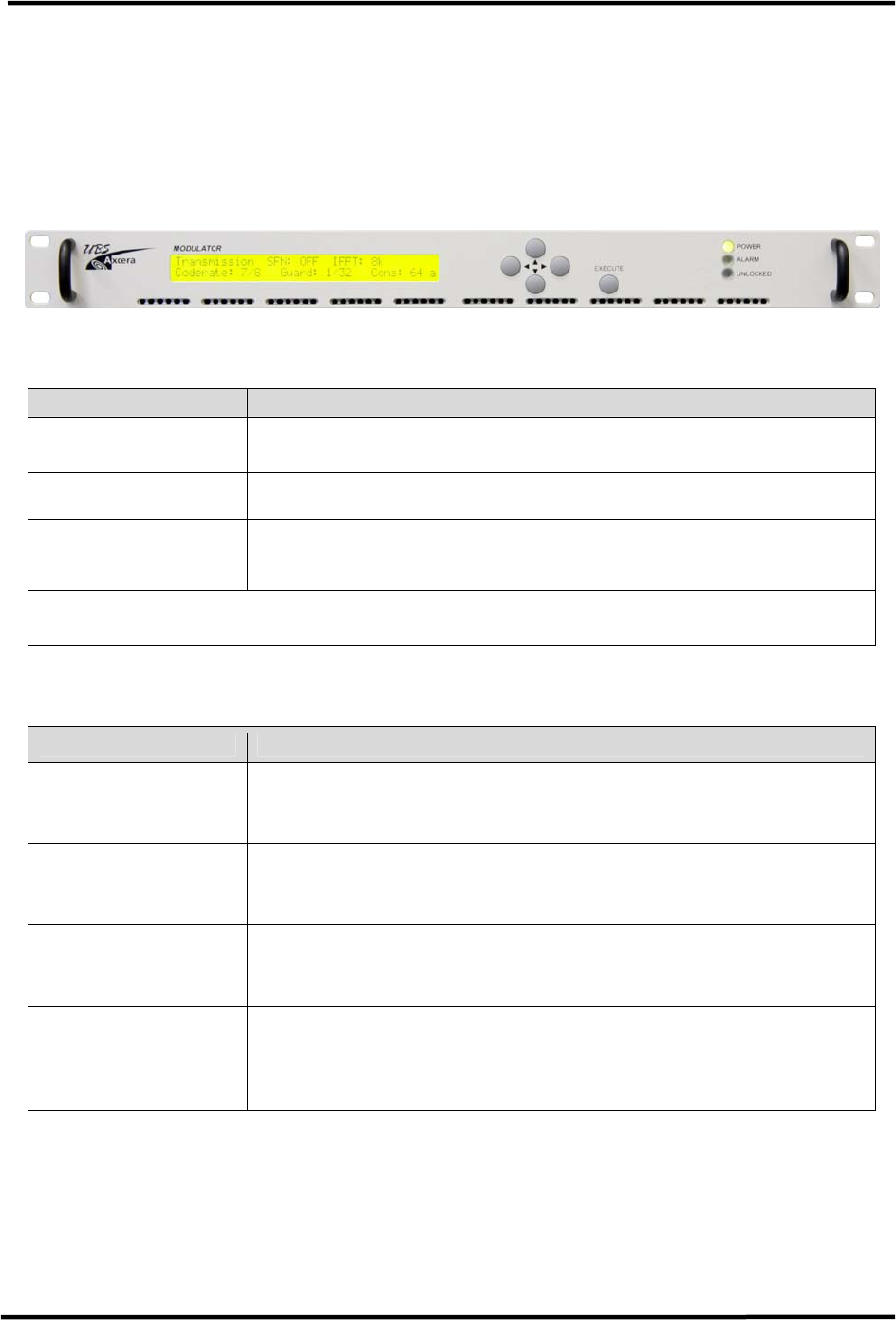
CL1TC-4 400W DVB-H Transmitter Commissioning and Operation
Product Manual, Rev. 1 45
5.6.1 Modulator
5.6.1.1 Front Panel
The two line by forty characters LCD display, in conjunction with four cursor keys and an
EXECUTE button allow easy operation of the modulator. Three LED are provided as status
indicators. For a detailed description of front panel operation, please refer to Section 8.
Figure 5-7 Modulator Front Panel
LED Description
POWER (Green) This Green LED indicates that the modulator AC power supply
has been turned on.
ALARM (Red) This Red LED indicates that there is an active transmitter
alarm.
UNLOCKED (Red) This Red LED indicates that the modulator has failed to
synchronize to the incoming transport stream or if the
incoming transport stream is absent.
NOTE: All LEDs flash green during the boot-up process.
Table 5-1 Modulator Front Panel Status LEDs
Pushbutton Function
EXECUTE Used to enter the configuration menu system (GENERIC or
SPECIFIC) from a status display window, to enter a sub-menu
and confirm changes made to configurable parameters.
c (up)
Used to scroll through the different status display windows,
exit the current menu and enter a higher-level menu, increase
alpha-numerical parameters or abort confirmation of a change.
d (down) Used to scroll through the different status display windows,
exit the current menu and enter a sub-menu, decrease alpha-
numerical parameters or abort confirmation of a change.
e (left)
f (right)
Used to scroll horizontally through the Config menus, the
parameter listings and the parameter characters, in the case of
editable parameters. They are also used to increase and
decrease % parameters.
Table 5-2 Modulator Front Panel Pushbutton Functions
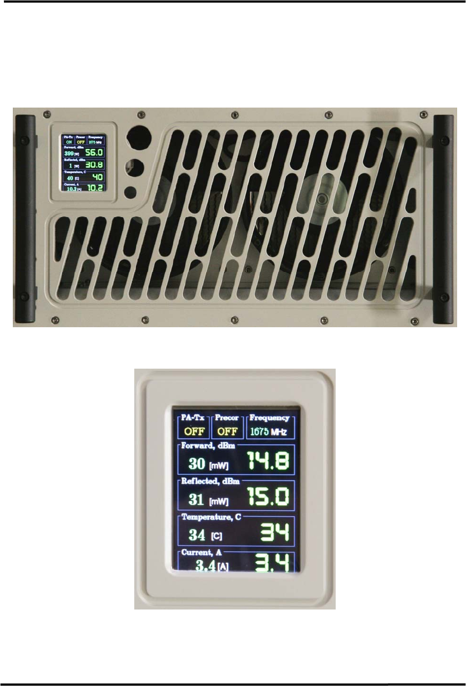
CL1TC-4 400W DVB-H Transmitter Commissioning and Operation
Product Manual, Rev. 1 46
5.6.2 HPA
5.6.2.1 Front Panel
The HPA front panel LCD indicates the status of the HPA Forward Power, Reflected Power,
Temperature and Current as well as several other parameters.
Figure 5-8 HPA Front Panel
Figure 5-9 HPA Front Panel LCD (Standby Mode)
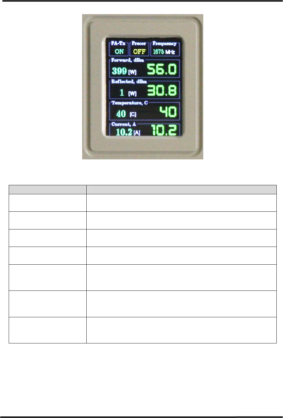
CL1TC-4 400W DVB-H Transmitter Commissioning and Operation
Product Manual, Rev. 1 47
Figure 5-10 HPA Front Panel LCD (Broadcast Mode)
Parameter Description
Forward, dBm (W)
Displays the HPA forward (output) power measured by the
internal HPA combiner/coupler RF detector.
Reflected, dBm (W)
Displays the HPA reflected power measured by the internal
HPA combiner/coupler RF detector.
Temperature, C
Displays the highest temperature measured by one of the
HPA temperature sensors.
Current, A Displays the highest current measured on one of the power
modules.
PA-Tx Indicates the HPA transmission status (ON or OFF)
Precor Not used for this application (always OFF).
Frequency Indicates the transmitter frequency, which is set by the
modulator.
Table 5-3 HPA Front Panel LCD Status
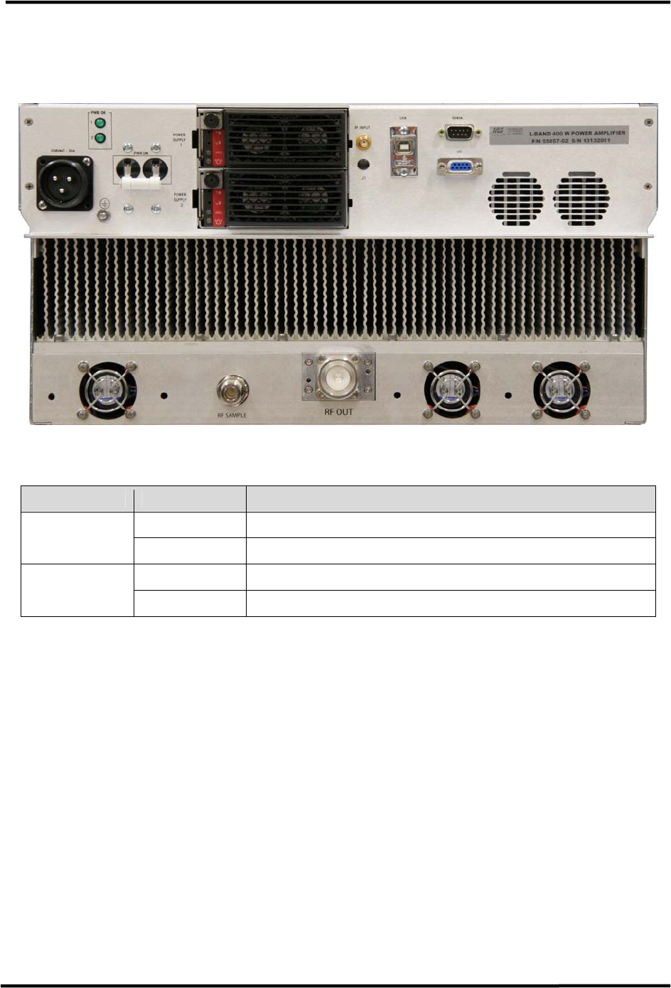
CL1TC-4 400W DVB-H Transmitter Commissioning and Operation
Product Manual, Rev. 1 48
5.6.2.2 Rear Panel
The HPA rear panel includes two AC status LED’s.
Figure 5-11 HPA Rear Panel
LED Color Description
OFF Power supply 1 AC input is not present. PWR OK 1
Green Power supply 1 AC/DC input is present.
OFF Power supply 2 AC input is not present. PWR OK 2
Green Power supply 2 AC/DC input is present.
Table 5-4 HPA Rear Panel LEDs
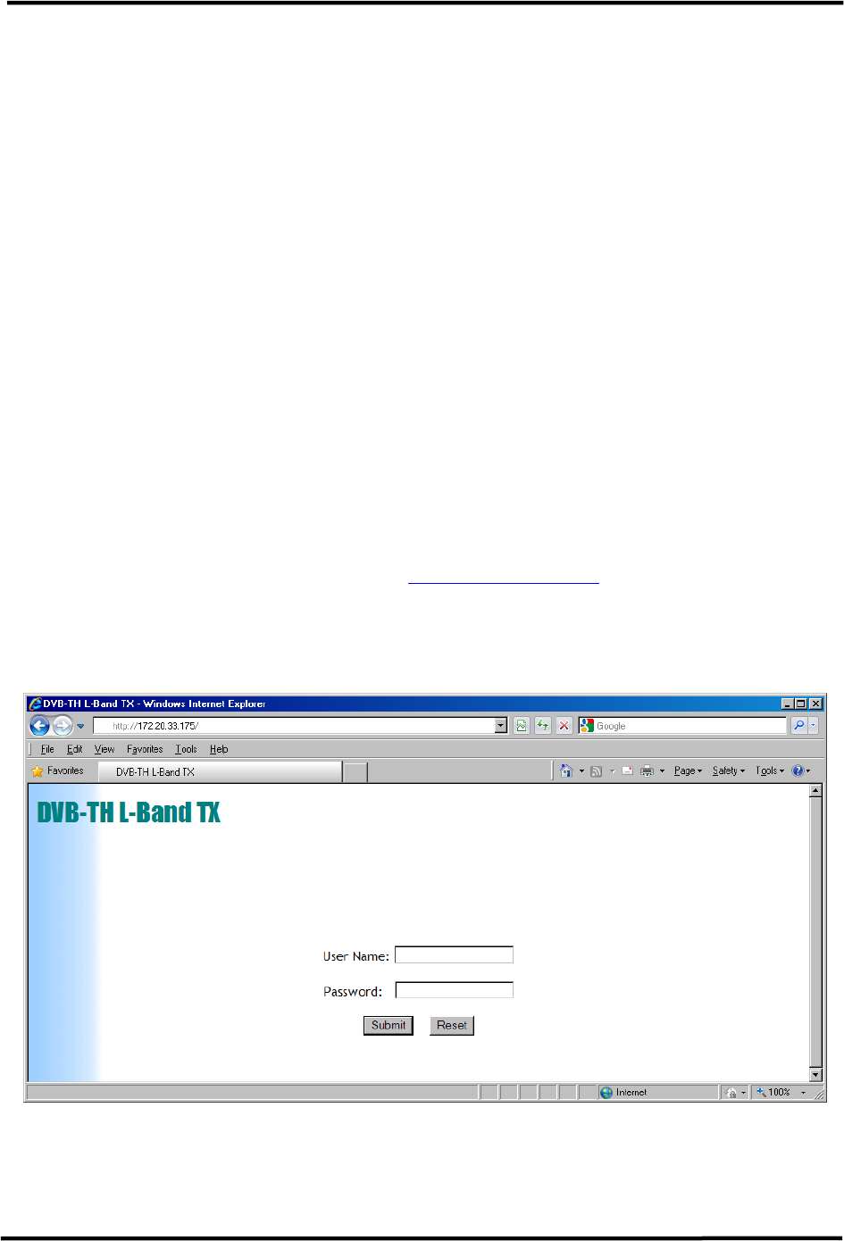
CL1TC-4 400W DVB-H Transmitter WEB Interface
Product Manual, Rev. 1 49
6 Web GUI Interface
6.1 Introduction
The transmitter parameters can be reviewed or changed using the Web GUI Interface. The
Web GUI interface is an intuitive interface allowing the user to access the current
transmitter status and set up the operational parameters of the transmitter. The Web GUI
interface uses a simple hierarchical menu structure which provides access to the transmitter
parameters.
The modulator needs to be assigned an IP address in order to access the Web GUI. The
transmitter is shipped from the factory with a default IP address of 172.20.33.69, but the
user will need to modify the IP address of each unit according to the local network. The IP
address can be accessed and modified from the console interface (CLI) or front panel
interface.
6.2 Access and Navigation
6.2.1 Login
Connect either locally or remotely via the modulator Ethernet port:
• Open a web browser window (e.g., Internet Explorer, Firefox, etc.) and enter the
modulator IP address. For example: http://172.20.33.69/
• The first menu page is the login page.
• The User Name field must be kept blank, while the default password for normal
access is “admin”.
Figure 6-1 Login Screen
Once the user successfully logs in, the Global status page is displayed. This page provides
global status information for the transmitter system.
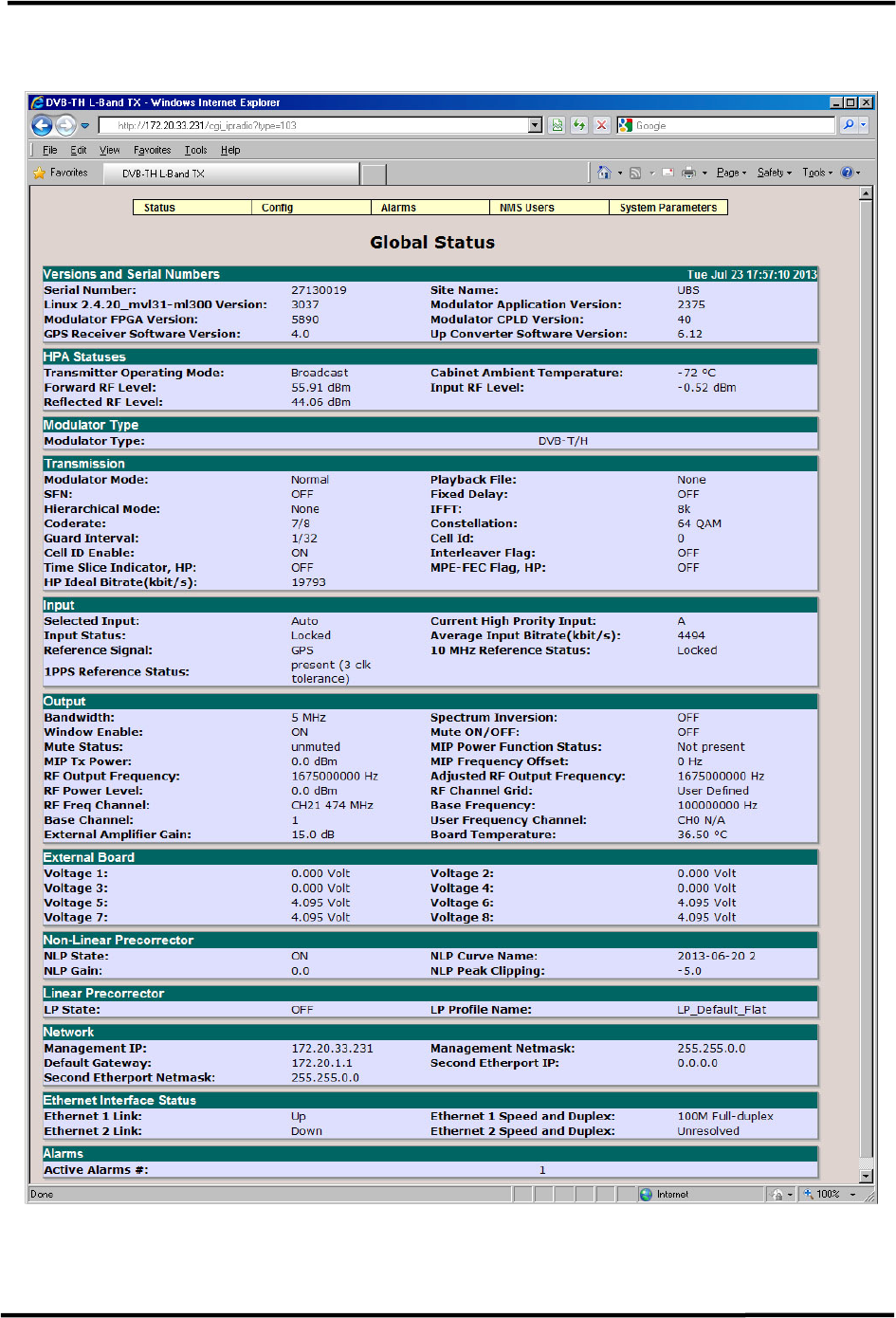
CL1TC-4 400W DVB-H Transmitter WEB Interface
Product Manual, Rev. 1 50
6.2.2 Global Status Page
Figure 6-2 Transmitter Global Status Page (MFN Mode)

CL1TC-4 400W DVB-H Transmitter WEB Interface
Product Manual, Rev. 1 51
6.2.3 GUI Navigation and Structure
The Global Status page seen in Figure 6-2 demonstrates the hierarchical structure of the
Web GUI interface. Along the top of the screen are a row of five icons with pull down
menus. The five menu categories accessible via the Web GUI interface are:
1) Status – Displays the current operating status of the transmitter
2) Config – Provides access to change the transmitter operating parameters
3) Alarms – Provides alarm status and settings as well as alarm log information
4) NMS Users – Set user(s) log in authorization, passwords and other information
5) System Parameters – Set access control, network and SNMP parameters as well as
system reset and software upgrades
The menu tree for the Web GUI is shown below:
Status Config Alarms NMS Users
System
Parameters
Æ Æ Æ Æ Æ
Global Status Modulator
Mode
Alarm
Properties
User
Properties
Identification
GPS Status Transmission External
Voltage Alarm
Setting
Access
Control
HPA Input Log
Management
Network
Parameters
Output Alarm Log SNMP
Parameters
RF Channels System Time
User RF
Channels
Heartbeat
Time
Non-linear
Pre-corrector
System Reset
Linear
Pre-corrector
Download
Config Files(s)
HPA Control Upgrade and
Files Upload
GPS List Uploaded
Files
Site
Table 6-1 Web GUI Menu Structure
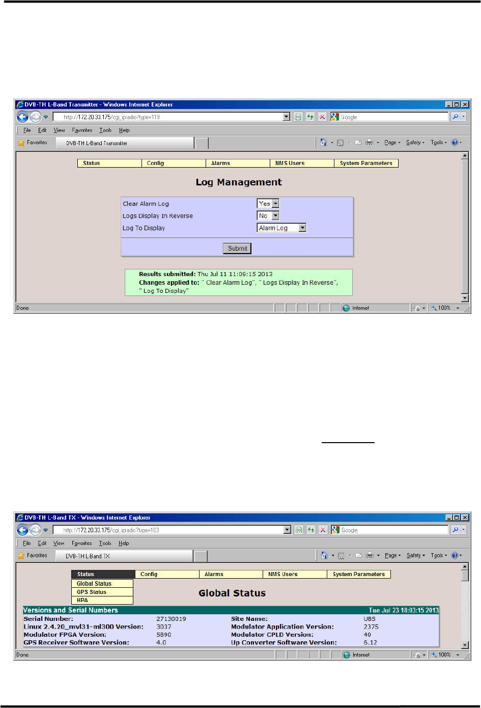
CL1TC-4 400W DVB-H Transmitter WEB Interface
Product Manual, Rev. 1 52
6.2.4 Changing Parameters
Before changes to system parameters are accepted, the user must first click the submit
button. The example below has the user clearing the Alarm Log in the Log Management
screen.
Figure 6-3 Example of Submitting a Parameter Change
Once the user has selected “Yes” for the Clear Alarm Log pull down box, the user will then
need to click Submit. At that time a small green box will appear at the bottom of screen
confirming the change.
6.3 Status Menu
The Status menu contains the following pull-down items (see Figure 6-4 below).
• Global Status
• GPS Status
• HPA
Figure 6-4 Status Menu

CL1TC-4 400W DVB-H Transmitter WEB Interface
Product Manual, Rev. 1 53
6.3.1 Global Status
The Global status page appears upon login and provides general information about
parameter settings and the transmitter’s alarm status. The list of parameters will change
dynamically as the transmission mode (MFN or SFN) and/or transport stream input (ASI or
IP) is changed. See Figure 6-2, Figure 6-5 and Figure 6-6 for details.
The drop down menus, located at the top of the status page, provide links to other pages
that control various parameters and alarm functions.
• Versions and Serial Numbers: Displays the software and firmware version number
for each of the main software components of the modulator.
• HPA Statuses: Displays the Transmitter Operating Mode (Broadcast, Standby or
Manual) Input, Forward and Reflected RF power levels for the HPA as well as the
Cabinet Ambient Temperature.
• Modulator Type: Displays the modulator waveform selected (DVB-T/H).
• Transmission: Displays the Modulator Mode (Normal or CW), the SFN status (ON
or OFF), the OFDM parameter settings and the Ideal Bit Rate. The statuses of the
MIP offset functions are only displayed when SFN mode is enabled.
• SFN Parameters: Displays the Transmitter ID, the Local Delay Offset set by the
user, the MIP Maximum delay and MIP Time offset as included in the MIP and the
resulting Adjusted SFN Delay. This window is only available when SFN mode is
enabled.
• Input: Displays the Selected Input (Auto, A, B or IP), Input Status (Locked or
Unlocked) and the status of the 10 MHz and 1PPS Reference inputs.
• IP Input: Displays the IP Input status, Input Stream Destination IP Address and
Port, Buffer Depth, Packet Size, FEC Mode, Input Bit Rate and Packet information.
This window is only available when an IP input has been selected.
• Output: Displays the Bandwidth, RF Output Frequency, RF Output Power Level,
Spectrum Inversion (ON or OFF), parameters related to the pre-defined and User
Channel Grids (not uses for this application) as well as MIP parameters.
The Mute setting (ON or OFF) and Mute status (Muted or Unmuted) are also
displayed. The output might be muted as a result of an active alarm, even though
the Mute setting is set to OFF.
• External Board: Displays the voltage on each of the I/O port pins.
• Non-Linear Pre-corrector: Displays the status of the Non-linear Pre-corrector.
• Linear Pre-corrector: Displays the status of the Linear Pre-corrector.
• Network: Displays the modulator IP Addresses, Default Gateway and the
Management Netmask.
• Ethernet Interface Status: Displays the link status and speed.
• Alarms: Displays the number of active alarms
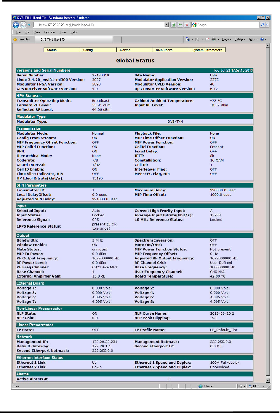
CL1TC-4 400W DVB-H Transmitter WEB Interface
Product Manual, Rev. 1 54
Figure 6-5 Transmitter Global Status Page (SFN Mode, ASI Input)
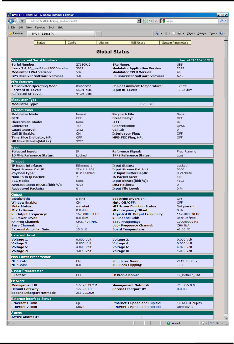
CL1TC-4 400W DVB-H Transmitter WEB Interface
Product Manual, Rev. 1 55
Figure 6-6 Transmitter Global Status Page (MFN Mode, IP Input)
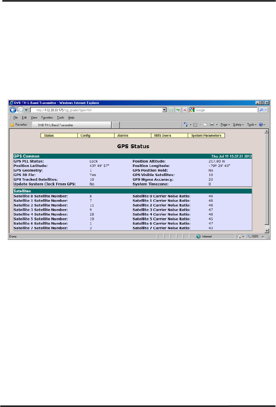
CL1TC-4 400W DVB-H Transmitter WEB Interface
Product Manual, Rev. 1 56
6.3.2 GPS Status
The GPS Status page provides access to GPS receiver information including the lock status
and the number of visible satellites, as well as the exact location and time.
• GPS Common: Indicates the GPS PLL Status (Lock or Unlock), Position Altitude,
Position Latitude, Position Longitude, 3D Fix, Number of Visible and Tracked
Satellites, and Sigma Accuracy. GPS Common will also indicate if the System Clock
is updated from the GPS and it will display the System Timezone.
• Satellites: Indicates the satellite number and corresponding carrier to noise ratio.
Figure 6-7 GPS Status
After initialization, the GPS starts tracking the satellites to determine its position; the
accuracy of the GPS output signals depends on the GPS satellite reception. The GPS PLL
Status will indicate “Lock” when the quality of the received GPS signals are higher than the
minimum reception level and the minimum number of tracked satellites is reached. GPS 3D
Fix will occur when a minimum of 4 satellites are tracked. The GPS will then display Position
Latitude, Longitude and Altitude.
The output of the GPS (1 PPS and 10 MHz pulses) is fed to the Distribution Amplifiers, which
in turn feed the pulses to the modulator and up-converter.
The Controller communicates continuously with the GPS to deter-mine if the GPS is still
operating correctly and still receiving the satellite signals, etc., or if it has any alarm
(malfunction) to report.
A PLL (Phase Locked Loop) Status Unlocked event can be the result of an antenna under-
current (antenna open) or antenna over-current (short), a poor GPS 3D Fix (minimum
requirement is 4 satellites). In general, conditions that result in a poor GPS signal quality.
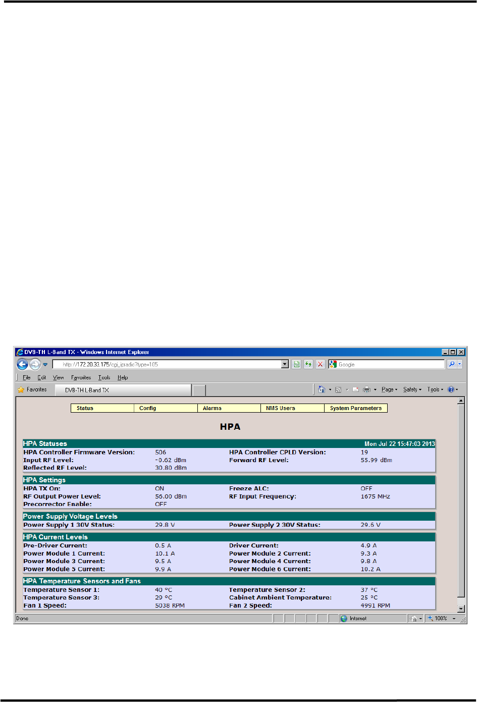
CL1TC-4 400W DVB-H Transmitter WEB Interface
Product Manual, Rev. 1 57
6.3.3 HPA
The HPA page provides access to HPA information including the HPA TX On status (On of
Off), Input, Forward and Reflected power levels as well as sub-module current values and
heat sink temperature values.
• HPA Statuses: Displays the HPA Controller Firmware and CPLD versions as well as
the Input, Forward and Reflected RF (power) levels.
• HPA Settings: Displays the HPA Tx On status (ON or OFF), RF Output Power Level
(target), Precorrector Enable (OFF), Freeze ALC (ON or OFF) and RF Input
Frequency.
• Power Supply Voltage Levels: Displays the DC voltage for HPA Power Supply 1
and HPA Power Supply 2.
• HPA Current Levels: Displays the current consumption for the Pre-Driver, Driver
and Power Modules.
• HPA Temperature Sensors and Fans: Displays the temperature readings for the
Pre-Driver and Power Module heat sink temperature sensors as well as the fan speed
for the front panel fans.
• Temperature Sensor 1 – Power Module heat sink
• Temperature Sensor 2 – Power Module heat sink
• Temperature Sensor 3 – Pre-Driver heat sink
Figure 6-8 HPA
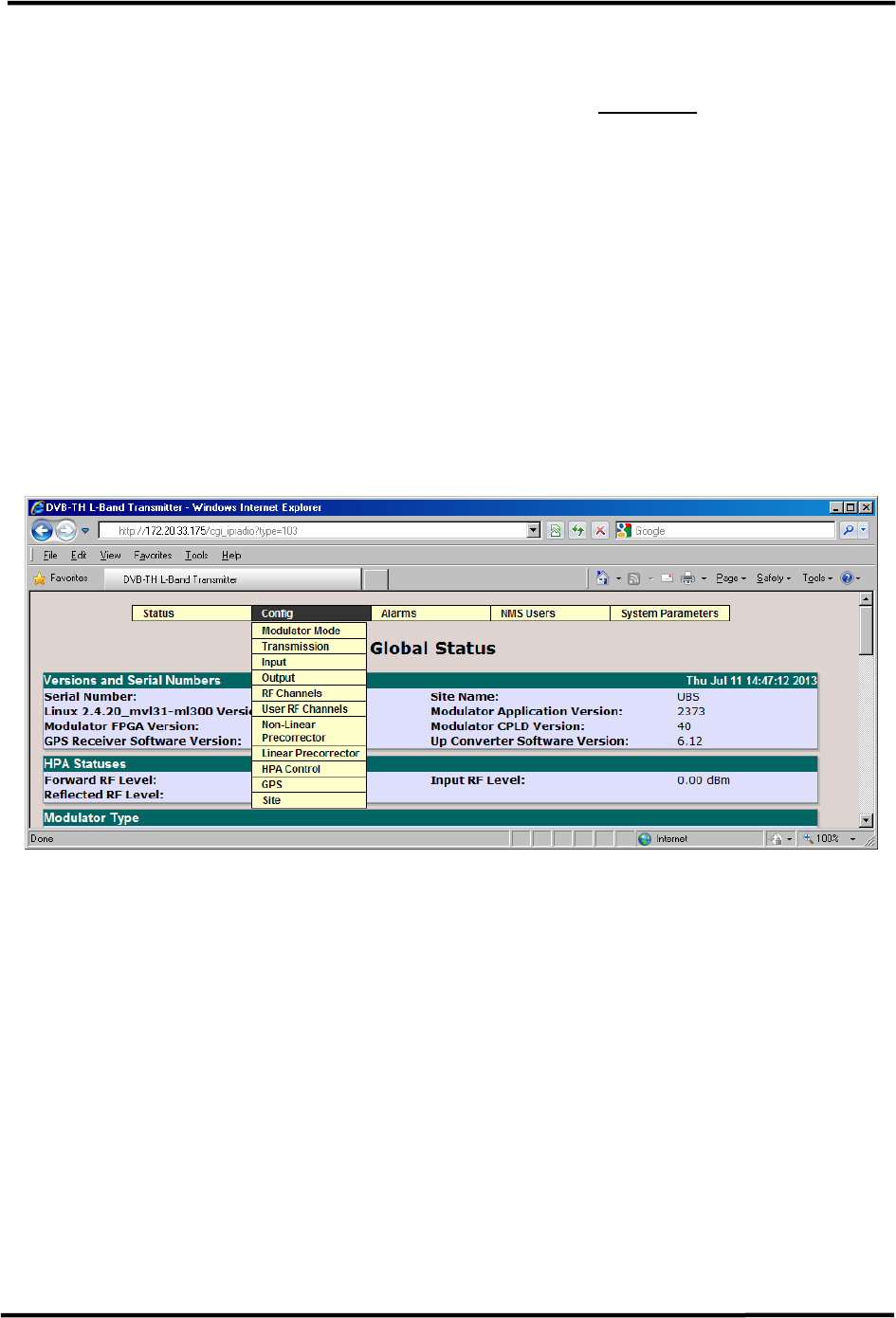
CL1TC-4 400W DVB-H Transmitter WEB Interface
Product Manual, Rev. 1 58
6.4 Config Menu
The Config menu contains the following pull-down items (see Figure 6-9 below).
• Modulator Mode
• Transmission
• Input
• Output
• RF Channels
• User RF Channels
• Non-Linear Precorrector
• Linear Precorrector
• HPA Control
• GPS
• Site
Figure 6-9 Config Menu
The Configuration menu provides access to change the transmitter operating parameters.
The operating parameters and their range of values or settings are also accessible through
the CLI interface and modulator front panel interface.
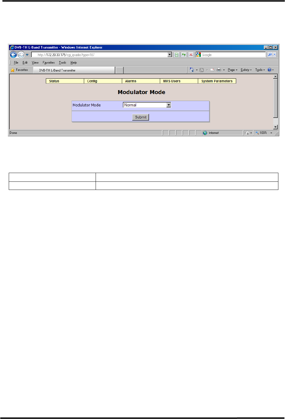
CL1TC-4 400W DVB-H Transmitter WEB Interface
Product Manual, Rev. 1 59
6.4.1 Modulator Mode
This page allows the users to select the Modulator Mode and the Test Mode.
Figure 6-10 Modulator Mode Configuration
The available parameters are:
Item Option
Modulator Mode Normal, CW, Test1 (Carriers Removal), Record , Playback
Table 6-2 Modulator Mode Parameters
CW and Test 1 are special test modes not used in regular operation. The CW mode
generates a narrow-band frequency tone. This is useful for phase noise measurements or
to view background noise. The Test 1 mode suppresses a subset of the carriers from the
center of the DVB-H signal. This is useful for simulating a notch fading event or to view the
background noise present in the band. In the “Test 1” mode, usually 500 carriers are
removed. The number of removed carriers can be factory configured from between 100 to
800 via the advanced access interface.
The Record mode allows the user to record a input data stream (limit of 16 megabytes) for
later playback. The modulator must first be set to SFN mode, a valid SFN input stream
must be present and no input stream alarms can be reported.
After recording, the modulator will automatically switch back to Normal mode. The user can
check the Global Status page to see that the modulator is back in Normal mode and that the
stream has been recorded. The user can check also the “List Uploaded Files” screen under
“System Parameters” to see the file name displayed.
In the Playback mode the recorded input stream is used to generate a modulator output.
This is useful for detailed system testing especially when an input signal is not available or
for benchmark testing using a known test signal.
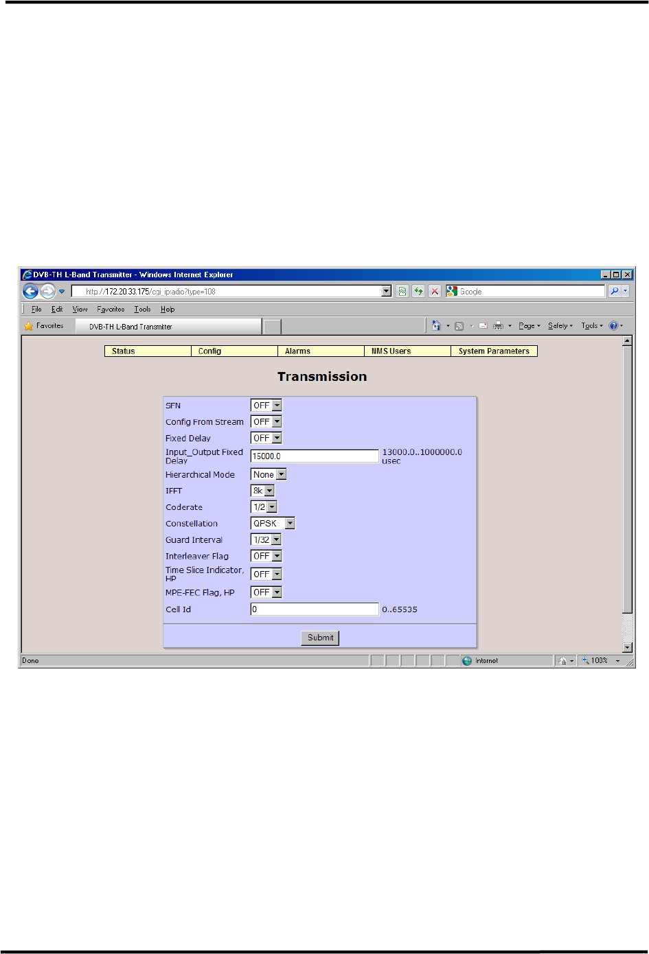
CL1TC-4 400W DVB-H Transmitter WEB Interface
Product Manual, Rev. 1 60
6.4.2 Transmission
The Transmission page allows the user to select the network type (MFN or SFN), set the
modulation parameters and configure a number of SFN parameters.
The Transmission page will change dynamically, depending on the Modulator Mode selected
(MFN, SFN or SFN with Config From Stream On). The user has the option to configure the
modulation parameters from the incoming stream (MIP) or locally.
In SFN mode, a network of modulator operating at the same frequency are all synchronized
using special timing packets (MIP) embedded in the input transport stream as well as GPS
timing information. If the SFN mode is disabled, the system will operate in MFN mode
where all modulators in a network work independently of one another.
Figure 6-11 Transmission Configuration (MFN)
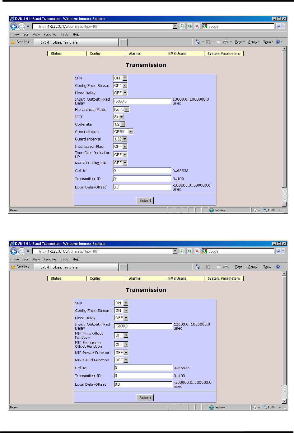
CL1TC-4 400W DVB-H Transmitter WEB Interface
Product Manual, Rev. 1 61
Figure 6-12 Transmission Configuration (SFN – No Config from Stream)
Figure 6-13 Transmission Configuration (SFN – Config from Stream)

CL1TC-4 400W DVB-H Transmitter WEB Interface
Product Manual, Rev. 1 62
The available parameters for MFN and SFN mode are:
Item Option
SFN OFF, ON
Config From Stream ON, OFF
If “Config From Stream” is ON, the modulation
parameters are set from the input SFN data stream and
the other modulation parameters of this web-page are
ignored. If it is set to OFF, the modulation parameters
can be configured locally.
Only relevant when SFN is enabled.
Fixed Delay OFF, ON
If “Fixed Delay” is ON, the output stream will be
synchronized to the input stream.
Only relevant when an ASI input is present.
Input_Output Fixed Delay Range: 13000 μsec .. 1 second
Only relevant when an ASI input is present.
Hierarchical Mode None, aEq1, aEq2, aEq4
IFFT 2k, 8k, 4k
Coderate 1/2, 2/3, 3/4, 5/6, 7/8
Constellation QPSK, 16 QAM, 64 QAM
Guard Interval 1/32, 1/16, 1/8, 1/4
Interleaver Flag OFF, ON
Only relevant for a 2k and 4k IFFT.
Time Slice Indicator, HP OFF, ON
MPE-FEC Flag, HP OFF, ON
Cell ID Range: 0 .. 65535
Transmitter ID Range: 0 .. 100
Only relevant when SFN is enabled.
Local Delay Offset Range: -500000.0 .. +500000.0 μsec
Only relevant when SFN is enabled.
Table 6-3 Transmission Parameters (MFN and SFN Mode)

CL1TC-4 400W DVB-H Transmitter WEB Interface
Product Manual, Rev. 1 63
The available parameters for SFN mode with Config From Stream On are:
Item Option
SFN OFF, ON
Config From Stream ON, OFF
Fixed Delay OFF, ON
Input_Output Fixed Delay Range: 13000 μsec .. 1 second
MIP Time Offset Function OFF, ON
MIP Frequency Offset
Function
OFF, ON
MIP Power Function OFF, ON
MIP Cell ID Function OFF, ON
Cell ID Range: 0 .. 65535
Transmitter ID Range: 0 .. 100
Local Delay Offset Range: -500000.0 .. +500000.0 μsec
Table 6-4 Transmission Parameters (SFN Mode with Config From Stream On)
All of the above parameters are described in the DVB-TH standard. The above list includes
a number of optionalMIP parameters for remote adjustment of the transmitter signal:
• MIP Time Offset Function (tx_time_offset_function)
The tx_time_offset_function is used to apply a deliberate offset in time of the
transmitted DVB-TH signal, relative to the reference transmission time
(STS+maximum_delay) modulo 107
• MIP Frequency Offset Function (tx_frequency_offset_function)
The tx_frequency_offset_function is used to apply a deliberate frequency offset of
the centre frequency of the emitted DVB-TH signal relative to the centre frequency of
the RF channel.
• MIP Power Function (tx_power_function)
The tx_power_function can be used to remotely configure the transmitter ERP.
• MIP CellId Function (cell_id_function)
The cell_id_function can be used to configure the cell identifier of the transmitter.
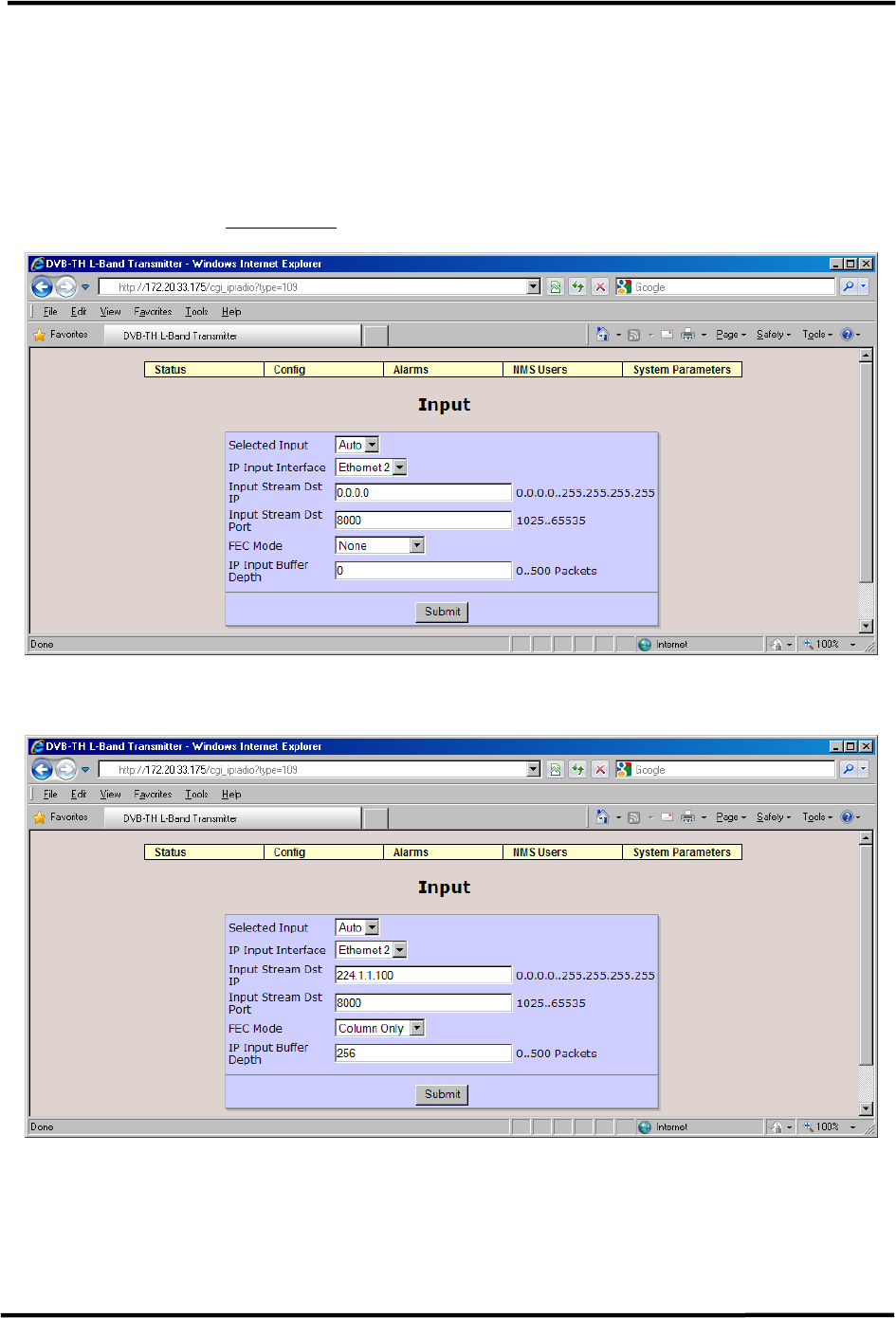
CL1TC-4 400W DVB-H Transmitter WEB Interface
Product Manual, Rev. 1 64
6.4.3 Input
The Input page allows the user to select ASI port A, ASI port B, Auto selection between ASI
ports or an IP input.
To configure the modulator with an IP (GbE TS) input, the user must set the Selected Input
to IP Input and configure the IP Input Interface, Input Stream Dst IP and Input Stream Dst
Port accordingly – see Figure 6-15.
Figure 6-14 ASI Input Configuration
Figure 6-15 IP Input Configuration

CL1TC-4 400W DVB-H Transmitter WEB Interface
Product Manual, Rev. 1 65
The available parameters are:
Item Selection
Selected Input A, B, Auto, IP
Choice of ASI port A, ASI port B, Auto selection between
ASI ports or an IP input.
IP Input Interface Ethernet 1, Ethernet 2
If Selected Input is set to IP this will determine which
Ethernet port is selected for the input stream.
Input Stream Dst IP Standard IP address: 0.0.0.0..255.255.255.255
Relevant only if Selected Input is set to IP and Fixed
Delay is OFF.
Input Stream Dst Port Range: 1025 .. 65535
Relevant only if Selected Input is set to IP and Fixed
Delay is OFF.
FEC Mode None, Column Only, Column + Row
Relevant only if Selected Input is set to IP and Fixed
Delay is OFF. This sets the Forward error Correction
(FEC) mode for the IP input as per the Pro MPEG CoP#3
standard for FEC protection of MPEG-2 transport streams
over an IP network.
IP Input Buffer Depth Range: 0 .. 500 Packets
Relevant only if Selected Input is set to IP and Fixed
Delay is OFF.
Table 6-5 Input Parameters
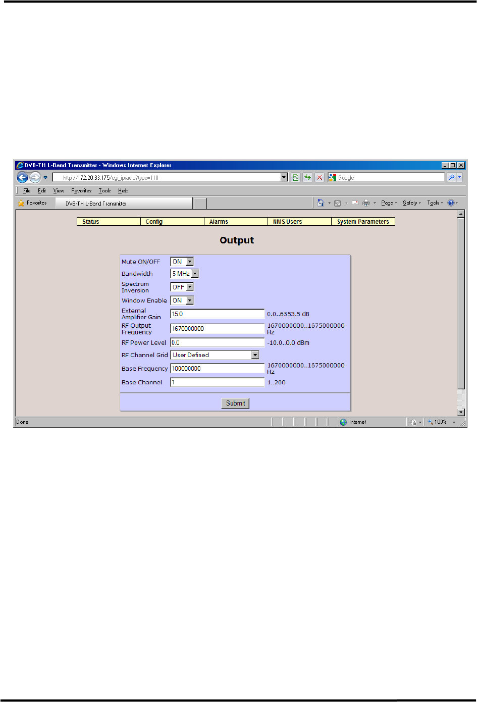
CL1TC-4 400W DVB-H Transmitter WEB Interface
Product Manual, Rev. 1 66
6.4.4 Output
The Output page allows the user to Mute the modulator output, set the Spectrum Inversion
and modify the RF Output Frequency and the modulator RF Power Level.
The menu options vary depending if the system is configured for SFN with “Config From
Stream” enabled or MFN operation (see section 6.4.2). When the system is in MFN mode
the user can select the transmission bandwidth. If “Config From Stream” is enabled when
SFN mode is enabled, the bandwidth option is not available. The next two figures show the
Output configuration screen for both MFN and SFN operation.
Figure 6-16 Output Configuration (MFN Mode)
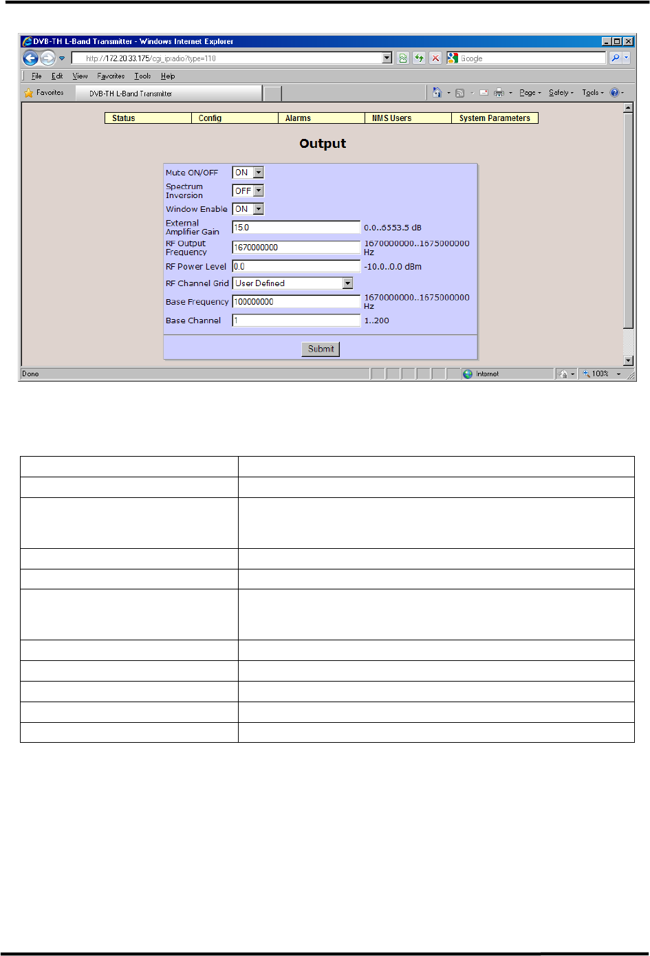
CL1TC-4 400W DVB-H Transmitter WEB Interface
Product Manual, Rev. 1 67
Figure 6-17 Output Configuration (SFN Mode – Config From Stream On)
The available parameters are:
Item Selection
Mute ON/OFF OFF, ON
Bandwidth 5 MHz
Bandwidth selection is only available in MFN mode
Spectrum Inversion OFF, ON
Window Enable OFF, ON
External Amplifier Gain Range: 0.0.. 6553.5 dB
Is used for the MIP power function.
RF Output Frequency Range: 167000000 .. 167500000 Hz
RF Power Level Range: -10.0 .. 0.0 dBm
RF Channel Grid DVBT UHF 8M 474-858 MHz, User Defined
Base Frequency Range: 167000000 .. 167500000 Hz
Base Channel Range: 1 .. 200
Table 6-6 Output Parameters
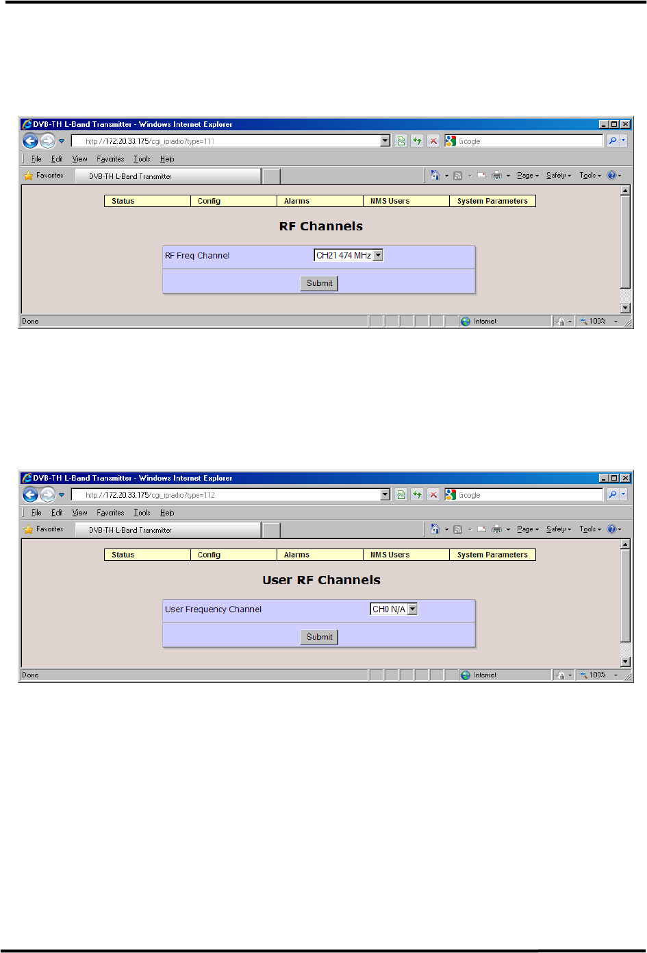
CL1TC-4 400W DVB-H Transmitter WEB Interface
Product Manual, Rev. 1 68
6.4.5 RF Channels
Note: RF Channels is not used for this application and should not be modified by
the user.
Figure 6-18 RF Channels Configuration
6.4.6 User RF Channels
Note: User RF Channels is not used for this application and should not be modified
by the user.
Figure 6-19 User RF Channels Configuration
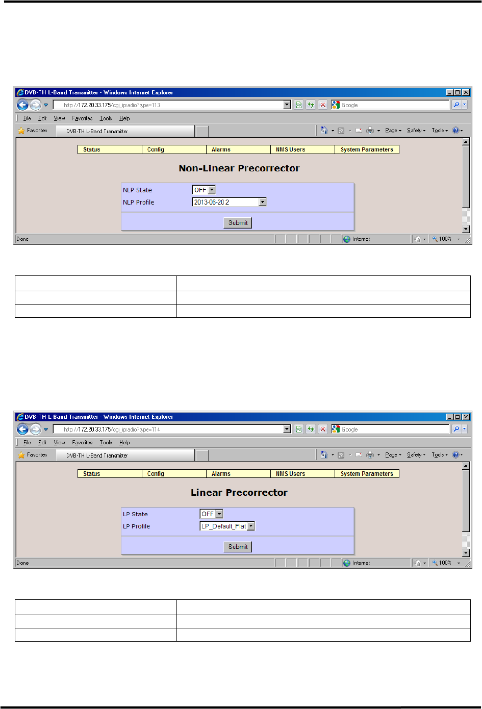
CL1TC-4 400W DVB-H Transmitter WEB Interface
Product Manual, Rev. 1 69
6.4.7 Non-Linear Pre-corrector
This page allows the user to select the NLP (Non-Linear pre-corrector) Profile state and
profile.
Figure 6-20 Non-Linear Pre-corrector Configuration
Item Selection
NLP State OFF, ON
NLP Profile A selection of different NLP profile files
Table 6-7 Non-Linear Pre-corrector Parameters
6.4.8 Linear Pre-corrector
This screen pages the user to select the LP (Linear pre-corrector) State and profile.
Figure 6-21 Linear Pre-corrector Configuration
Item Selection
LP State OFF, ON
LP Profile A selection of different LP profile files
Table 6-8 Linear Pre-corrector Parameters
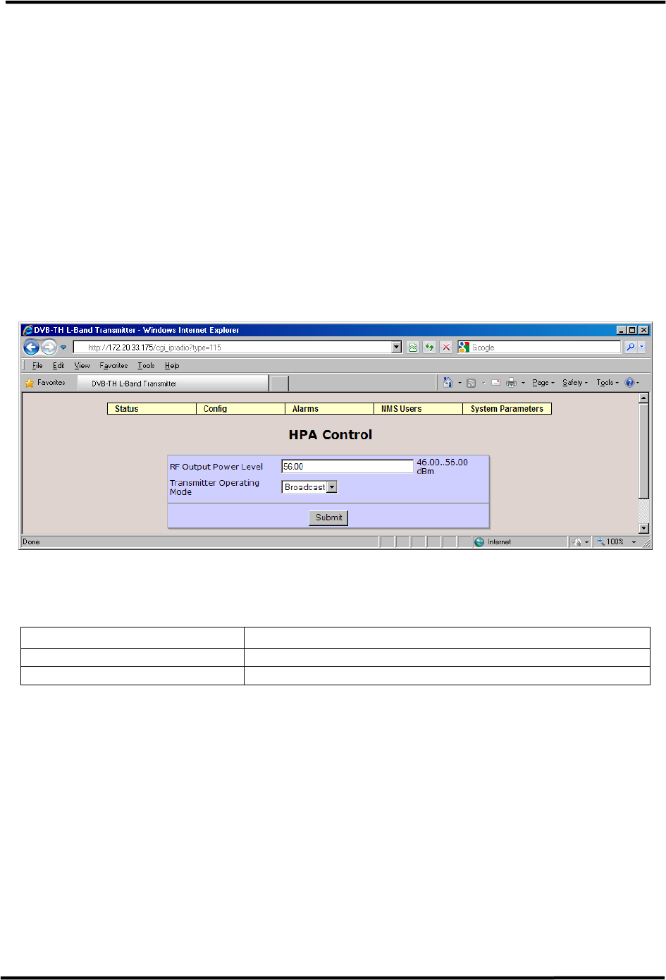
CL1TC-4 400W DVB-H Transmitter WEB Interface
Product Manual, Rev. 1 70
6.4.9 HPA Control
The HPA Control page contains a drop down menu that allows the user to set the
transmitter to one of the following modes:
• Standby
• Broadcast
• Manual
Broadcast mode represents normal operation. Standby mode disables the transmitter
output. In Manual mode the HPA behaves as a simple amplifier and the modulator control
of the HPA output is limited to setting the input drive level to the HPA.
The RF Output Power Level allows the user to set the output power level to a value between
46 dBm and 56 dBm.
Figure 6-22 HPA Control Configuration
The available parameters are:
Item Selection
RF Output Power Level Range: 46.00 .. 56.00 dBm
Transmitter Operating Mode Standby, Broadcast, Manual
Table 6-9 Non-Linear Pre-corrector Parameters
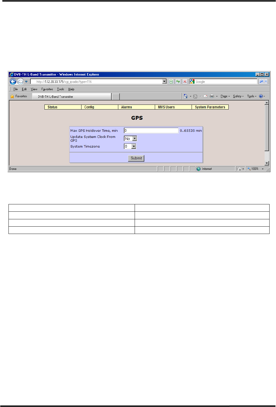
CL1TC-4 400W DVB-H Transmitter WEB Interface
Product Manual, Rev. 1 71
6.4.10 GPS
The most important parameter for the GPS menu is the Max GPS Holdover Time parameter.
Following a loss of signal lock to the GPS satellite network, the Max GPS Holdover time is
the maximum length of time the system will continue to operate in a free-running mode
before an alarm is issued leading to a possible transmitter shutdown condition. It is
imperative for a SFN network for all transmitters to be synchronized to GPS at all times.
Figure 6-23 GPS Configuration
The available parameters are:
Item Option
Max GPS Holdover Time, min Range: 0 .. 65535 min
Update System Clock From GPS No, Yes
System Timezone -11 to 11 hours
Table 6-10 GPS Parameters