UBS Axcera CL1TC-4 400-Watt, 1.6 GHz DVB-H Transmitter User Manual 8SC Transmitter
UBS-Axcera 400-Watt, 1.6 GHz DVB-H Transmitter 8SC Transmitter
Contents
- 1. User Manual Part 1
- 2. User Manual Part 2
User Manual Part 2
CL1TC-4 400W DVB-H Transmitter WEB Interface
Product Manual, Rev. 1 72
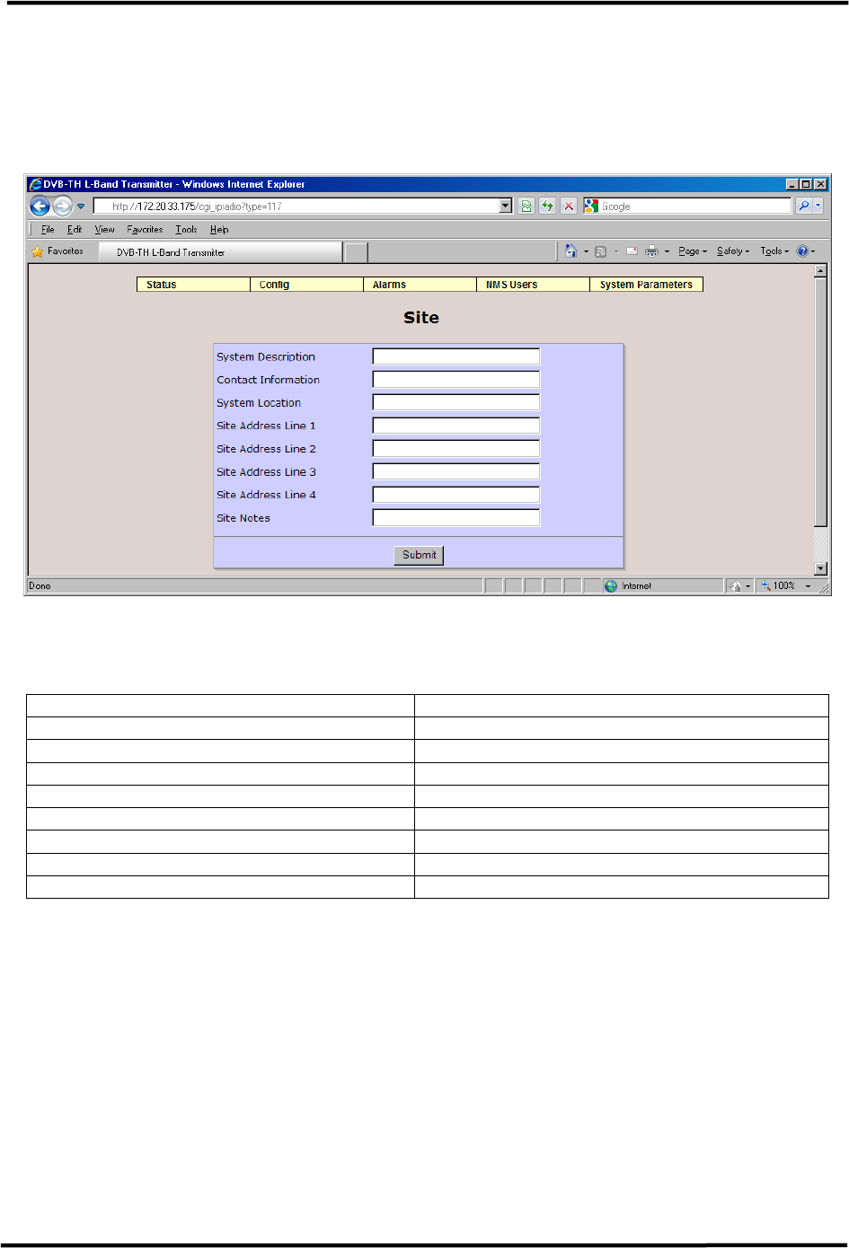
6.4.11 Site
The Site page allows the user to add information identifying the site, including the name of
the site, address, contact information, etc. Each item is limited to 35 alphanumeric
parameters.
Figure 6-24 Site Information
The available parameters are:
Item Option
System Description up to 35 alphanumeric characters
Contact Information up to 35 alphanumeric characters
System Location up to 35 alphanumeric characters
Site Address Line 1 up to 35 alphanumeric characters
Site Address Line 2 up to 35 alphanumeric characters
Site Address Line 3 up to 35 alphanumeric characters
Site Address Line 4 up to 35 alphanumeric characters
Site Notes up to 35 alphanumeric characters
Table 6-11 Site Parameters
CL1TC-4 400W DVB-H Transmitter WEB Interface
Product Manual, Rev. 1 73
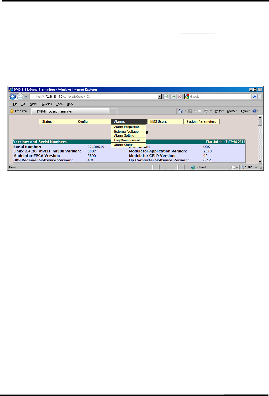
6.5 Alarms Menu
The Alarms menu contains the following pull-down items (see Figure 6-25 below):
• Alarm Properties
• External Voltage Alarm Setting
• Log Management
• Alarm Log
Figure 6-25 Alarms Menu
The Alarms menu allows the user to set the properties of each alarm including system
actions as well to view alarm and event logs.
CL1TC-4 400W DVB-H Transmitter WEB Interface
Product Manual, Rev. 1 74
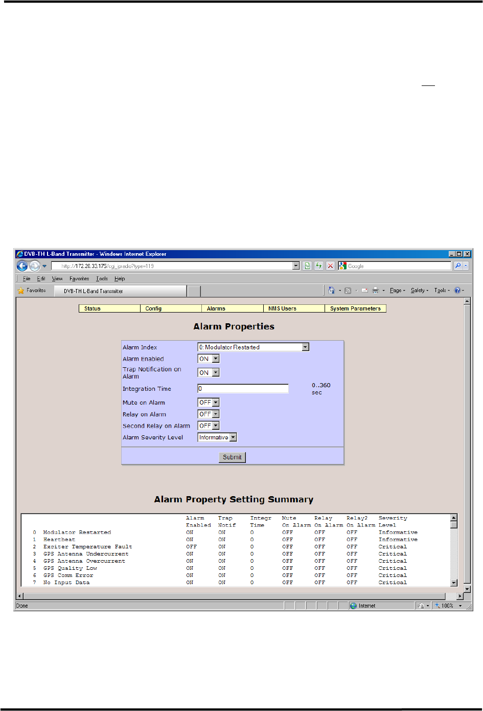
6.5.1 Alarm Properties
The first item in the Alarm Properties page is the Alarm Index. The Alarm Index box has a
pull-down menu permitting the user to select a specific alarm from the list for configuration.
The list of alarms along with a description of each alarm can be found in Section 10.
The user can configure each alarm to be displayed (Alarm Enabled ON) or ignored (Alarm
Enabled OFF) and can configure the modulator to send an SNMP trap for any active alarm.
The user can also configure a number of relays on the modulator rear panel to be triggered
on alarm.
The integration time can be set to any value between 0 to 360 seconds, allowing the
modulator to avoid reporting intermittent alarms. An alarm will only be reported if it is still
active after the integration time has elapsed.
The Alarm Properties page also summarizes the current Alarm Properties settings for all
system alarms under Alarm Property Setting Summary.
Figure 6-26 Alarm Properties Configuration

CL1TC-4 400W DVB-H Transmitter WEB Interface
Product Manual, Rev. 1 75
For each alarm, the user can set the following:
Item Option
Alarm Enabled OFF, ON
Used to control whether the selected alarm will be
displayed (ON) or ignored (OFF).
Trap Notification on Alarm OFF, ON
Used to control whether the selected alarm will
produce a SNMP trap notification.
Integration Time 0 to 360 sec
Length of time an alarm condition is present before
the alarm is declared.
Mute on Alarm OFF, ON
Used to control whether the selected alarm will mute
the transmitter output.
Relay on Alarm OFF, ON
Used to control whether the selected alarm will active
the first alarm relay.
Second Relay on Alarm OFF, ON
Used to control whether the selected alarm will active
the second alarm relay.
Alarm Severity Level Critical, Warning, Informative, Cleared
Table 6-12 Alarm Properties Parameters
CL1TC-4 400W DVB-H Transmitter WEB Interface
Product Manual, Rev. 1 76
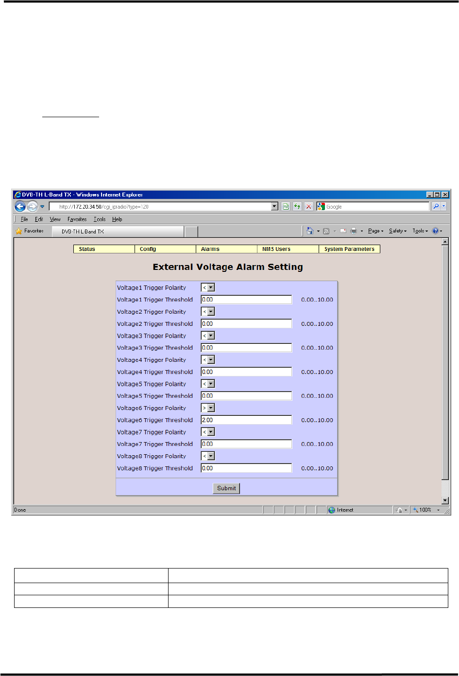
6.5.2 External Voltage Alarm Setting
The External Voltage Alarm Setting page allows the user to set the voltage threshold for
each of the I/O port analog inputs (pins). Voltage 1 though Voltage 8 correspond to pins 1
though 8; pin 9 is ground.
For example, the pin 6 settings (Voltage6 Trigger Polarity and Voltage6 Trigger Threshold)
seen in Figure 6-27 will create an alarm if the pin 6 output voltage is greater than 2.0 VDC.
NOTE: For this application, Pin 6 has been connected to the cabinet door switch contacts,
Pin 7 has been connected to the cabinet smoke detector and the Web interface has been
configured accordingly. The External Voltage Alarm Settings should not be modifies by the
user.
Figure 6-27 External Voltage Alarm Setting Configuration
For each I/O pin, the user can set the following:
Item Selection
Voltage Trigger Polarity <, >
Voltage Trigger Threshold Range: 0.00 .. 10.00
Table 6-13 External Voltage Alarm Setting Parameters
CL1TC-4 400W DVB-H Transmitter WEB Interface
Product Manual, Rev. 1 77
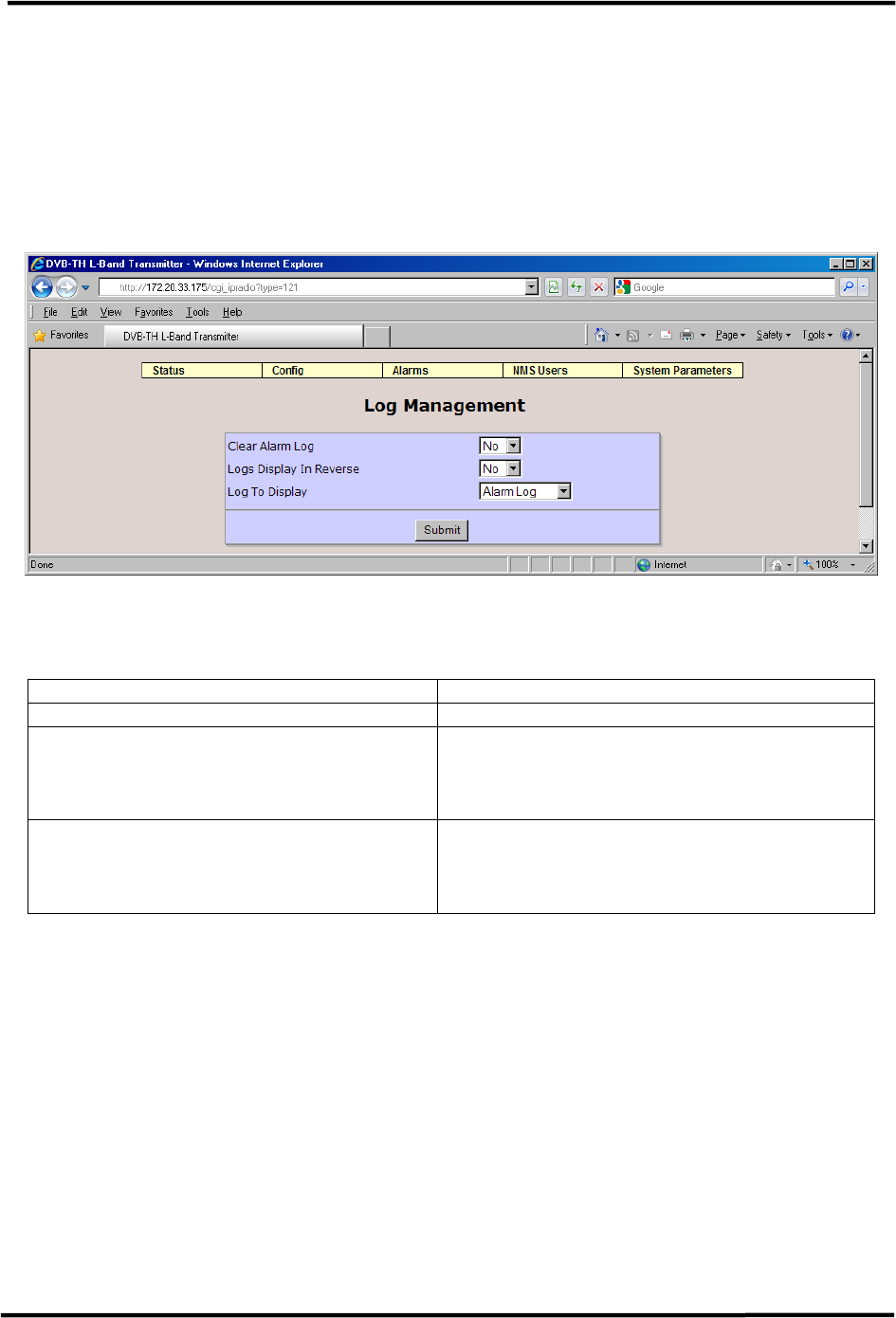
6.5.3 Log Management
The Log Management page can be used to clear the alarm log and/or event log, change the
order alarms appear in the logs and change the displayed alarm log.
If the Alarm Log is configured not to display alarms in reverse, the most recent alarm will be
at the bottom of the list. If the Alarm Log is configured to display alarms in reverse, the
most recent alarm will be at the top of the list.
Figure 6-28 Log Management Configuration
The available parameters are:
Item Option
Clear Alarm Log No, Yes
Logs Display in Reverse No, Yes
Used to determine the order alarms are
displayed in the Alarm Log.
Log To Display Transient Log, Alarm Log
Used to determine if the Alarm Log will
display Transient Alarms or Set Alarms.
Table 6-14 Log Management Parameters
CL1TC-4 400W DVB-H Transmitter WEB Interface
Product Manual, Rev. 1 78
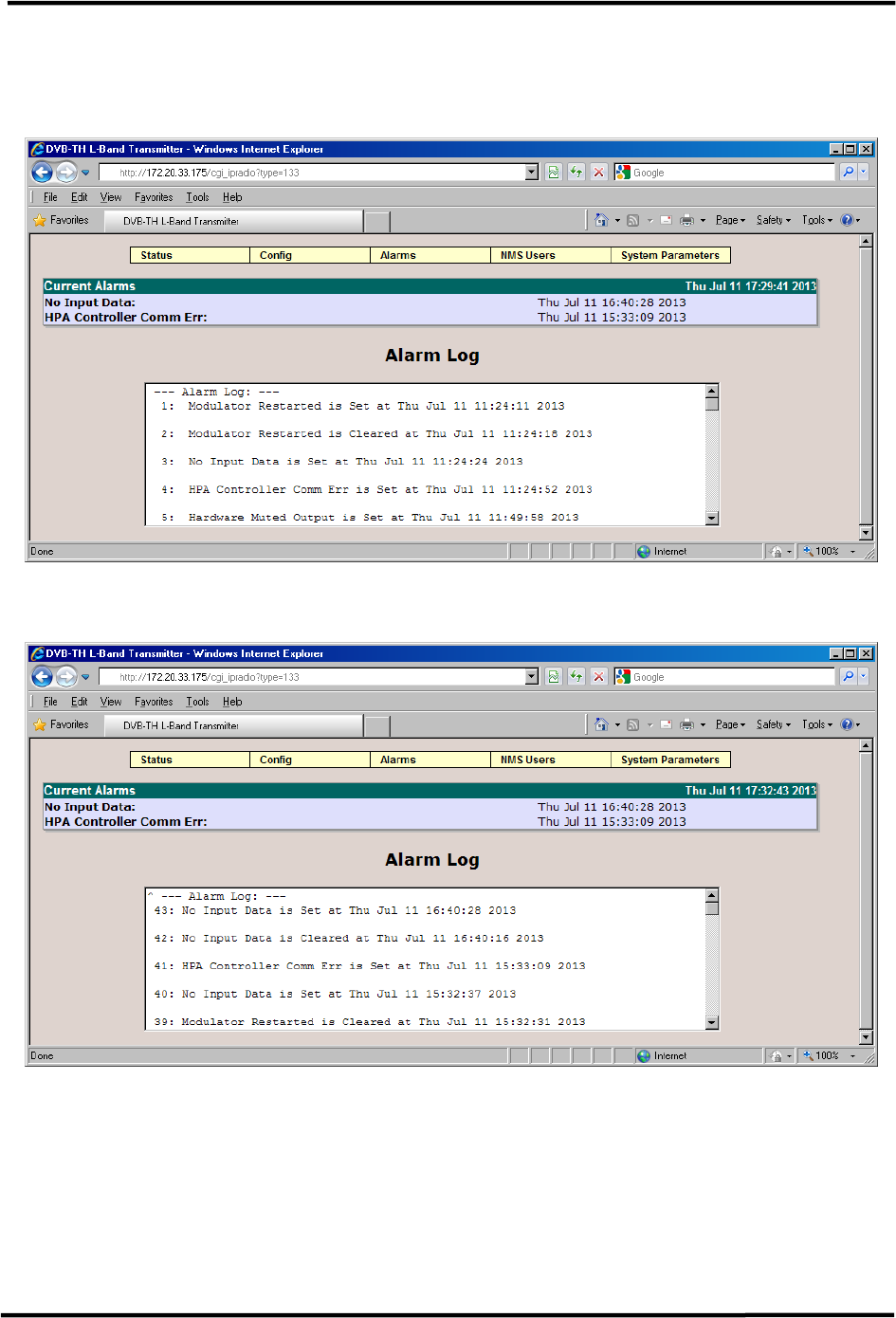
6.5.4 Alarm Log
The Alarm Log lists the current alarms as well as all alarm log entries.
Figure 6-29 Alarm Log
Figure 6-30 Alarm Log (Log Displayed in Reverse)
CL1TC-4 400W DVB-H Transmitter WEB Interface
Product Manual, Rev. 1 79
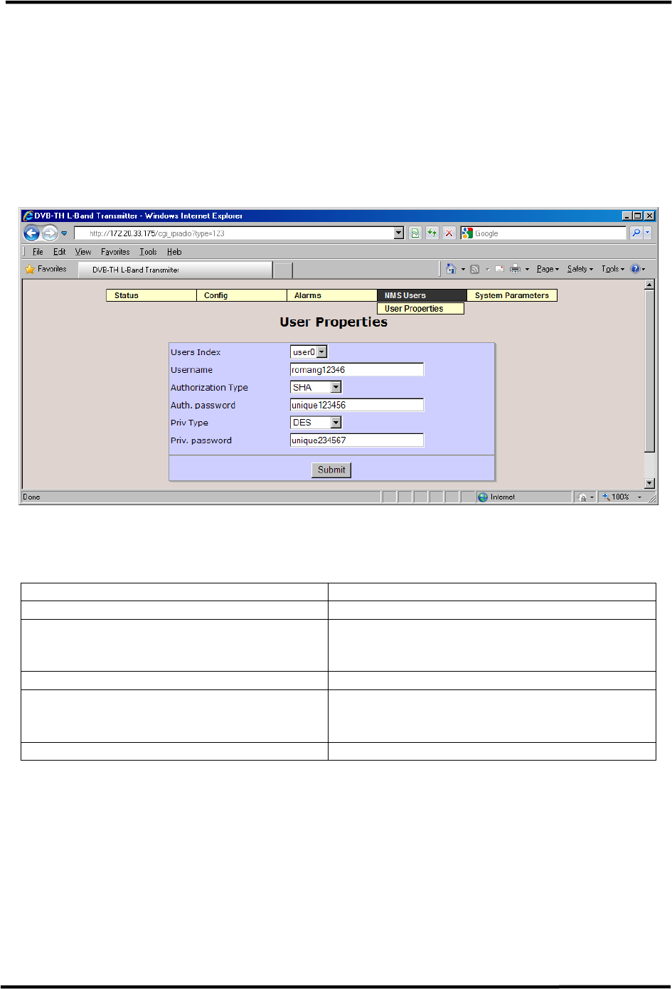
6.6 NMS Users Menu
The NMS Users menu includes the User Properties menu (see the pull down figure below).
The NMS Users menu sets the parameters required for an individual user to establish
communications with the modulator via a SNMP Network Management System (NMS). From
the User Properties menu, each NMS user can be configured with a user name, password,
Cryptographic Hash Function authentication type (SHA, MD5, none) and Data Encryption
mode (DES, AES, none) plus encryption password.
Figure 6-31 User Properties Configuration
For each user, the following authorization parameters can be set.
Item Option
Username up to 35 alphanumeric characters
Authorization Type SHA, Disabled, MD5
“Cryptographic Hash Function”
Auth. Password up to 35 alphanumeric characters
Priv Type DES, AES, Disabled
“Data Encryption”
Priv. Password up to 35 alphanumeric characters
Table 6-15 User Properties Parameters
CL1TC-4 400W DVB-H Transmitter WEB Interface
Product Manual, Rev. 1 80
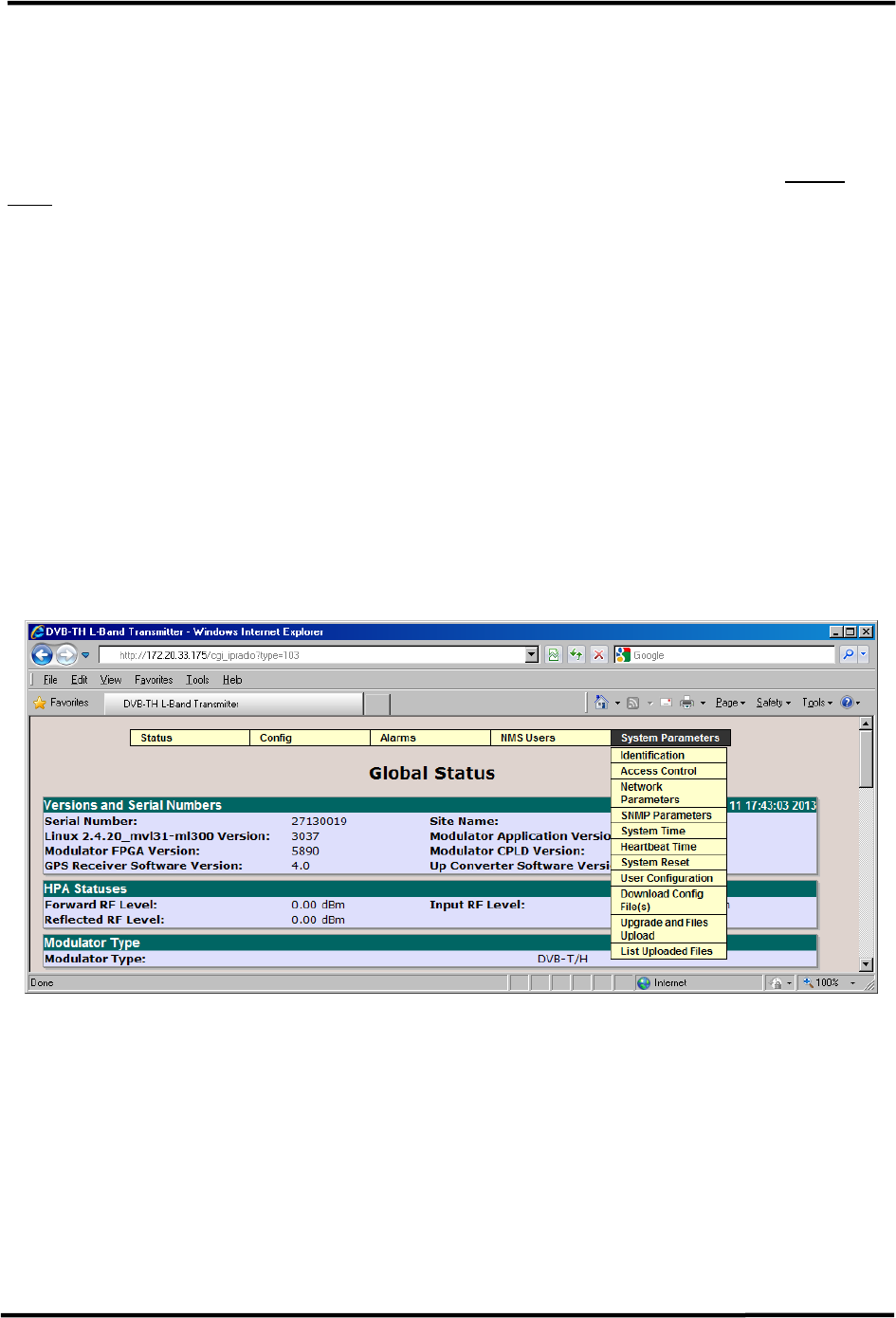
6.7 System Parameters Menu
The System Parameters menu displays the modulator access control, network and SNMP
parameters. It is also used for system reset and upgrades.
The System Parameters menu contains the following pull-down menu items (see Figure
6-32 below):
• Identification
• Access Control
• Network Parameters
• SNMP Parameters
• System Time
• Heartbeat Time
• System Reset
• User Configuration
• Download Config Files(s)
• Upgrade and Files Upload
• List Uploaded Files
Figure 6-32 System Parameters Menu
CL1TC-4 400W DVB-H Transmitter WEB Interface
Product Manual, Rev. 1 81
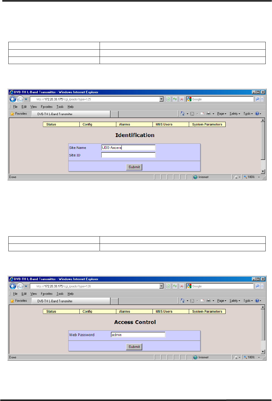
6.7.1 Identification
The Identification page allows the user to set the following identifiers:
Item Option
Site Name up to 35 alphanumeric characters
Site ID up to 15 alphanumeric characters
Table 6-16 Identification Parameters
Figure 6-33 Identification Configuration
6.7.2 Access Control
The Access Control page allows the user to set a password for the Web GUI interface.
Item Option
Web Password up to 14 alphanumeric characters
Table 6-17 Access Control Parameters
Figure 6-34 Access Control Configuration
CL1TC-4 400W DVB-H Transmitter WEB Interface
Product Manual, Rev. 1 82
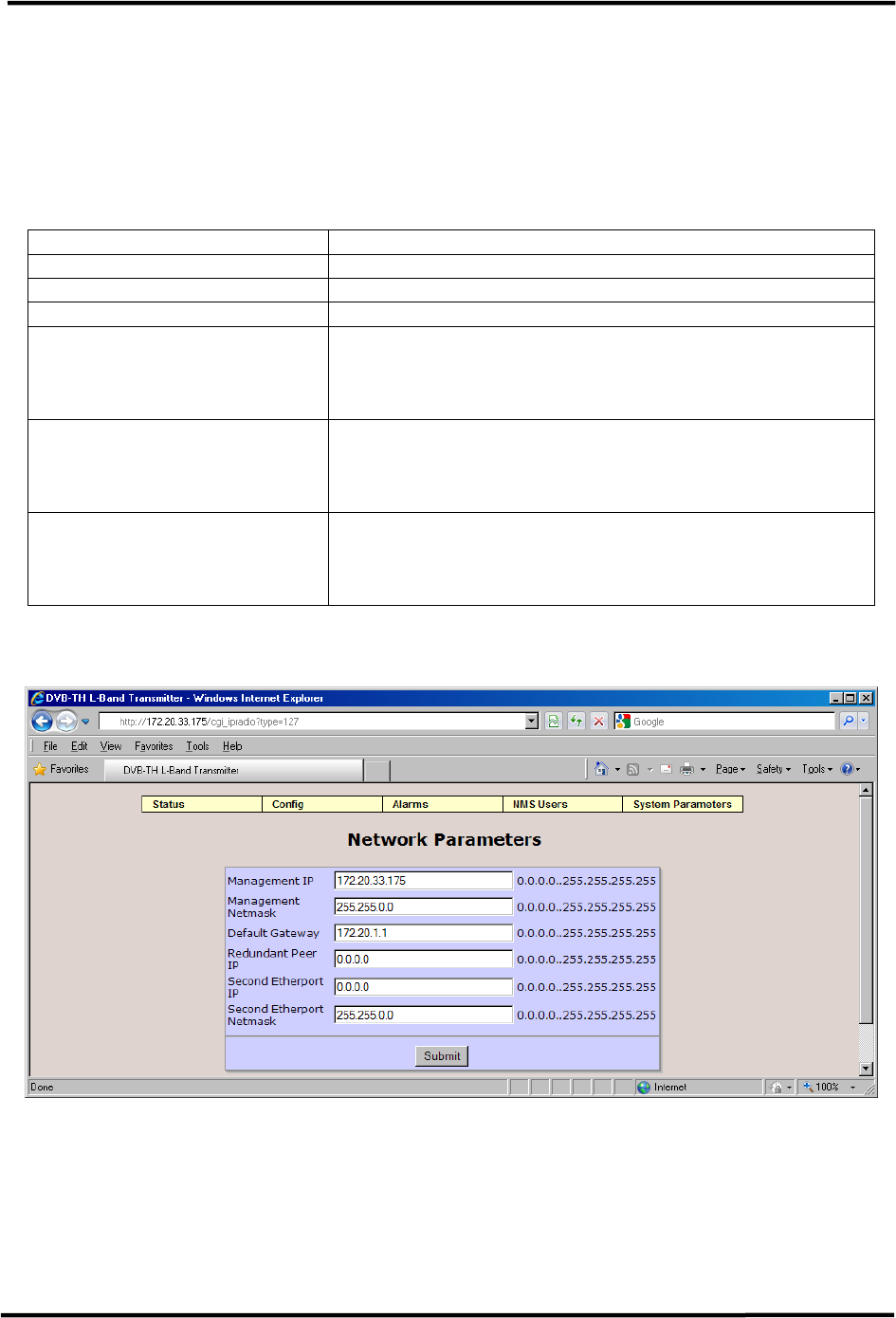
6.7.3 Network Parameters
The Network Parameters page allows the user to set the network parameters for the
modulator.
Note: The modulator must be reset following a change to any of the Network
Parameters.
Item Option
Management IP Standard IP address e.g., 172.20.25.80
Management Netmask Standard netmask field e.g., 255.255.0.0
Default Gateway Standard IP address e.g., 172.20.1.1
Redundant Peer IP Standard IP address e.g., 172.21.25.80
Not used for this application and should not be
modified by the user.
Second Etherport IP Standard IP address e.g., 172.20.25.81
Not used for this application and should not be
modified by the user.
Second Etherport Netmask Standard netmask field e.g., 255.255.0.0
Not used for this application and should not be
modified by the user.
Table 6-18 Network Parameters
Figure 6-35 Network Parameters
CL1TC-4 400W DVB-H Transmitter WEB Interface
Product Manual, Rev. 1 83
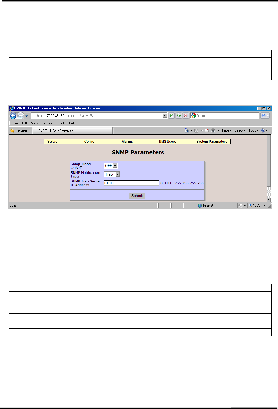
6.7.4 SNMP Parameters
The SNMP Parameters page allows the user to configure the SNMP interface for the
modulator.
Item Option
SNMP Traps On/Off OFF, ON
SNMP Notification Type Trap, Inform
SNMP Trap Server IP Address Standard IP address, e.g., 172.20.1.145
Table 6-19 SNMP Parameters
Figure 6-36 SNMP Parameters
6.7.5 System Time
The System Time page allows the user to set the system time.
Note: The modulator must be reset following a change to any of the System Time
parameters.
Item Option
Year Range: 1900 .. 3000
Month Range: 1 .. 12
Day Range: 1 .. 31
Hour Range: 0 .. 23
Minute Range: 0 .. 59
Second Range: 0 .. 59
Table 6-20 System Time Parameters
CL1TC-4 400W DVB-H Transmitter WEB Interface
Product Manual, Rev. 1 84
Figure 6-37 System Time
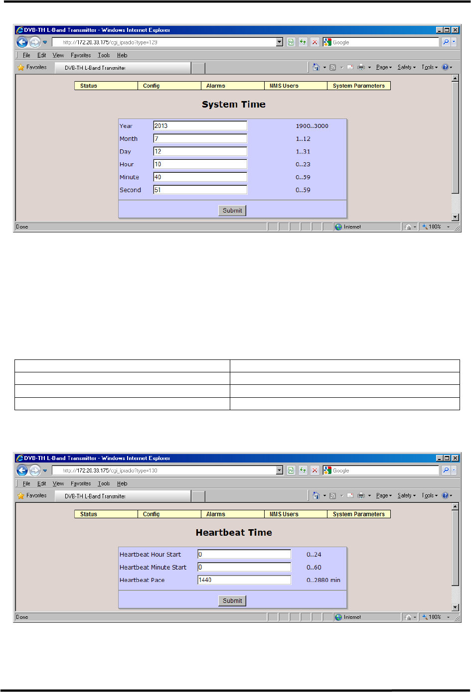
6.7.6 Heartbeat Time
The modulator has the capability to periodically send “Heartbeat” alarms and traps in order
to show that it is still operating and that communication is still active. The user can set the
Heartbeat Hours Start, Heartbeat Minute Start and repetition frequency for the heartbeat
(Heartbeat Pace).
Item Option
Heartbeat Hour Start Range: 0 .. 24
Heartbeat Minute Start Range: 0 .. 60
Heartbeat Pace 0 to 2880 min
Table 6-21 Heartbeat Parameters
Figure 6-38 Heartbeat Time
CL1TC-4 400W DVB-H Transmitter WEB Interface
Product Manual, Rev. 1 85
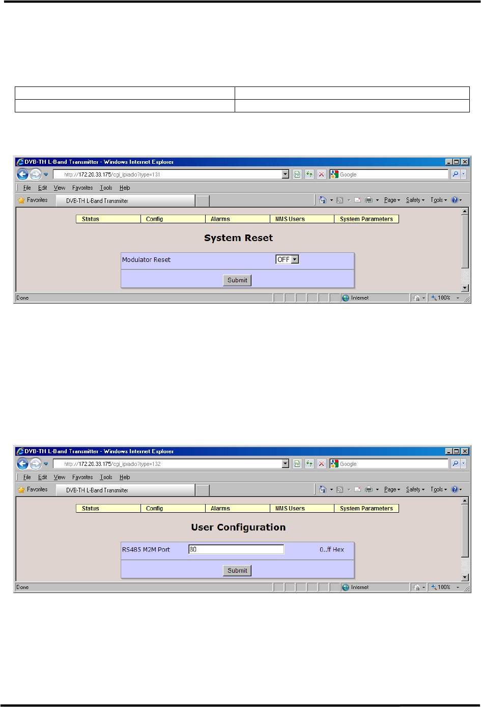
6.7.7 System Reset
The modulator can be reset by setting the Modulator Reset pull down box to ”On” and
selecting Submit.
Item Option
Modulator Reset OFF, ON
Table 6-22 System Reset Parameters
Figure 6-39 System Reset
6.7.8 User Configuration
The User Configuration page allows the user to specify the address of the serial port used
for machine-to-machine communication.
Note: User Configuration is for factory configuration only and should not be
modified by the user.
Figure 6-40 User Configuration
CL1TC-4 400W DVB-H Transmitter WEB Interface
Product Manual, Rev. 1 86
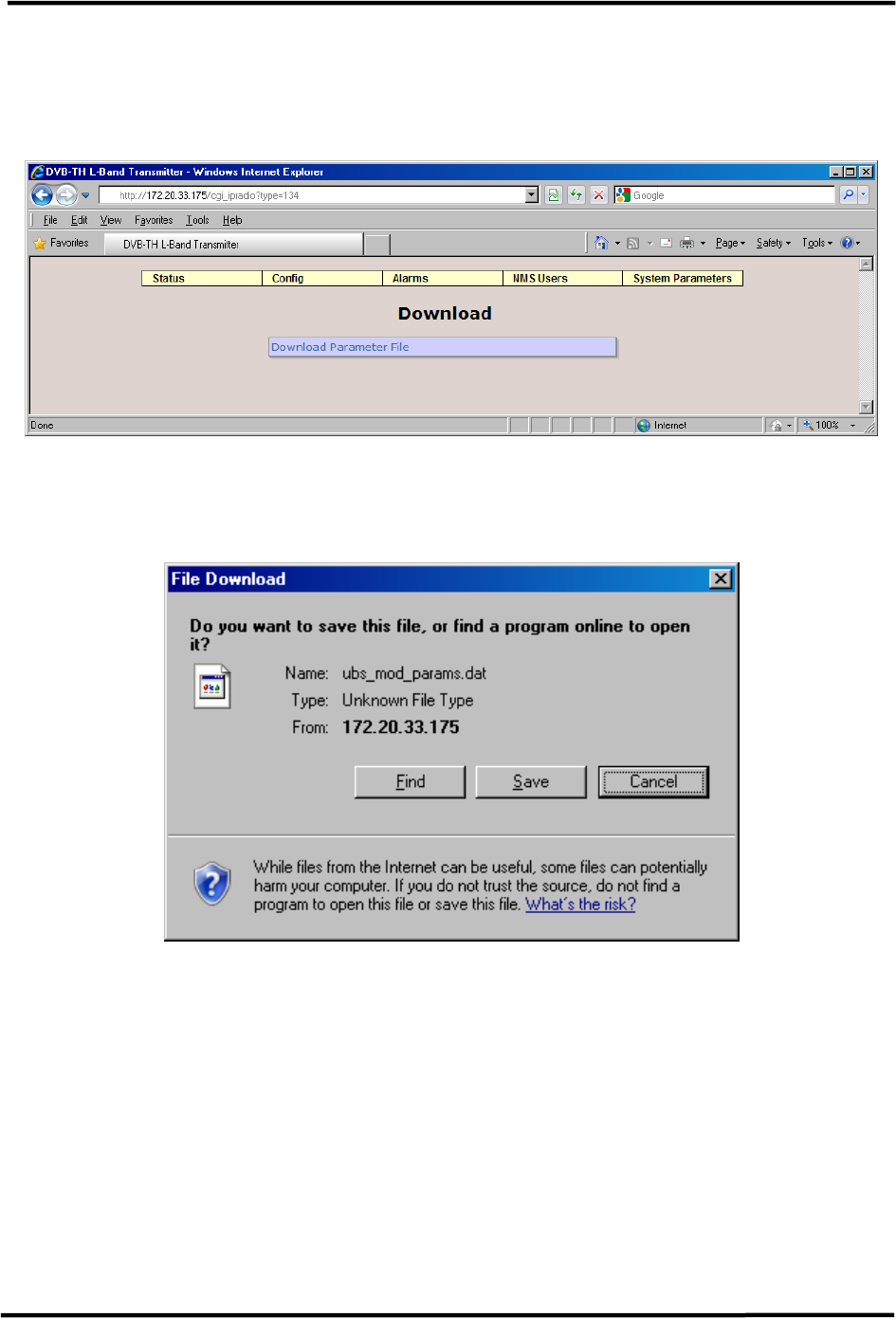
6.7.9 Download Config Files(s)
The Download Config File(s) page allows the user to download files located on the
modulator.
Figure 6-41 Download Config Files(s)
By clicking on the Download Parameter File box the user will see an operating system pop-
up window, prompting the user to save the configuration file on their system:
Figure 6-42 Download Pop-Up Window (Windows OS)
CL1TC-4 400W DVB-H Transmitter WEB Interface
Product Manual, Rev. 1 87
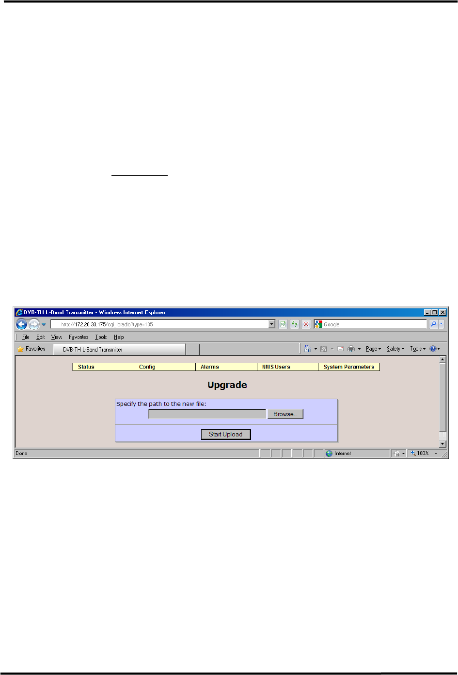
6.7.10 Upgrade and Files Upload Procedure
The Upgrade and Files Upload page allows the user to upgrade system software components
such as:
• Modulator Application
• Linux Kernel (included in the Modulator Application)
• Modulator FPGA
• Up-converter Software
The first step in the upgrade process is the selection of the proper upgrade file using the
“Browse” button (see Figure 6-43). Once the file is selected, click on “Start Download” to
initiate the upgrade process.
Please note that the Web server is a single threaded server which only allows one
connection at a time. Therefore if the upgrade is performed via a phone line, the file
transfer can take 10 minutes depending on the connection speed and file size. The contents
of the pop-up dialog will be blank. It will only start showing the upgrade information when
the file is completely transferred.
The upgrade file contains all the information required to define the component which is
being upgraded.
Figure 6-43 Upgrade and Files Upload
CL1TC-4 400W DVB-H Transmitter WEB Interface
Product Manual, Rev. 1 88
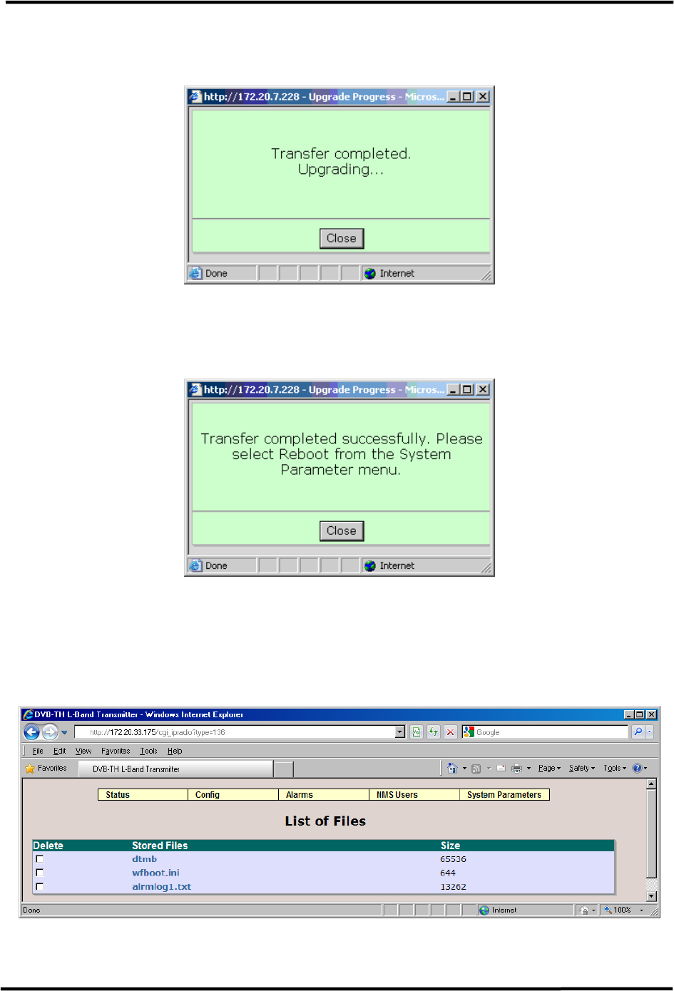
As the upgrade starts a pop-up dialog will appear with the current upgrade process
information.
Figure 6-44 Upgrade Begin Pop-Up
Once the upgrade is complete the pop up dialog will display a corresponding message.
Figure 6-45 Upgrade Complete Pop-Up
6.7.11 List Uploaded Files
The List Uploaded Files page provides a list of uploaded files on the modulator.
Figure 6-46 List Uploaded Files
CL1TC-4 400W DVB-H Transmitter CLI
Product Manual, Rev. 1 89
7 Command Line Interface (CLI)
7.1 Introduction
The transmitter can be controlled and monitored from the Command Line Interface (CLI) in
addition to the Web GUI and front panel.
The CLI is accessible from the USB port or via a Telnet session through the Ethernet
management port.
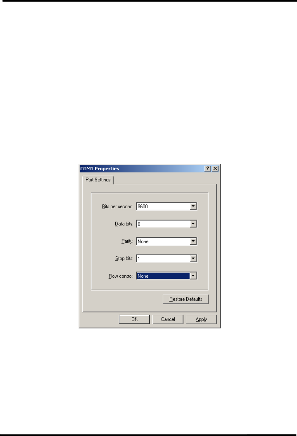
7.2 Using the USB Port to access the CLI
The modulator must be connected to a PC using a USB-to-USB cable. The cable will require
a USB Type B connector to mate with the modulator USB port, while the other connector
has to mate with the PC USB port.
Open a Hyperterminal (or HyperACCESS depending on the operating system) session on the
PC and set the parameters as shown below:
Figure 7-1 COM settings
CL1TC-4 400W DVB-H Transmitter CLI
Product Manual, Rev. 1 90
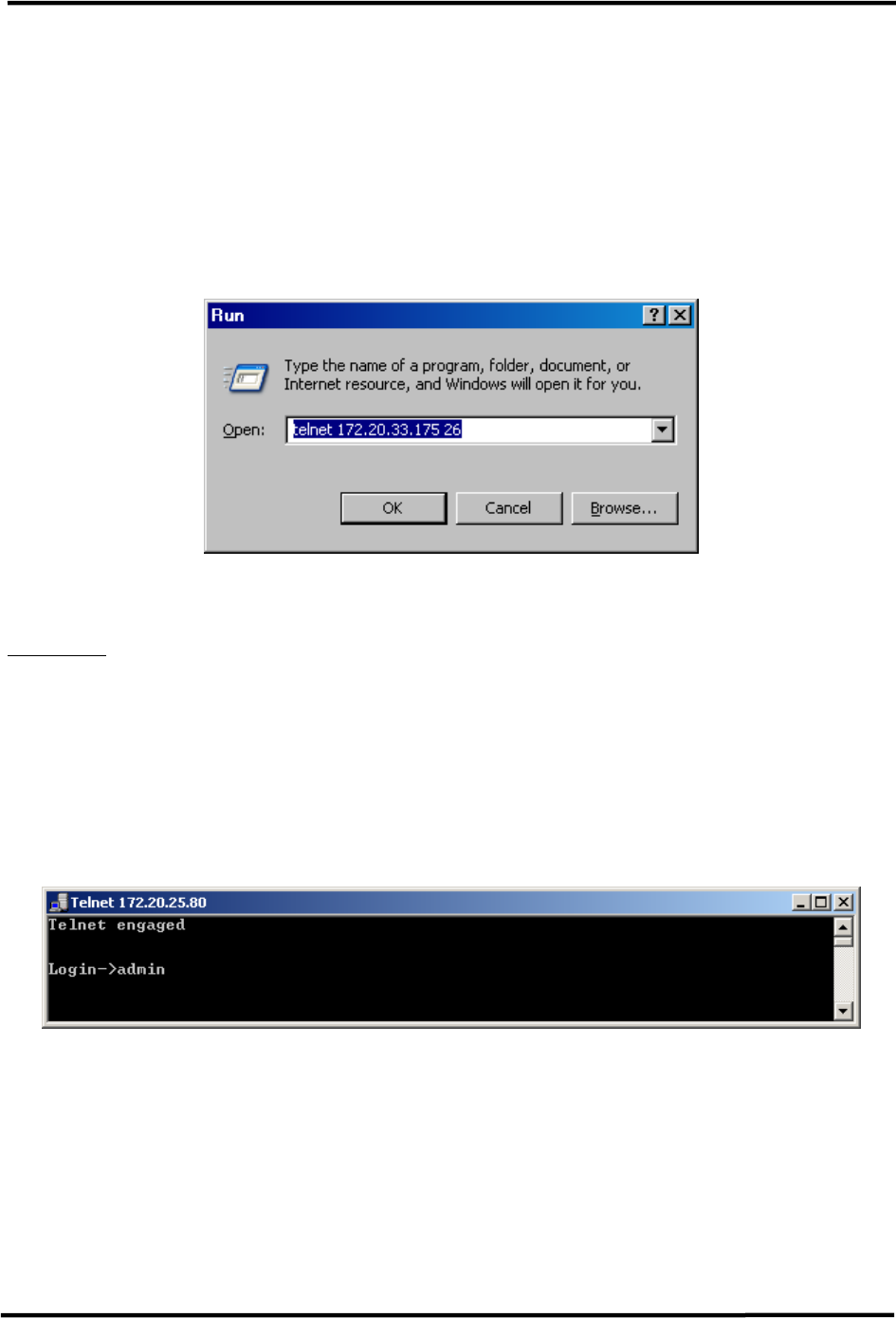
7.3 Using Ethernet Port to access the CLI
The modulator can be connected directly to a PC or through a hub/switch using an RJ-45
straight-through cable.
The modulator and PC must be configured to be on the same IP network so that a
connection can be established.
A Telnet client can be opened from the “Start/Run” button on the PC. Enter the IP address
assigned to the modulator followed by the number 26 – see below.
Figure 7-2 Starting the Telnet session
A HyperTerminal session can also be used to access the CLI through the Ethernet port – see
Figure 7-1.
7.4 CLI Login Procedure
1. Once the connection has been established, press enter to get to the login prompt.
2. Enter the password and press enter. NOTE: The password is “admin” by default, but
can be changed through the Web GUI, CLI or SNMP.
3. After the password has been verified, the main menu will appear.
Figure 7-3 Telnet Login Prompt

CL1TC-4 400W DVB-H Transmitter CLI
Product Manual, Rev. 1 91
7.5 CLI Menu System
The CLI contains a three level menu system where parameters can be viewed and changed.
7.5.1 Navigation
Each menu has been assigned a numeric value for navigation purposes. To navigate
through the CLI menu system, enter the number assigned to the desired menu. Depending
on the menu accessed, the user may have the option to enter a sub-menu, or change a
system parameter.
The following menu prompts are available for navigation and for changing system
parameters:
• Enter Selection – allows the user to change menus or exit the CLI
• Enter New Value – allows the user to change a system parameter
At the “Enter Selection” prompt, the user may also use the following keys to navigate or
exit the CLI menu system:
• r – return to the previous menu
• e – exit the CLI
If the user accesses the “Enter New Value” prompt by mistake or decides that they do not
want to change a parameter, the prompt can be exited without making a parameter change.
Simply clear all alphanumeric parameters and press enter. See the following example
below:
Identification
1. Site Name
2. Site ID
r. Return to previous menu
e. Exit CLI
Enter selection : 2 Site ID
Current Value:
Enter New value: No Changes
7.5.2 Parameter Values
In some cases, such as entering the Guard Interval or Code Rate, the selectable parameters
have been assigned a numeric value. This allows the user to change the parameter by
simply entering the number assigned to a different parameter. In other cases, such as
entering the transmitter IP address or Site Information, the user can enter a range of
alphanumeric characters.
All parameter changes are made at the “Enter New Value” prompt.
Enter selection : 6 RF Output Frequency
Current Value: 1670000000 Hz
Range: 1670000000 .. 1675000000
Enter New value:

CL1TC-4 400W DVB-H Transmitter CLI
Product Manual, Rev. 1 92
7.5.3 Menu Tree
The CLI Menu tree is listed below with a total of 3 levels.
Main Menu:
1. Status
2. Config
3. Alarms
4. NMS Users
5. System Parameters
6. Display Alarms
7. Firmware Upgrade
r. Return to previous menu
e. Exit CLI
Enter selection:
Main Menu Level 2 Level 3
1. Status 1. Global Status
2. GPS Status
3. HPA
2. Config 1. Modulator Mode
2. Config 2. Transmission
1. SFN
2. Config From Stream
3. Fixed Delay
4. Input_Output Fixed Delay
5. MIP Time Offset Function
6. MIP Frequency Offset Function
7. MIP Power Function
8. MIP CellId Function
9. Hierarchical Mode
10. IFFT
11. Coderate
12. Constellation
13. Guard Interval
14. Interleaver Flag
15. Time Slice Indicator
16. MPE-FEC Flag, HP
17. Cell Id
18. Transmitter ID
19. Local DelayOffset
2. Config 3. Input 1. Selected Input
2. IP Input Interface
3. Input Stream Dst IP
4. Input Stream Dst Port
5. FEC Mode
6. IP Input Buffer Depth
2. Config 4. Output 1. Mute ON/OFF
2. Bandwidth
3. Spectrum Inversion
4. Window Enable
5. External Amplifier Gain
6. RF Output Frequency
7. RF Power Level
8. RF Channel Grid

CL1TC-4 400W DVB-H Transmitter CLI
Product Manual, Rev. 1 93
Main Menu Level 2 Level 3
2. Config 4. Output 9. Base Frequency
10. Base Channel
2. Config 5. RF Channels Select RF Channel
2. Config 6. User RF Channels Select RF Channel
2. Config 7. Non-Linear Precorrector 1. NLP State
2. NLP Profile
2. Config 8. Linear Precorrector 1. LP State
2. LP Profile
2. Config 9. HPA Control 1. RF Output Power Level
2. Transmitter Operating Mode
2. Config 10. GPS 1. Max GPS Holdover Time, min
2. Update System Clock From GPS
3. System Timezone
2. Config 11. Site 1. System Description
2. Contact Information
3. System Location
4. Site Address Line 1
5. Site Address Line 2
6. Site Address Line 3
7. Site Address Line 4
8. Site Notes
3. Alarms 1. Alarm Properties 1. Alarm Index
2. Alarm Enabled
3. Trap Notification on Alarm
4. Integration Time
5. Mute on Alarm
6. Relay on Alarm
7. Second Relay on Alarm
8. Alarm Severity Level
3. Alarms 2. External Voltage Alarm
Setting
1. Voltage1 Trigger Polarity
2. Voltage1 Trigger Threshold
3. Voltage2 Trigger Polarity
4. Voltage2 Trigger Threshold
5. Voltage3 Trigger Polarity
6. Voltage3 Trigger Threshold
7. Voltage4 Trigger Polarity
8. Voltage4 Trigger Threshold
9. Voltage5 Trigger Polarity
10. Voltage5 Trigger Threshold
11. Voltage6 Trigger Polarity
12. Voltage6 Trigger Threshold
13. Voltage7 Trigger Polarity
14. Voltage7 Trigger Threshold
15. Voltage8 Trigger Polarity
16. Voltage8 Trigger Threshold
3. Alarms 3. Log Management 1. Clear Alarm Log
2. Logs Display In Reverse
3. Log To Display

CL1TC-4 400W DVB-H Transmitter CLI
Product Manual, Rev. 1 94
Main Menu Level 2 Level 3
4. NMS Users 1. User Properties 1. User Index
2. Username
3. Authorization Type
4. Auth. Password
5. Priv Type
6. Priv. Password
5. System
Parameters
1. Identification 1. Site Name
2. Site ID
5. System
Parameters
2. Access Control Enter Web Password
5. System
Parameters
3. Network Parameters 1. Management IP
2. Management Netmask
3. Default Gateway
4. Redundant Peer IP
5. Second Etherport IP
6. Second Etherport Netmask
5. System
Parameters
4. SNMP Parameters 1. SNMP Traps On/Off
2. SNMP Notification Type
3. SNMP Trap Server IP Address
5. System
Parameters
5. System Time 1. Year
2. Month
3. Day
4. Hour
5. Minute
6. Second
5. System
Parameters
6. Heartbeat Time 1. Heartbeat Hour Start
2. Heartbeat Minute Start
3. Heartbeat Pace
5. System
Parameters
7. System Reset Modulator Reset
5. System
Parameters
8. User Configuration Set RS485 port address
6. Display
Alarms
7. Firmware
Upgrade
Enter URL
Table 7-1 CLI Menu Tree

CL1TC-4 400W DVB-H Transmitter CLI
Product Manual, Rev. 1 95
7.5.3.1 Status Sub-menu
Status:
1. Global Status
2. GPS Status
3. HPA
r. Return to previous menu
e. Exit CLI
Enter selection :
Status Sub-menu Description
1. Global Status Displays general status information for network
management, alarms, modulation, transmitter output
and reflected power values as well as transmitter
frequency.
2. GPS Status Displays detailed GPS information such as site co-
ordinates, altitude, GPS PLL and 3D fix status and
satellite tracking.
3. HPA Displays detailed HPA status information such as forward,
reflected and input power levels, current values for the
pre-driver, driver and PA modules, heat sink
temperature, as well as power supply voltage.
Table 7-2 Status Sub-menu
7.5.3.2 Config Sub-menu
Config:
1. Modulator Mode
2. Transmission
3. Input
4. Output
5. RF Channels
6. User RF Channels
7. Non-Linear Precorrecto
8. Linear Precorrector
9. HPA Control
10. GPS
11. Site
r. Return to previous menu
e. Exit CLI
Enter selection :

CL1TC-4 400W DVB-H Transmitter CLI
Product Manual, Rev. 1 96
Config
Sub-menu
Sub-menu Selectable Parameters
1. Modulator Mode 0. Normal
1. CW
2. Test 1(Carriers Removed)
3. Record
4. Playback
2. Transmission 1. SFN 0. OFF
1. ON
2. Transmission 2. Config From Stream 0. ON
1. OFF
2. Transmission 3. Fixed Delay 0. OFF
1. ON
2. Transmission 4. Input_Output Fixed Delay Range: 13000 .. 1000000 µsec
2. Transmission 5. MIP Time Offset Function 0. OFF
1. ON
2. Transmission 6. MIP Frequency Offset
Function
0. OFF
1. ON
2. Transmission 7. MIP Power Function 0. OFF
1. ON
2. Transmission 8. MIP Cell Id Function 0. OFF
1. ON
2. Transmission 9. Hierarchical Mode 0. None
1. 1
2. 2
3. 4
2. Transmission 10. IFFT 0. 2k
1. 8k
2. 4k
2. Transmission 11. Coderate 0. 1/2
1. 2/3
2. 3/4
3. 5/6
4. 7/8
2. Transmission 12. Constellation 0. QPSK
1. 16 QAM
2. 64 QAM
2. Transmission 13. Guard Interval 0. 1/32
1. 1/16
2. 1/8
3. 1/4
2. Transmission 14. Interleaver Flag 0. OFF
1. ON
2. Transmission 15. Time Slice Indicator, HP 0. OFF
1. ON
2. Transmission 16. MPE-FEC Flag, HP 0. OFF
1. ON
2. Transmission 17. Cell ID Range: 0 .. 65535

CL1TC-4 400W DVB-H Transmitter CLI
Product Manual, Rev. 1 97
Config
Sub-menu
Sub-menu Selectable Parameters
2. Transmission 18. Transmitter ID Range: 0 .. 100
2. Transmission 19. Local Delay Offset Range: -500000 .. 500000
3. Input 1. Selected Input 0. A
1. B
2. Auto
3. IP
3. Input 2. IP Input Interface 0. Ethernet 2
1. Ethernet 1
3. Input 3. Input Stream Dst IP Range: 0.0.0.0 ..
255.255.255.255
3. Input 4. Input Stream Dst Port Range: 1025 .. 65535
3. Input 5. FEC Mode 0. None
1. Column Only
2. Column+Row
3. Input 6. IP Input Buffer Depth Range: 0 .. 500 Packets
4. Output 1. Mute ON/OFF 0. OFF
1. ON
4. Output 2. Bandwidth 0. 5 MHz
4. Output 3. Spectrum Inversion 0. OFF
1. ON
4. Output 4. Window Enable 0. OFF
1. ON
4. Output 5. External Amplifier Gain Range: 0 .. 6553.5 dB
4. Output 6. RF Output Frequency Range: 1670000000 ..
1675000000 Hz
4. Output 7. RF Power Level Range: -10.0 .. 0.0 dBm
4. Output 8. RF Channel Grid 0. DVBT UHF 8M 474-858 MHz
1. User Defined
4. Output 9. Base Frequency Range: 1670000000 ..
1675000000 Hz
4. Output 10. Base Channel Range: 1 .. 200
5. RF Channels 1. CH 21 (474 MHz) to
49. CH 69 (858 MHz)
6. User RF
Channels
User Defined
7. Non-Linear
Pre-corrector
1. NLP State 0. OFF
1. ON
7. Non-Linear
Pre-corrector
2. NLP Profile 0 .. 9
8. Linear
Pre-corrector
1. LP State 0. OFF
1. ON

CL1TC-4 400W DVB-H Transmitter CLI
Product Manual, Rev. 1 98
Config
Sub-menu
Sub-menu Selectable Parameters
8. Linear
Pre-corrector
2. LP Profile 0 .. 9
9. HPA Control 1. RF Output Power Level Range: 46.00 .. 56.00 dBm
9. HPA Control 2. Transmitter Operating
Mode
0. Standby
1. Broadcast
2. Manual
10. GPS 1. Max GPS Holdover Time,
min
Range: 0 .. 65535
10. GPS 2. Update System Clock from
GPS
0. No
1. Yes
10. GPS 3. System Timezone 0. n11 12. 1
1. n10 13. 2
2. n9 14. 3
3. n8 15. 4
4. n7 16. 5
5. n6 17. 6
6. n5 18. 7
7. n4 19. 8
8. n3 20. 9
9. n2 21.10
10. n1 22.11
11. 0
11. Site 1. System Description up to 35 characters
11. Site 2. Contact Information up to 35 characters
11. Site 3. System Location up to 35 characters
11. Site 4. Site Address Line 1 up to 35 characters
11. Site 5. Site Address Line 2 up to 35 characters
11. Site 6. Site Address Line 3 up to 35 characters
11. Site 7. Site Address Line 4 up to 35 characters
11. Site 8. Site Notes up to 35 characters
Table 7-3 Config Sub-menu

CL1TC-4 400W DVB-H Transmitter CLI
Product Manual, Rev. 1 99
7.5.3.3 Alarms Sub-menu
Alarms:
1. Alarm Properties
2. External Voltage Alarm Setting
3. Log Management
r. Return to previous menu
e. Exit CLI
Enter selection :
Alarms Sub-menu Sub-menu Selectable Parameters
1. Alarm Properties 1. Alarm Index See Table 10-1
1. Alarm Properties 2. Alarm Enabled 0. OFF
1. ON
1. Alarm Properties 3. Trap Notification on
Alarm
0. OFF
1. ON
1. Alarm Properties 4. Integration Time Range: 0 .. 360
1. Alarm Properties 5. Mute Output on Alarm 0. OFF
1. ON
1. Alarm Properties 6. Relay on Alarm 0. OFF
1. ON
1. Alarm Properties 7. Second Relay on Alarm 0. OFF
1. ON
1. Alarm Properties 8. Alarm Severity Level 0. Critical
1. Warning
2. Informative
3. Cleared
2. External Voltage
Alarm Setting
1. Voltage1 Trigger Polarity 0. <
1. >
2. External Voltage
Alarm Setting
2. Voltage1 Trigger Threshold Range: 0 .. 10
2. External Voltage
Alarm Setting
3. Voltage2 Trigger Polarity 0. <
1. >
2. External Voltage
Alarm Setting
4. Voltage2 Trigger Threshold Range: 0 .. 10
2. External Voltage
Alarm Setting
5. Voltage3 Trigger Polarity 0. <
1. >
2. External Voltage
Alarm Setting
6. Voltage3 Trigger Threshold Range: 0 .. 10
2. External Voltage
Alarm Setting
7. Voltage4 Trigger Polarity 0. <
1. >
2. External Voltage
Alarm Setting
8. Voltage4 Trigger Threshold Range: 0 .. 10
2. External Voltage
Alarm Setting
9. Voltage5 Trigger Polarity 0. <
1. >
2. External Voltage
Alarm Setting
10. Voltage5 Trigger Threshold Range: 0 .. 10
2. External Voltage
Alarm Setting
11. Voltage6 Trigger Polarity 0. <
1. >

CL1TC-4 400W DVB-H Transmitter CLI
Product Manual, Rev. 1 100
2. External Voltage
Alarm Setting
12. Voltage6 Trigger Threshold Range: 0 .. 10
2. External Voltage
Alarm Setting
13. Voltage7 Trigger Polarity 0. <
1. >
2. External Voltage
Alarm Setting
14. Voltage7 Trigger Threshold Range: 0 .. 10
2. External Voltage
Alarm Setting
15. Voltage8 Trigger Polarity 0. <
1. >
2. External Voltage
Alarm Setting
16. Voltage8 Trigger Threshold Range: 0 .. 10
3. Log Management 1. Clear Alarm Log 0. No
1. Yes
3. Log Management 2. Logs Display in Reverse 0. No
1. Yes
3. Log Management 3. Log to Display 0. Transient Log
1. Alarm Log
Table 7-4 Alarms Sub-menu
7.5.3.4 NMS Users Sub-menu
NMS Users:
1. User Properties
r. Return to previous menu
e. Exit CLI
Enter selection :
NMS Users Sub-
menu
Sub-menu Selectable Parameters
1. User Properties 1. User Index
1. User Properties 2.Username up to 35 characters
1. User Properties 3. Authorization Type 0. Disabled
1. MD5
2. SHA
1. User Properties 4. Auth. Password up to 35 characters
1. User Properties 5. Priv Type 0. Disabled
1. DES
2. AES
1. User Properties 6. Priv. Password up to 35 characters
Table 7-5 NMS Users Sub-menu

CL1TC-4 400W DVB-H Transmitter CLI
Product Manual, Rev. 1 101
7.5.3.5 System Parameters Sub-menu
System Parameters:
1. Identification
2. Access Control
3. Network Parameters
4. SNMP Parameters
5. System Time
6. Heartbeat Time
7. System reset
r. Return to previous menu
e. Exit CLI
Enter selection:
System Parameters
Sub-menu
Sub-menu Selectable Parameters
1. Identification 1. Site Name up to 35 characters
1. Identification 2. Site ID up to 15 characters
2. Access Control Web Password up to 14 characters
3. Network Parameters 1. Management IP Range: 0.0.0.0 ..
255.255.255.255
3. Network Parameters 2. Management Netmask Range: 0.0.0.0 ..
255.255.255.255
3. Network Parameters 3. Default Gateway Range: 0.0.0.0 ..
255.255.255.255
3. Network Parameters 4. Redundant Peer IP Range: 0.0.0.0 ..
255.255.255.255
3. Network Parameters 5. Second Etherport IP Range: 0.0.0.0 ..
255.255.255.255
3. Network Parameters 6. Second Etherport
Netmask
Range: 0.0.0.0 ..
255.255.255.255
4. SNMP Parameters 1. SNMP Traps On/Off 0. OFF
1. ON
4. SNMP Parameters 2. SNMP Trap Server IP
Address
Range: 0.0.0.0 ..
255.255.255.255
5. System Time 1. Year Range: 1900 .. 3000
5. System Time 2. Month Range: 1 .. 12
5. System Time 3. Day Range: 1 .. 31
5. System Time 4. Hour Range: 0 .. 23
5. System Time 5. Minute Range: 0 .. 59
5. System Time 6. Second Range: 0 .. 59
6. Heartbeat Time 1. Heartbeat Hour Start Range: 0 .. 24
6. Heartbeat Time 2. Heartbeat Minute Start Range: 0 .. 60
6. Heartbeat Time 3. Heartbeat Pace Range: 0 .. 99999999
7. System Reset Modulator Reset 0. OFF
1. ON
Table 7-6 System Parameters Sub-menu

CL1TC-4 400W DVB-H Transmitter CLI
Product Manual, Rev. 1 102
7.5.3.6 Display Alarms Sub-menu
This Sub-menu simply displays any active alarms. See below as an example:
Enter Selection : 6Alarms:
No Input Data
HPA Controller Comm Err
7.5.3.7 Firmware Upgrade
This Sub-menu allows the user to enter a URL address from which the transmitter can
obtain a firmware upgrade.
Enter URL:
CL1TC-4 400W DVB-H Transmitter Modulator Front Panel
Product Manual, Rev. 1 103
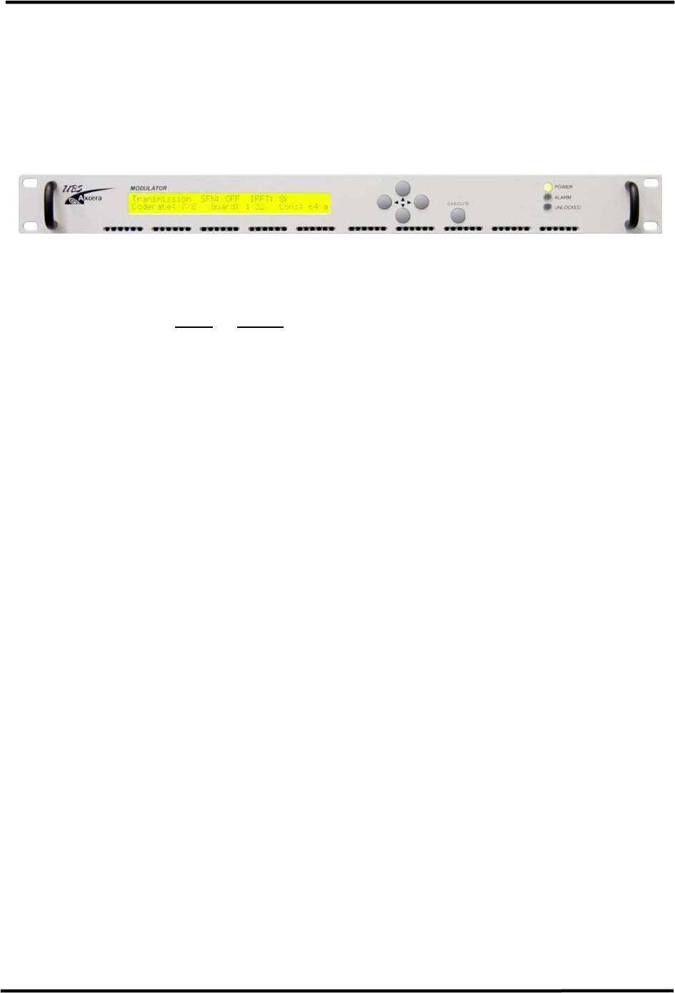
8 Modulator Front Panel Interface
8.1 Introduction
The front panel system includes both Status Displays where important parameters are
prominently displayed and the four-level Config Menu system where system parameters can
be entered. A picture of the modulator front panel is shown below.
Figure 8-1 Modulator Front Panel
The modulator front panel offers all the same access as the Web GUI (normal access level
only) with the obvious exception of files download, file listing and system upgrade utilities of
the Web GUI (Sections 6.7.9 to 6.7.11). Refer to the Web-GUI section of the manual for a
more detailed description of all parameters.
8.2 Controls
8.2.1 Navigation
Navigation between menu items makes use of the five buttons on the front panel display.
e (left)
f (right)
c (up)
d (down)
EXECUTE
The c button is used to scroll through the different status display windows, exit the current
menu and enter a higher-level menu, increase alpha-numerical parameters or abort
confirmation of a change
The d button is used to scroll through the different status display windows, exit the current
menu and enter a sub-menu, decrease alpha-numerical parameters or abort confirmation of
a change
The e and f buttons are used to scroll horizontally through the Config menus, the
parameter listings and the parameter characters, in the case of editable parameters. They
are also used to increase and decrease % parameters.
The EXECUTE button is used to enter the configuration menu system (GENERIC or
SPECIFIC) from a status display window, to enter a sub-menu and confirm changes made to
configurable parameters.
Examples A and B display the menu system top level. The character string “DVB-TH L-Band
TX” is always positioned in the top left corner of the display. The available menu items are
shown on the second line and may be selected using the 3 and 8 buttons.

CL1TC-4 400W DVB-H Transmitter Modulator Front Panel
Product Manual, Rev. 1 104
The “current” menu item is always shown in capitalized format with “< >” brackets. If there
are more menu items than the LCD can display, three (3) dots are shown in the lower right
position – see Example A.
Example A
----------------------------------------
DVB-TH L-Band TX
<CONFIG> Alarms NMS Users System Pa...
----------------------------------------
If the user presses the 8 button, the display will shift to the left and the next menu item
will be selected – see Example B.
Example B
----------------------------------------
DVB-TH L-Band TX
<ALARMS> NMS Users System Parameters...
----------------------------------------
If the user presses the 6 button in Example A, the highlighted menu item will be selected
and the user will enter the sub-menu – see Example C.
The character string “DVB-TH L-Band TX” is always positioned in the top left corner of the
display, followed by the menu name. The available menu items are shown on the second
line and may be selected using the 3 and 8 buttons. The “current” menu item is always
shown in capitalized format with “< >” brackets. If there are more menu options than the
LCD can display, three (3) dots are shown in the lower right position.
Example C
----------------------------------------
DVB-TH L-Band TX, Config
<MODULATOR MODE> Transmission Input ...
----------------------------------------
The lowest level of any particular “branch” produces a window that displays the available
parameter list; the selected value is shown in square brackets – see Example D.
The parameter name is shown in the top left corner of the display, followed by the “current”
value. The available menu items are shown on the second line and may be selected using
the 3 and 8 buttons. The “current” menu item is always shown in capitalized format with
“[ ]” brackets.
Example D
----------------------------------------
Spectrum Inversion = OFF
[OFF] ON
----------------------------------------
If an alpha numeric parameter is selected, the first digit of the “current” parameter flashes
and a cursor shows the position of the digit which can be edited (in this case, “a” from
“admin”) – see Example E.

CL1TC-4 400W DVB-H Transmitter Modulator Front Panel
Product Manual, Rev. 1 105
Example E
----------------------------------------
Web Password = admin
admin
----------------------------------------
8.2.2 Configuring Parameters
8.2.2.1 Selection of Enumerated Values
----------------------------------------
Modulator Mode = Normal
[Normal] CW Test 1(Carriers Removal...
----------------------------------------
(the square brackets flash at approx. 2 Hz)
The current value is shown as the first item in the list, in square brackets.
Navigating:
w Scrolls the previous item into the “current position”.
8 Scrolls the next item into the “current position”.
6 No effect.
5 Aborts editing and returns to the previous menu level.
<EXECUTE> Saves the “current” item as the active parameter and returns to the previous
menu level.
8.2.2.2 Editing a Numeric Value
----------------------------------------
RF Output Frequency = 1670000000
1670000000 [167000000..1675000000]
----------------------------------------
(the character 0 alternates between ‘0’ and ‘_’ at approximately 2 Hz)
The configurable value that appears on the display is always the current value and the cursor is initially
positioned on the last digit. The valid range is displayed in square brackets on the right hand side of the
bottom line.
Navigating:
w Positions the cursor on the previous character or moves to the last character when
the cursor is on the first character.
8 Positions the cursor on the next character or moves to the first character when the
cursor is on the last character.
6 Decrements the value of the highlighted character. If the character value is ‘0’, the
button will change the value to ‘9’. If the parameter can be set to a negative
number, the button will toggle between a negative sign (-) and a blank (positive)
when the first character is highlighted.
5 Increments the value of the highlighted character. If the character value is ‘9’, the 5
button will change the value to ‘0’. If the parameter can be set to a negative
number, the 5 button will toggle between a negative sign (-) and a blank (positive)
when the first character is highlighted.

CL1TC-4 400W DVB-H Transmitter Modulator Front Panel
Product Manual, Rev. 1 106
EXECUTE Completes editing.
Note 1: If a configurable numeric item has a minimum and/or maximum value,
the user cannot modify the value below the minimum or above the maximum.
Note 2: Incrementing one character above ‘9’ will change this character to ‘0’ and
will increment the next character to the left by one (“carry-on digit”). Similarly,
decrementing one character below ‘0’ will change this character to ‘9’ and
decrement the next character to the left by one.
8.2.2.3 Editing a Text Value
----------------------------------------
Web Password
admin
----------------------------------------
(the character ‘a’ alternates between ‘a’ and ‘_’ at approximately 2 Hz)
The current text string is shown as the editable value. The characters A..Z, a..z, 0..9, -
(minus), _(underscore) and “ “(space) are all supported.
Navigating:
w Positions cursor on previous character.
8 Positions cursor on next character.
6 Decrements the value of the highlighted character in a circular manner.
5 Increments the value of the highlighted character in a circular manner.
EXECUTE Completes editing.
8.2.2.4 Saving Changes
To save changes to a menu item press the EXECUTE button. The following display will
appear:
----------------------------------------
Save = EXECUTE, Cancel = other keys
----------------------------------------
Press the EXECUTE button again to save the change or any other button to cancel. After a
short period of time with no input, the operation is cancelled automatically and the display
reverts to the menu directly above the menu just visited.

CL1TC-4 400W DVB-H Transmitter Modulator Front Panel
Product Manual, Rev. 1 107
8.3 Modulator Boot-up
The user will see the following displays in sequence.
----------------------------------------
Front Panel v1.22 Loading......
>>>>>>>>>>>>>>>>>>>>>>>>>>>>>>>>>>>>>>>>
----------------------------------------
----------------------------------------
DVB-TH/SH 5000 Modulator
----------------------------------------
----------------------------------------
CL1TC-4 Transmitter
----------------------------------------
When boot-up is complete the user will see the default status display which is screen b of
the Status display set:
----------------------------------------
Input HP Input: Auto Status: Locked
b
----------------------------------------
Note the flashing letter b that appears in the lower right hand corner. If there is no activity
for a period of several minutes the modulator will automatically revert to this status display.
8.4 Status Displays
There are nine main status displays from “a” to “i”. To navigate between status displays,
use the up c or down d front panel buttons. The nine main status displays are:
Status Display a - this window displays the following transmission (modulation) settings:
----------------------------------------
Transmission SFN: OFF IFFT: 8k
Coderate: 1/2 Guard: 1/32 Cons: QPSa
----------------------------------------
Status Display b - this window displays the following input interface settings:
----------------------------------------
Input HP Input: Auto Status: Locked
b
----------------------------------------
Status Display c - this window displays the following RF output settings:
----------------------------------------
Output Bandwidth: 5 MHz
Spectrum Inversion: OFF c
----------------------------------------

CL1TC-4 400W DVB-H Transmitter Modulator Front Panel
Product Manual, Rev. 1 108
Status Display d - this window displays the software versions as seen below:
----------------------------------------
DVB-TH FPGA: 5889 CPLD: 40
Kern: 3037 Soft: 2376 d
----------------------------------------
Status Display e - this window displays the active alarms as seen below:
----------------------------------------
Alarms: 2 alarms
No Input Data e
----------------------------------------
If more than one alarm is active, this window will automatically be updated, every few
seconds, to display one alarm at a time.
Status Display f - This window displays the following network management settings:
----------------------------------------
Management IP: 172.20.33.175
Management Netmask: 255.255.0.0 f
----------------------------------------
Status Display g - this window displays the following modulator settings:
----------------------------------------
UPConv RF Lev: 0.0
g
----------------------------------------
Status Display h - this window displays the following modulator mode settings:
----------------------------------------
Modulator Mode: Normal
Playback File: None h
----------------------------------------
Status Display i – this window displays the following transmitter RF parameters:
----------------------------------------
HPA Forward RF Level: 56.02
Reflected RF Level: 30.80 i
----------------------------------------
8.5 Config Menu Displays
From any of the status displays the user can navigate to the Config menu system. From a
status screen press the right f button on the front panel. The following display will appear:
----------------------------------------
Entering the GENERIC Config. Menu
Press EXECUTE to Continue...
----------------------------------------
Press the EXECUTE button on the front panel to enter the Config Menu.
To return to the status display, press the up c button on the front panel interface. You may
need to press the up c button multiple times depending on how deep the user is located in
the sub-menu chain.

CL1TC-4 400W DVB-H Transmitter Modulator Front Panel
Product Manual, Rev. 1 109
The start point in the Config Menu is:
----------------------------------------
DVB-TH L-Band TX
<CONFIG> Alarms NMS Users System Pa...
----------------------------------------
The full list of the level 1 menu items are:
• Config
• Alarms
• NMS Users
• System Parameters
There are a total of 3 menu levels in the Config Menu chain. Use the left e and right f
buttons to navigate between different sub-menu items. Use the down d button to enter a
sub-menu or the up c button to return to a higher level.
8.6 Config Menu Tree
The Config Menu tree is listed below. There are a total of 3 levels. In some cases there is a
shortcut to reach a specific menu directly from a specific Status Display by pressing the
EXECUTE button. The place where such a shortcut exists is denoted by a bracketed letter
(e.g., [f]) to represent the Status Display where the shortcut exists.
Note that the Config x Transmission menu has three possible structures. This reflects the
fact that the menu is different whether the transmitter is operating in MFN mode, SFN mode
or SFN mode with Config From Stream On.
Level 1 Level 2 Level 3
Config Modulator Mode Operating Mode
Config Transmission
[a]
MFN Mode
•SFN
•Config From Stream
•Fixed Delay
•Input_Output Fixed Delay
•Hierarchical Mode
•IFFT
•Coderate
•Constellation
•Guard Interval
•Interleaver Flag
•Time Slice Indicator, HP
•MPE-FEC Flag, HP
•Cell Id
SFN Mode
•SFN
•Config From Stream
•Fixed Delay
•Input_Output Fixed Delay
•Hierarchical Mode
•IFFT
•Coderate

CL1TC-4 400W DVB-H Transmitter Modulator Front Panel
Product Manual, Rev. 1 110
Level 1 Level 2 Level 3
•Constellation
•Guard Interval
•Interleaver Flag
•Time Slice Indicator, HP
•MPE-FEC Flag, HP
•Cell Id
•Transmitter ID
•Local DelayOffset
SFN Mode (Config From Stream
On)
•SFN
•Config From Stream
•Fixed Delay
•Input_Output Fixed Delay
•MIP Time Offset Function
•MIP Frequency Offset
Function
•MIP Power Function
•MIP CellId Function
•Hierarchical Mode
•Cell Id
•Transmitter ID
•Local DelayOffset
Config Input
[b]
•Selected Input
•IP Input Interface
•Input Stream Dst IP
•Input Stream Dst Port
•FEC Mode
•IP Input Buffer Depth
Config Output
[c]
MFN Mode
•Mute ON/OFF
•Bandwidth
•Spectrum Inversion
•Window Enable
•External Amplifier Gain
•RF Output Frequency
•RF Power Level
•RF Channel Grid
•Base Frequency
•Base Channel
SFN Mode (Config From Stream
On)
•Mute ON/OFF
•Spectrum Inversion
•Window Enable
•External Amplifier Gain
•RF Output Frequency
•RF Power Level
•RF Channel Grid
•Base Frequency
•Base Channel

CL1TC-4 400W DVB-H Transmitter Modulator Front Panel
Product Manual, Rev. 1 111
Level 1 Level 2 Level 3
Config RF Channels •RF Freq Channel
Config User RF Channels •User Frequency Channel
Config Non-Linear Precorrector
•NLP State
•NLP Profile
Config Linear Precorrector •LP State
•LP Profile
Config HPA Control •RF Output Power Level
•Transmitter Operating Mode
Config GPS •Max GPS Holdover Time, min
•Update System Clock From GPS
•System Timezone
Config Site •System Description
•Contact Information
•System Location
•Site Address Line 1
•Site Address Line 2
•Site Address Line 3
•Site Address Line 4
•Site Notes
Alarms Alarm Properties •Alarm Index
•Alarm Enabled
•Trap Notification on Alarm
•Integration Time
•Mute on Alarm
•Relay on Alarm
•Second Relay on Alarm
•Alarm Severity Level
Alarms External Voltage Alarm
Setting
•Voltage1 Trigger Polarity
•Voltage1 Trigger Threshold
•Voltage2 Trigger Polarity
•Voltage2 Trigger Threshold
•Voltage3 Trigger Polarity
•Voltage3 Trigger Threshold
•Voltage4 Trigger Polarity
•Voltage4 Trigger Threshold
•Voltage5 Trigger Polarity
•Voltage5 Trigger Threshold
•Voltage6 Trigger Polarity
•Voltage6 Trigger Threshold
•Voltage7 Trigger Polarity
•Voltage7 Trigger Threshold
•Voltage8 Trigger Polarity
•Voltage8 Trigger Threshold
Alarms Log Management
[e]
•Clear Alarm Log
•Logs Display in Reverse
•Log To Display
NMS Users User Properties •User Index
•Username
•Authorization Type
•Auth. Password
•Priv Type
•Priv. Password

CL1TC-4 400W DVB-H Transmitter Modulator Front Panel
Product Manual, Rev. 1 112
Level 1 Level 2 Level 3
System
Parameters
Identification •Site Name
•Site ID
System
Parameters
Access Control •Web Password
System
Parameters
Network Parameters
[f]
•Management IP
•Management Netmask
•Default Gateway
•Redundant Peer IP
•Second Etherport IP
•Second Etherport Netmask
System
Parameters
SNMP Parameters •SNMP Traps On/Off
•SNMP Notification Type
•SNMP Trap Server IP Address
System
Parameters
System Time •Year
•Month
•Day
•Hour
•Minute
•Second
System
Parameters
Heartbeat Time •Heartbeat Hour Start
•Heartbeat Minute Start
•Heartbeat Pace
System
Parameters
System Reset •Modulator Reset
System
Parameters
User Configuration •RS485 M2M Port
Table 8-1 Front Panel Menu Tree
8.7 Config
----------------------------------------
DVB-TH L-Band TX, Config
<MODULATOR MODE> Transmission Input ...
----------------------------------------
The additional menu items for this sub-menu are:
• Modulator Mode
• Transmission
• Input
• Output
• RF Channel
• User RF Channels
• Non-Linear Precorrector
• Linear Precorrector
• HPA Control
• GPS
• Site

CL1TC-4 400W DVB-H Transmitter Modulator Front Panel
Product Manual, Rev. 1 113
8.7.1 Config
x
Modulator Mode
----------------------------------------
Config, Modulator Mode
<MODULATOR MODE>
----------------------------------------
The options are:
Item Option
Modulator Mode Normal, CW, Test1 (Carriers Removal), Record , Playback
8.7.2 Config
x
Transmission
----------------------------------------
Config, Transmission
<SFN> Config From Stream Fixed Delay...
----------------------------------------
There are three possibilities for this menu depending on if the transmitter is currently
operating in MFN mode, SFN mode or SFN mode with Config From Stream On.
Shortcut: To directly reach this menu Press EXECUTE from Status Display a
The options are:
MFN Mode
Item Option
SFN OFF, ON
Config From Stream ON, OFF
Fixed Delay OFF, ON
Input_Output Fixed Delay Range: 13000 μsec .. 1 second
Hierarchical Mode None, aEq1, aEq2, aEq4
IFFT 2k, 8k, 4k
Coderate 1/2, 2/3, 3/4, 5/6, 7/8
Constellation QPSK, 16 QAM, 64 QAM
Guard Interval 1/32, 1/16, 1/8, 1/4
Interleaver Flag OFF, ON
Time Slice Indicator, HP OFF, ON
MPE-FEC Flag, HP OFF, ON
Cell ID Range: 0 .. 65535
CL1TC-4 400W DVB-H Transmitter Modulator Front Panel
Product Manual, Rev. 1 114
SFN Mode
Item Option
SFN OFF, ON
Config From Stream ON, OFF
Fixed Delay OFF, ON
Input_Output Fixed Delay Range: 13000 μsec .. 1 second
Hierarchical Mode None, aEq1, aEq2, aEq4
IFFT 2k, 8k, 4k
Coderate 1/2, 2/3, 3/4, 5/6, 7/8
Constellation QPSK, 16 QAM, 64 QAM
Guard Interval 1/32, 1/16, 1/8, 1/4
Interleaver Flag OFF, ON
Time Slice Indicator, HP OFF, ON
MPE-FEC Flag, HP OFF, ON
Cell ID Range: 0 .. 65535
Transmitter ID Range: 0 .. 100
Local Delay Offset Range: -500000.0 .. +500000.0 μsec
SFN Mode (with Config From Stream On)
Item Option
SFN OFF, ON
Config From Stream ON, OFF
Fixed Delay OFF, ON
Input_Output Fixed Delay Range: 13000 μsec .. 1 second
MIP Time Offset Function OFF, ON
MIP Frequency Offset
Function
OFF, ON
MIP Power Function OFF, ON
MIP Cell ID Function OFF, ON
Cell ID Range: 0 .. 65535
Transmitter ID Range: 0 .. 100
Local Delay Offset Range: -500000.0 .. +500000.0 μsec

CL1TC-4 400W DVB-H Transmitter Modulator Front Panel
Product Manual, Rev. 1 115
8.7.3 Config
x
Input
----------------------------------------
Config, Input
<SELECTED INPUT> IP Input Interface ...
----------------------------------------
Shortcut: To directly reach this menu Press EXECUTE from Status Display b
The options are:
Item Selection
Selected Input A, B, Auto, IP
IP Input Interface Ethernet 1, Ethernet 2
Input Stream Dst IP Standard IP address: 0.0.0.0..255.255.255.255
Input Stream Dst Port Range: 1025 .. 65535
FEC Mode None, Column Only, Column + Row
IP Input Buffer Depth Range: 0 .. 500 Packets
8.7.4 Config
x
Output
----------------------------------------
Config, Output
<MUTE ON/OFF> Bandwidth Spectrum Inv...
----------------------------------------
There are two possibilities for this menu depending on if the transmitter is currently
operating in MFN mode or SFN mode with Config From Stream On.
Shortcut: To directly reach this menu Press EXECUTE from Status Display c
The options are:
MFN Mode
Item Selection
Mute ON/OFF OFF, ON
Bandwidth 5 MHz
Spectrum Inversion OFF, ON
Window Enable OFF, ON
External Amplifier Gain Range: 0.0.. 6553.5 dB
RF Output Frequency Range: 167000000 .. 167500000 Hz
RF Power Level Range: -10.0 .. 0.0 dBm
RF Channel Grid DVBT UHF 8M 474-858 MHz, User Defined
Base Frequency Range: 167000000 .. 167500000 Hz
Base Channel Range: 1 .. 200

CL1TC-4 400W DVB-H Transmitter Modulator Front Panel
Product Manual, Rev. 1 116
SFN Mode (with Config From Stream On)
Item Selection
Mute ON/OFF OFF, ON
Spectrum Inversion OFF, ON
Window Enable OFF, ON
External Amplifier Gain Range: 0.0.. 6553.5 dB
RF Output Frequency Range: 167000000 .. 167500000 Hz
RF Power Level Range: -10.0 .. 0.0 dBm
RF Channel Grid DVBT UHF 8M 474-858 MHz, User Defined
Base Frequency Range: 167000000 .. 167500000 Hz
Base Channel Range: 1 .. 200
8.7.5 Config
x
RF Channels
----------------------------------------
Config, RF Channels
<RF FREQ CHANNEL>
----------------------------------------
Note: RF Channels is not used for this application and should not be modified by
the user.
8.7.6 Config
x
User RF Channels
----------------------------------------
Config, User RF Channels
<USER FREQUENCY CHANNELS>
----------------------------------------
Note: User RF Channels is not used for this application and should not be modified
by the user.
8.7.7 Config
x
Non-Linear Precorrector
----------------------------------------
Config, Non-Linear Precorrector
<NLP STATE> NLP Profile
----------------------------------------
The options are:
Item Selection
NLP State OFF, ON
NLP Profile A selection of different NLP profile files

CL1TC-4 400W DVB-H Transmitter Modulator Front Panel
Product Manual, Rev. 1 117
8.7.8 Config
x
Linear Precorrector
----------------------------------------
Config, Linear Precorrector
<LP STATE> LP Profile
----------------------------------------
The options are:
Item Selection
LP State OFF, ON
LP Profile A selection of different LP profile files
8.7.9 Config
x
HPA Control
----------------------------------------
Config, HPA Control
<RF OUTPUT POWER LEVEL> Transmitter O...
----------------------------------------
The options are:
Item Selection
RF Output Power Level Range: 46.00 .. 56.00 dBm
Transmitter Operating Mode Standby, Broadcast, Manual
8.7.10 Config
x
GPS
----------------------------------------
Config, GPS
<MAX GPS HOLDOVER TIME, MIN> Update S...
----------------------------------------
The options are:
Item Option
Max GPS Holdover Time Range: 0 .. 65535 min
Update System Clock From GPS No, Yes
System Timezone -11 to 11 hours

CL1TC-4 400W DVB-H Transmitter Modulator Front Panel
Product Manual, Rev. 1 118
8.7.11 Config
x
Site
----------------------------------------
Config, Site
<SYSTEM DESCRIPTION> Contact Informat...
----------------------------------------
The options are:
Item Option
System Description up to 35 alphanumeric characters
Contact Information up to 35 alphanumeric characters
System Location up to 35 alphanumeric characters
Site Address Line 1 up to 35 alphanumeric characters
Site Address Line 2 up to 35 alphanumeric characters
Site Address Line 3 up to 35 alphanumeric characters
Site Address Line 4 up to 35 alphanumeric characters
Site Notes up to 35 alphanumeric characters
8.8 Alarms
----------------------------------------
DVB-TH L-Band TX, Alarms
<ALARM PROPERTIES> External Voltage A...
----------------------------------------
The additional menu items for this sub-menu are:
• Alarm Properties
• External Voltage Alarm Setting
• Log Management
8.8.1 Alarms
x
Alarm Properties
----------------------------------------
Alarms, Alarm Properties
<ALARM INDEX> Alarm Enabled Trap Not...
----------------------------------------
The options are:
Item Option
Alarm Index See Table 10-1
Alarm Enabled OFF, ON
Trap Notification on Alarm OFF, ON
Integration Time 0 to 360 sec
Mute on Alarm OFF, ON
Relay on Alarm OFF, ON
Second Relay on Alarm OFF, ON
Alarm Severity Level Critical, Warning, Informative, Cleared

CL1TC-4 400W DVB-H Transmitter Modulator Front Panel
Product Manual, Rev. 1 119
To select a specific alarm to set its properties in other menus the user must first set the
Alarm Index value in the Alarm Index sub-menu screen. Upon entering the Alarm Index
menu the user will see:
----------------------------------------
Alarm Index = 0
[ Modulator Restarted] Heartbeat ...
----------------------------------------
The Alarm Index menu lists all 66 alarms available in the system, with index values from 0
to 65. The full list of alarms available can be found in Table 10-1.
To select a specific alarm to set its properties, scroll through this list using the left e and
right f button until the desired alarm is enclosed in square brackets and press EXECUTE.
The Alarm Index value will be updated to match this alarm. For example, Modulator
Restarted is Alarm Index 0, Heartbeat is Alarm Index 1, and so on. In the other menus the
name of the alarm being configured will be displayed. For example, if Heartbeat is selected
and the user navigates to the Alarm Severity Level menu the following will be displayed:
----------------------------------------
Heartbeat Alarm Severity Level = Inform
[Informative] Critical Warning
----------------------------------------
8.8.2 Config
x
External Voltage Alarm Setting
----------------------------------------
Alarms, External Voltage Alarm Setting
<VOLTAGE1 TRIGGER POLARITY> Voltage1 ...
----------------------------------------
For Voltage1 through Voltage8 the user can set the following:
Item Selection
Voltage Trigger Polarity <, >
Voltage Trigger Threshold Range: 0.00 .. 10.00
8.8.3 Alarms
x
Log Management
----------------------------------------
Alarms, Log Management
<CLEAR ALARM LOG> Logs Display In Rev...
----------------------------------------
Shortcut: To directly reach this menu Press EXECUTE from Status Display e.
The options are:
Item Option
Clear Alarm Log No, Yes
Logs Display in Reverse No, Yes
Log To Display Transient Log, Alarm Log

CL1TC-4 400W DVB-H Transmitter Modulator Front Panel
Product Manual, Rev. 1 120
8.9 NMS Users
----------------------------------------
DVB-TH L-Band TX, NMS Users
<USER PROPERTIES>
----------------------------------------
The additional menu items for this sub-menu are:
• User Properties
8.9.1 NMS Users
x
User Properties
----------------------------------------
NMS Users, User Properties
<USERS INDEX> Username Authorization...
----------------------------------------
The additional menu items for this sub-menu are:
Item Option
User Index user0
Username up to 35 alphanumeric characters
Authorization Type SHA, Disabled, MD5
Auth. Password up to 35 alphanumeric characters
Priv Type DES, AES, Disabled
Priv. Password up to 35 alphanumeric characters
8.10 System Parameters
----------------------------------------
DVB-TH L-Band TX, System Parameters
<IDENTIFICATION> Access Control Netw...
----------------------------------------
The additional menu items for this sub-menu are:
• Identification
• Access Control
• Network Parameters
• SNMP Parameters
• System Time
• Heartbeat Time
• System Reset
• User Configuration

CL1TC-4 400W DVB-H Transmitter Modulator Front Panel
Product Manual, Rev. 1 121
8.10.1 System Parameters
x
Identification
----------------------------------------
System Parameters, Identification
<SITE NAME> Site ID
----------------------------------------
The additional menu items for this sub-menu are:
Item Option
Site Name up to 35 alphanumeric characters
Site ID up to 15 alphanumeric characters
8.10.2 System Parameters
x
Access Control
----------------------------------------
System Parameters, Access Control
<WEB PASSWORD>
----------------------------------------
The additional menu items for this sub-menu are:
Item Option
Web Password up to 14 alphanumeric characters
8.10.3 System Parameters
x
Network Parameters
----------------------------------------
System Parameters, Network Parameters
<MANAGEMENT IP> Management Netmask D...
----------------------------------------
Shortcut: To directly reach this menu Press EXECUTE from Status Display f.
The additional menu items for this sub-menu are:
Item Option
Management IP Standard IP address e.g., 172.20.25.80
Management Netmask Standard netmask field e.g., 255.255.0.0
Default Gateway Standard IP address e.g., 172.20.1.1
Redundant Peer IP Standard IP address e.g., 172.21.25.80
Not used for this application and should not be
modified by the user.
Second Etherport IP Standard IP address e.g., 172.20.25.81
Not used for this application and should not be
modified by the user.
Second Etherport Netmask Standard netmask field e.g., 255.255.0.0
Not used for this application and should not be
modified by the user.
CL1TC-4 400W DVB-H Transmitter Modulator Front Panel
Product Manual, Rev. 1 122
Note: The modulator must be reset following a change to any of the Network
Parameters.
8.10.4 System Parameters
x
SNMP Parameters
----------------------------------------
System Parameters, SNMP Parameters
<SNMP TRAPS ON/OFF> SNMP Trap Server ...
----------------------------------------
The additional menu items for this sub-menu are:
Item Option
SNMP Traps On/Off OFF, ON
SNMP Notification Type Trap, Inform
SNMP Trap Server IP Address Standard IP address, e.g., 172.20.1.145
8.10.5 System Parameters
x
System Time
----------------------------------------
System Parameters, System Time
<YEAR> Month Day Hour Minute Seco...
----------------------------------------
The additional menu items for this sub-menu are:
Item Option
Year Range: 1900 .. 3000
Month Range: 1 .. 12
Day Range: 1 .. 31
Hour Range: 0 .. 23
Minute Range: 0 .. 59
Second Range: 0 .. 59
Note: The modulator must be reset following a change to any of the System Time
parameters.
8.10.6 System Parameters
x
Heartbeat Time
----------------------------------------
System Parameters, Heartbeat Time
<HEARTBEAT PACE>
----------------------------------------
The additional menu items for this sub-menu are:
Item Option
Heartbeat Hour Start Range: 0 .. 24
Heartbeat Minute Start Range: 0 .. 60
Heartbeat Pace 0 to 2880 min

CL1TC-4 400W DVB-H Transmitter Modulator Front Panel
Product Manual, Rev. 1 123
8.10.7 System Parameters
x
System Reset
----------------------------------------
System Parameters, System Reset
<MODULATOR RESET>
----------------------------------------
The additional menu items for this sub-menu are:
Item Option
Modulator Reset OFF, ON
8.10.8 System Parameters
x
User Configuration
----------------------------------------
System Parameters, System Reset
<MODULATOR RESET>
----------------------------------------
Note: User Configuration is for factory configuration only and should not be
modified by the user.

CL1TC-4 400W DVB-H Transmitter Modulator Front Panel
Product Manual, Rev. 1 124
8.11 Config Menu Shortcuts
Config x Transmission
----------------------------------------
Config, Transmission
<SFN> Config From Stream Fixed Delay...
----------------------------------------
Press EXECUTE from
Status Display a
Config x Input
----------------------------------------
Config, Input
<SELECTED INPUT> IP Input Interface ...
----------------------------------------
Press EXECUTE from
Status Display b
Config x Output
----------------------------------------
Config, Output
<BANDWIDTH> Spectrum Inversion Windo...
----------------------------------------
Press EXECUTE from
Status Display c
Alarms x Log Management
----------------------------------------
Alarms, Log Management
<CLEAR ALARM LOG> Logs Display In Rev...
----------------------------------------
Press EXECUTE from
Status Display e
System Parameters x Network Parameters
----------------------------------------
System Parameters, Network Parameters
<MANAGEMENT IP> Management Netmask D...
----------------------------------------
Press EXECUTE from
Status Display f

CL1TC-4 400W DVB-H Transmitter SNMP
Product Manual, Rev. 1 125
9 SNMP
The transmitter supports a SNMP interface for remote management of the transmitter via a
SNMP Network Management System (NMS). Refer to sections 6.7.4 and 6.6 as to how to
use the web interface to configure the SNMP interface and set up a NMS user account.
Once the SNMP interface is established it is possible to use standard SNMP Network
Managers (e.g., SNMPc, HP OpenView etc.) or a custom SNMP Network Manager for SNMP
access. The required Management Information Base (MIB) file for the transmitter SNMP
interface is included on the same CD delivered with the unit or is available upon request.
SNMP Traps can be emitted for each of the possible alarms in the transmitter system. The
next section details the alarm system for the transmitter.
The SNMP parameters list is nearly identical to those used in the Web GUI, CLI and Front
panel interfaces. The exceptions are the controls for creating a NMS User account and the
management of transmitter configuration files for backup or software upgrades. This set of
functions is purely local to each transmitter and is not suitable for SNMP global access. Of
course, these functions are still accessible for remote access via the system web interface or
CLI interface.
Below is the menu tree for the web interface. The items enclosed in a grey box are
excluded from the SNMP interface. All other menu items are accessible via SNMP.
Status Config Alarms NMS Users System
Parameters
Æ Æ Æ Æ Æ
Global Status Modulator Mode Alarm
Properties
User
Properties
Identification
GPS Status Transmission External Voltage
Alarm Setting
Access
Control
HPA Input Log
Management
Network
Parameters
Output Alarm Log SNMP
Parameters
RF Channels System Time
User RF
Channels
Heartbeat Time
Non-linear
Pre-corrector
System Reset
Linear
Pre-corrector
Download
Config Files(s)
HPA Control Upgrade and
Files Upload
GPS List Uploaded
Files
Site
Table 9-1 SNMP Menu Structure

CL1TC-4 400W DVB-H Transmitter Alarms
Product Manual, Rev. 1 126
10 Alarms
10.1 Alarm List
This section lists all system alarms available for the CL1TC-4 transmitter. Each alarm is
described along with associated events and triggering conditions. The complete set of 66
alarms is listed below:
0. Modulator Restarted 33. External Voltage 8
1. Heartbeat 34. UP Converter Communication Error
2. Exciter Temperature Fault 35. UP Converter Unlock
3. GPS Antenna Undercurrent 36. Up Converter Level Set Failure
4. GPS Antenna Overcurrent 37. HPA Controller Comm Err
5. GPS Quality Low 38. Pre-Driver Current Fault
6. GPS Comm Error 39. Driver Current Fault
7. No Input Data 40. Power Module 1 Current Fault
8. LP No Input Data 41. Power Module 2 Current Fault
9. 10 MHz Reference Loss 42. Power Module 3 Current Fault
10. 1PPS Reference Loss 43. Power Module 4 Current Fault
11. Mega Frame Loss 44. Power Module 5 Current Fault
12. LP Mega Frame Loss 45. Power Module 6 Current Fault
13. HP Data Too High 46. Temperature Sensor 1 Fault
14. LP Data Too High 47. Temperature Sensor 2 Fault
15. Bandwidth Not Supported 48. Temperature Sensor 3 Fault
16. Input Bitrate Is Out Of Limit 49. HPA Input Warning
17. Output bitrate is out of limit 50. HPA Input Err
18. Hardware Muted Output 51. HPA Forward Power Warning
19. HP LP Mega Frame Not Match 52. HPA Forward Power Err
20. IP Input Fifo Overflow 53. HPA Reflected Power Err
21. IP Input Payload Error 54. HPA Failure
22. IP Input Column Fec Error 55. HPA Controller Error Shutdown
23. IP Input Row Fec Error 56. RF Switch Fault
24. IP Input Fifo Underrun 57. RF Interlock Fault
25. Channel Sync Loss Happened 58. Power Supply 1 Fault
26. External Voltage 1 59. Power Supply 2 Fault
27. External Voltage 2 60. HPA Pallet Current Misbalance Fault
28. External Voltage 3 61. HPA Pallet Current Misbalance Warning
29. External Voltage 4 62. Door Opened
30. External Voltage 5 63. Fire Alarm
31. External Voltage 6 64. Fan 1 Stalled
32. External Voltage 7 65. Fan 2 Stalled
Table 10-1 System Alarms
NOTE: The operator can decide, using the Web-GUI, whether the transmitter shall or shall
not mute itself when an alarm occurs. If the mute option is set, transmission will be
restored once the alarm is cleared.
NOTE: A number of HPA alarms automatically shut down the HPA when critical levels are
reached. The Web-GUI interface has no control over this action.

CL1TC-4 400W DVB-H Transmitter Alarms
Product Manual, Rev. 1 127
10.2 Informative Alarms
Informative alarms are event alarms, they have no alarm Begin/End conditions.
10.2.1 Modulator Restarted
A transient Informative alarm; sent at system boot time.
10.2.2 Heartbeat
A periodic Informative alarm; sent periodically at an interval determined by the system
“Heartbeat Pace” parameter. The Heartbeat Pace parameter can be set via SNMP or through
the modulator’s Web-GUI and Command Line interfaces.
10.3 Temperature Sensor Faults
10.3.1 Temperature Sensor 1 Fault
Temperature Sensor 1 Fault – set when the HPA power module heat sink temperature (at
temperature sensor 1 location) reaches 75º C.
NOTE: Automatic HPA shutdown is initiated by the HPA when the critical level is reached.
The Web-GUI interface has no control over this action. Transmission is restored when the
alarm is cleared.
10.3.2 Temperature Sensor 2 Fault
Temperature Sensor 2 Fault – set when the HPA power module heat sink temperature (at
temperature sensor 2 location) reaches 75º C.
NOTE: Automatic HPA shutdown is initiated by the HPA when the critical level is reached.
The Web-GUI interface has no control over this action. Transmission is restored when the
alarm is cleared.
10.3.3 Temperature Sensor 3 Fault
Temperature Sensor 3 Fault – set when the HPA pre-driver heat sink temperature reaches
75º C.
NOTE: Automatic HPA shutdown is initiated by the HPA when the critical level is reached.
The Web-GUI interface has no control over this action. Transmission is restored when the
alarm is cleared.
10.3.4 Exciter Temperature Fault
Exciter Temperature Fault – set when the modulator temperature reaches 70º C.

CL1TC-4 400W DVB-H Transmitter Alarms
Product Manual, Rev. 1 128
NOTE: The transmitter output is automatically muted as a result. Transmission is restored
when the alarm is cleared.
10.4 GPS Alarms
Please note that the internal GPS receiver is located on the modulator board.
10.4.1 GPS Comm Error
GPS Comm Error - set when communications with the GPS receiver has failed.
10.4.2 GPS Antenna Undercurrent
GPS Antenna Undercurrent – set when the antenna current value is low (antenna open).
10.4.3 GPS Antenna Overcurrent
GPS Antenna Overcurrent – set when the antenna current value is high (antenna short).
10.4.4 GPS Quality Low
GPS Quality Low – set by the internal GPS when the quality of the received GPS signals fall
below a minimum reception level or the number of available satellite is too low. The event
that contributes to a GPS Quality Low alarm is:
• PLL Status Unlocked
But, the GPS Quality Low alarm is only triggered when the GPS Max Holdover Time expires.
Once a PLL Status Unlocked event occurs, the GPS reference signals will be considered to be
in “Holdover” mode and the Holdover time counter begins. Once the Max Holdover Time is
exceeded the system controller will declare a GPS Quality Low alarm.
A PLL (Phase Locked Loop) Status Unlocked event can be the result of an antenna under-
current (antenna open) or antenna over-current (short), a poor GPS 3D Fix (minimum
requirement is 4 satellites). In general, conditions that result in a poor GPS signal quality.
Note: The GPS alarm is set at the system start-up and will be reset when the GPS receiver
obtains a 3D fix (4 satellites tracked).
Note: The GPS PLL Status and 3D Fix Status can be viewed from the Web-GUI interface;
from the Status drop down menu select GPS Status.
Note: It is recommended that the user set the modulator to mute on this alarm in SFN or
MFN mode.

CL1TC-4 400W DVB-H Transmitter Alarms
Product Manual, Rev. 1 129
10.5 Modulator Alarms
Also see GPS alarms for the internal GPS. For the modulator temperature alarm see section
10.3.
10.5.1 10 MHz Reference Loss
10 MHz Reference Loss - Loss of 10 MHz Reference from GPS.
This alarm is only raised if the 10 MHz reference is completely lost which is more likely to
occur if there is a hardware failure. Even when the GPS is operating in holdover it still
transmits a 10 MHz signal, albeit the 10 MHz signal is no longer locked to the satellite
master reference.
Note: This alarm is only reported in SNF mode and is factory configured to mute the
modulator.
10.5.2 1PPS Reference Loss
1PPS Reference Loss - Loss of One Pulse-per-second signal from GPS.
This alarm is only raised if the 1PPS reference is completely lost which is more likely to
occur if there is a hardware failure. Even when the GPS is operating in holdover it still
transmits a 1PPS signal, albeit the 1PPS signal is no longer locked to the satellite master
reference.
Note: This alarm is only reported in SNF mode and is factory configured to mute the
modulator.
10.5.3 Channel Sync Loss Happened
Channel Synch Loss Happened - set when the modulator cannot synchronize to the input
DVB-ASI transport stream.
10.5.4 No Input Data
No Input Data - set when the modulator has no input data in non-hierarchical mode, or
when the high priority input has no data in hierarchical mode.
10.5.5 LP No Input Data
LP No Input Data - set when the modulator low priority input has no data in hierarchical
mode.

CL1TC-4 400W DVB-H Transmitter Alarms
Product Manual, Rev. 1 130
10.5.6 Mega Frame Loss
Mega Frame Loss - set when the modulator cannot detect valid mega frames in the input
stream.
MIP packets are used to define the mega frame structure for DVB-T/H and the alarm is
raised when MIP packets are not detected in the input stream or are invalid.
Note: This alarm is only reported in SNF mode and is factory configured to mute the
modulator.
10.5.7 HP LP Mega Frame Not Matched
HP LP Mega Frame Not Match - set when the Mega Frame in the high priority stream does
not match with the Mega Frame in the low priority stream.
Note: Alarm is valid in hierarchical mode, is only reported in SNF mode and is factory
configured to mute the modulator.
10.5.8 LP Mega Frame Loss
LP Mega Frame Loss - set when the modulator cannot detect valid mega frames in the low
priority input stream.
Note: This alarm is only reported in SNF mode and is factory configured to mute the
modulator.
10.5.9 HP Data Too High
HP Data Too High - set when the high priority input bit rate is too high.
This alarm is raised set when the high priority input bit rate is too high and the internal
input FIFO buffer is almost full. The buffer is capable of storing about 2 seconds of stream
data.
10.5.10 LP Data Too High
LP Data Too High - set when the low priority input bit rate is too high.
10.5.11 Input Bitrate Is Out Of Limit
Input Bit Rate Is Out Of Limit - set when the input bit-rate is 10% higher or lower than the
ideal bit rate corresponding to the selected mode.
Note: This alarm is only reported in SNF mode and is factory configured to mute the
modulator.

CL1TC-4 400W DVB-H Transmitter Alarms
Product Manual, Rev. 1 131
10.5.12 Output Bitrate Is Out Of Limit
Output bit rate is out of limit - a hardware failure alarm set when the output bit-rate is 10%
higher or lower than the ideal bit rate corresponding to the selected mode.
Note: This alarm is only reported in SNF mode and is factory configured to mute the
modulator.
10.5.13 Bandwidth Not Supported
Bandwidth Not Support - set when the modulator “Config from stream” is enabled and an
incorrect bandwidth value is specified
The modulator has factory settings for different transmission bandwidths (menu selectable).
If the factory setting does not match the desired bandwidth signaled in the MIP packets
then the alarm is raised.
Note: This alarm is only reported in SNF mode and is factory configured to mute the
modulator.
10.5.14 Hardware Muted Event
Hardware Muted Output - set when the modulator hardware mutes its RF output due to a
short input stream interruption or SFN resynchronization.
The rationale for this alarm is not to disturb the greater SFN network in case an erroneous
stream enters a modulator or a modulator detects a shift of the mega frame start points.
Note: This alarm is only reported in SNF mode and is factory configured to mute the
modulator.
10.5.15 IP Input FIFO Overflow
IP Input Fifo Overflow - set when IP input channel bitrate is too high, causing a FIFO
overflow.
10.5.16 IP Input FIFO Underrun
IP Input Fifo Underrun - set when the IP input channel bitrate is too low.
Note: This alarm is only reported in MFN mode.
10.5.17 IP Input Payload Error
IP Input Payload Error - set when the IP input packet payload content does not start with
sync byte 0x47.

CL1TC-4 400W DVB-H Transmitter Alarms
Product Manual, Rev. 1 132
10.5.18 IP Input Column FEC Error
IP Input Column Fec Error - set when the IP input column FEC packet format is incorrect.
10.5.19 IP Input Row FEC Error
IP Input Row Fec Error - set when the IP input row FEC packet format is incorrect.
10.5.20 Upconverter Communication Error
Up Converter Communication Error - set when communications with the Upconverter has
failed.
Note: The alarm is hard coded to mute the modulator in SFN and MFN mode. Transmission
is restored when the alarm is cleared.
Note: The Alarm Properties -> Mute On Alarm setting for this alarm should always be set to
OFF.
10.5.21 Upconverter Unlock
Up Converter Unlock - set when the internal Voltage Controlled Oscillator (VCO) is unlocked.
Note: The alarm is hard coded to mute the modulator in SFN and MFN mode. Transmission
is restored when the alarm is cleared.
Note: The Alarm Properties -> Mute On Alarm setting for this alarm should always be set to
OFF.
10.5.22 Upconverter Level Set Failure
Up Converter Level Set Failure - set when the Up Converter output level fails to meet the
targeted value +/- 1 dB.
Note: The alarm is hard coded to mute the modulator in SFN and MFN mode. Transmission
is restored when the alarm is cleared.
Note: The Alarm Properties -> Mute On Alarm setting for this alarm should always be set to
OFF.

CL1TC-4 400W DVB-H Transmitter Alarms
Product Manual, Rev. 1 133
10.5.23 External Voltage 1
External Voltage 1 - set when the I/O port pin 1 voltage is greater than or less than the user
defined value.
10.5.24 External Voltage 2
External Voltage 2 - set when the I/O port pin 2 voltage is greater than or less than the user
defined value.
10.5.25 External Voltage 3
External Voltage 3 - set when the I/O port pin 3 voltage is greater than or less than the user
defined value.
10.5.26 External Voltage 4
External Voltage 4 - set when the I/O port pin 4 voltage is greater than or less than the user
defined value.
10.5.27 External Voltage 5
External Voltage 5 - set when the I/O port pin 5 voltage is greater than or less than the user
defined value.
10.5.28 External Voltage 6 (Door Alarm)
External Voltage 6 - set when the I/O port pin 6 voltage is greater than or less than the user
defined value.
NOTE: For this application, Pin 6 has been connected to the cabinet door switch contacts.
10.5.29 External Voltage 7 (Smoke Detector Alarm)
External Voltage 7 - set when the I/O port pin 7 voltage is greater than or less than the user
defined value.
NOTE: For this application, Pin 7 has been connected to the cabinet smoke detector.
10.5.30 External Voltage 8
External Voltage 8 - set when the I/O port pin 8 voltage is greater than or less than the user
defined value.

CL1TC-4 400W DVB-H Transmitter Alarms
Product Manual, Rev. 1 134
10.6 High Power Amplifier (HPA) Alarms and Warnings
When a critical alarm occurs (except for thermal shutdown) the HPA will wait several
seconds then try to re-start. If the critical alarm causes the HPA to shutdown again, the
procedure will be repeated. After three repeated failures, within approximately 50 seconds,
the HPA will stay in shutdown mode. In this case, the amplifier will remain in this state until
the alarms are cleared and the user issues a command to place the transmitter in broadcast
mode.
10.6.1 HPA Controller Comm Err
HPA Controller Comm Err - set when communication between the modulator and HPA
controller has failed.
NOTE: The Alarm Properties settings in the Web-GUI for this alarm should be set such that
the transmitter output is muted as a result. Transmission is restored when the alarm is
cleared.
10.6.2 RF Switch Fault
RF Switch Fault - set when one of the following alarms occurs:
• HPA Forward Power Err
• HPA Reflected Power Err
• HPA Input Err
NOTE: When a RF Switch Fault has occurred, the amplifier RF will be turned OFF, instead of
a complete shutdown. After several seconds, the internal controller will turn the RF ON
again. After three repeated failures, within approximately 50 seconds, the RF will be turned
OFF. User intervention will be required to turn the RF back on. The Web-GUI interface has
no control over this action.
10.6.3 HPA Forward Power Warning
Note: HPA Forward Power Warning is not implemented at this point in time.
10.6.4 HPA Forward Power Err
HPA Forward Power Err (Critical)
58.5 dBm
HPA Forward Power Err – set when the forward (output) power reaches 58.5 dBm.
NOTE: Automatic HPA shutdown is initiated by the HPA when the critical level is reached
and a RF Switch Fault alarm is raised. The Web-GUI interface has no control over this
action.

CL1TC-4 400W DVB-H Transmitter Alarms
Product Manual, Rev. 1 135
10.6.5 HPA Reflected Power Err
HPA Reflected Power Err (Critical)
47.0 dBm
HPA Reflected Power Err - set when the reflected power reaches 47.0 dBm.
NOTE: Automatic HPA shutdown is initiated by the HPA when the critical level is reached
and a RF Switch Fault alarm is raised. The Web-GUI interface has no control over this
action.
10.6.6 HPA Input Warning
HPA Input Warning – set when the input power is less than -5.0 dBm.
NOTE: The ALC loop is frozen when the warning level is reached. The Web-GUI interface
has no control over this action.
10.6.7 HPA Input Err
HPA Input Err (Critical)
Low High
-5.0 dBm 6.0 dBm
HPA Input Err - set when the input power is out of the HPA allowable range and has reached
the critical limits.
NOTE: Automatic HPA shutdown is initiated by the HPA when the critical level is reached
and a RF Switch Fault alarm is raised. The Web-GUI interface has no control over this
action.
10.6.8 HPA Failure
HPA Failure - set when one of the following alarms occurs:
• Pre-Driver Current Fault
• Driver Current Fault
• Power Module Current Fault
• Power Supply Fault
• Temperature Sensor Fault occurs.
NOTE: Automatic HPA shutdown is initiated by the HPA when any of these alarms/faults
occur. The Web-GUI interface has no control over this action.

CL1TC-4 400W DVB-H Transmitter Alarms
Product Manual, Rev. 1 136
10.6.9 HPA Current Misbalance Warning
HPA Current Misbalance Warning - set when the lowest current (A) reading on one of the
power modules is less than 20% of the highest current (A) reading on one of the power
modules.
NOTE: The maximum output power level of the HPA will be limited to 53 dBm if a HPA
Current Misbalance Warning alarm occurs. The Web-GUI interface has no control over this
action.
• If the output power level is > 53 dBm, it will be automatically reduced to 53 dBm.
• If the output power level is < 53 dBm, no reduction will occur.
10.6.10 HPA Current Misbalance Fault
Note: HPA Current Misbalance Fault is not implemented at this point in time.
10.6.11 Pre-Driver Current Fault
Pre-Driver Current Fault (Critical)
5.0 A
Pre-Driver Current Fault – set when the pre-driver current reaches 5.0 A.
NOTE: Automatic HPA shutdown is initiated by the HPA when the critical levels are reached
and a HPA Failure alarm is raised. The Web-GUI interface has no control over this action.
10.6.12 Driver Current Fault
Driver Current Fault (Critical)
7.0 A
Driver Current Fault – set when the driver current reaches 7.0 A.
NOTE: Automatic HPA shutdown is initiated by the HPA when the critical levels are reached
and a HPA Failure alarm is raised. The Web-GUI interface has no control over this action.
10.6.13 Power Module 1 Current Fault
Power Module 1 Current Fault (Critical)
14.0 A
Power Module 1 Current Fault – set when the power module 1 current reaches 14.0 A.
NOTE: Automatic HPA shutdown is initiated by the HPA when the critical levels are reached
and a HPA Failure alarm is raised. The Web-GUI interface has no control over this action.

CL1TC-4 400W DVB-H Transmitter Alarms
Product Manual, Rev. 1 137
10.6.14 Power Module 2 Current Fault
Power Module 2 Current Fault (Critical)
14.0 A
Power Module 2 Current Fault – set when the power module 2 current reaches 14.0 A.
NOTE: Automatic HPA shutdown is initiated by the HPA when the critical levels are reached
and a HPA Failure alarm is raised. The Web-GUI interface has no control over this action.
10.6.15 Power Module 3 Current Fault
Power Module 3 Current Fault (Critical)
14.0 A
Power Module 3 Current Fault – set when the power module 3 current reaches 14.0 A.
NOTE: Automatic HPA shutdown is initiated by the HPA when the critical levels are reached
and a HPA Failure alarm is raised. The Web-GUI interface has no control over this action.
10.6.16 Power Module 4 Current Fault
Power Module 4 Current Fault (Critical)
14.0 A
Power Module 4 Current Fault – set when the power module 4 current reaches 14.0 A.
NOTE: Automatic HPA shutdown is initiated by the HPA when the critical levels are reached
and a HPA Failure alarm is raised. The Web-GUI interface has no control over this action.
10.6.17 Power Module 5 Current Fault
Power Module 5 Current Fault (Critical)
14.0 A
Power Module 5 Current Fault – set when the power module 5 current reaches 14.0 A.
NOTE: Automatic HPA shutdown is initiated by the HPA when the critical levels are reached
and a HPA Failure alarm is raised. The Web-GUI interface has no control over this action.
10.6.18 Power Module 6 Current Fault
Power Module 6 Current Fault (Critical)
14.0 A
Power Module 6 Current Fault – set when the power module 6 current reaches 14.0 A.
NOTE: Automatic HPA shutdown is initiated by the HPA when the critical levels are reached
and a HPA Failure alarm is raised. The Web-GUI interface has no control over this action.

CL1TC-4 400W DVB-H Transmitter Alarms
Product Manual, Rev. 1 138
10.6.19 HPA Power Supply 1 Fault
HPA Power Supply 1 Fault (Critical)
Low High
27.0 VDC 32.0 VDC
HPA Power Supply 1 Fault – set when HPA power supply 1 DC voltage is out of the HPA
allowable range and has reached the critical limits.
NOTE: Automatic HPA shutdown is initiated by the HPA when the critical level is reached
and a HPA Failure alarm is raised. The Web-GUI interface has no control over this action.
10.6.20 HPA Power Supply 2 Fault
HPA Power Supply 2 Fault (Critical)
Low High
27.0 VDC 32.0 VDC
HPA Power Supply 2 Fault – set when HPA power supply 2 DC voltage is out of the HPA
allowable range and has reached the critical limits.
NOTE: Automatic HPA shutdown is initiated by the HPA when the critical level is reached
and a HPA Failure alarm is raised. The Web-GUI interface has no control over this action.
10.6.21 Fan 1 Stalled
Fan 1 Stalled – set when front panel fan #1 ceases operation (stalls).
10.6.22 Fan 2 Stalled
Fan 2 Stalled – set when front panel fan #2 ceases operation (stalls).
10.6.23 RF Interlock Fault
Note: RF Interlock Fault is not used for this application.

CL1TC-4 400W DVB-H Transmitter Alarms
Product Manual, Rev. 1 139
10.7 HPA I/O Serial Port Alarms
10.7.1 Door Opened
Note: Door Opened is not used for this application. For the cabinet door alarm, please refer
to section 10.5.28.
10.7.2 Fire Alarm
Note: Fire Alarm is not used for this application. For the smoke detector alarm, please
refer to section 10.5.29.
APPENDIX A:
CL1TC-4
DVB-H L-Band Transmitter System and Drawers
Drawings and Parts Lists

CL1TC-4 400W DVB-H Transmitter Appendix A: System &
Drawers Drawings and Parts List
Product Manual, Rev. 1 141
CL1TC-4 DVB-H L-Band Transmitter System Drawing List
CL1TC-4 Transmitter System w/Digital Modulator
(Consists of one DVU 5000 Modulator Drawer driving one L-Band Amplifier Drawer)
CL1TC-4, Interconnect .............................................................................1316822
CL1TC-4, AC Block Diagram .....................................................................1316823
DVU 5000 Modulator Drawer
DVU 5000 Modulator Drawer Wiring Diagram ............................... 56830-43-D01
DVU 5000 Modulator Drawer Mechanical Drawing ......................... 56803-43-D01
L-Band Amplifier Drawer
L-Band Amplifier Drawer Wiring Diagram ..................................... 59175-01-D01
L-Band Amplifier Drawer Mechanical Drawing ............................... 59132-01-D01
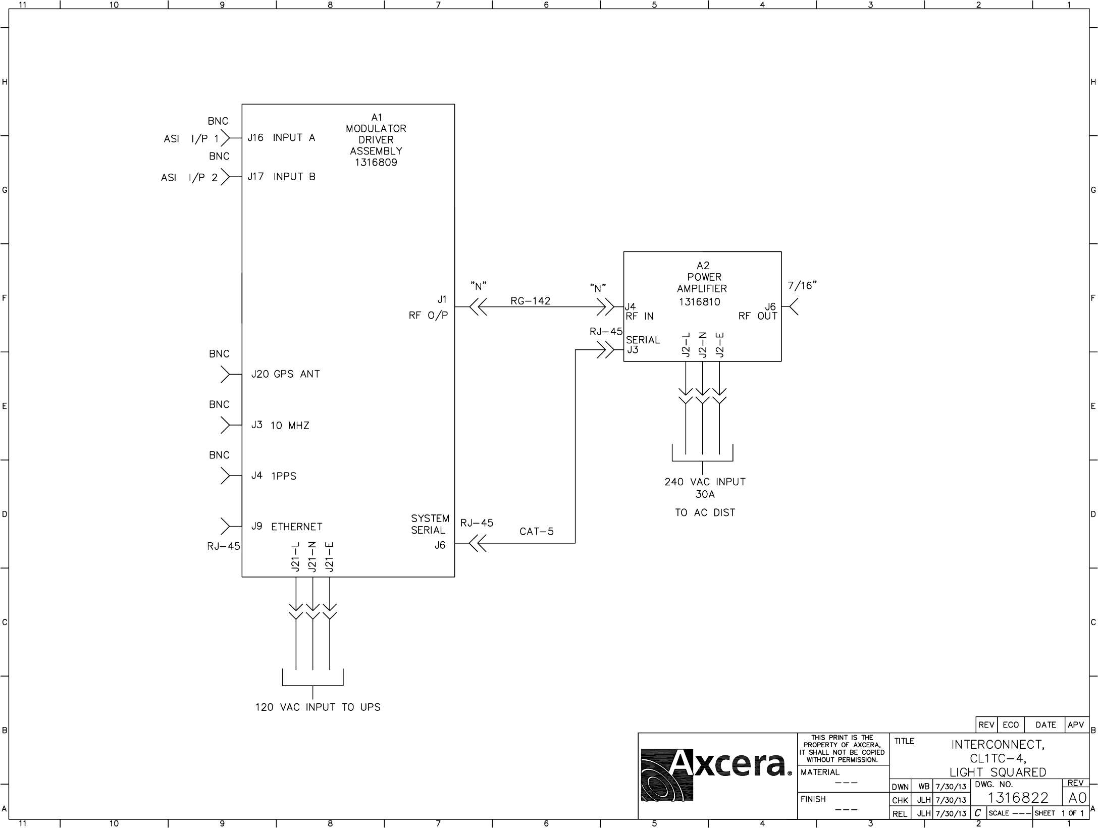
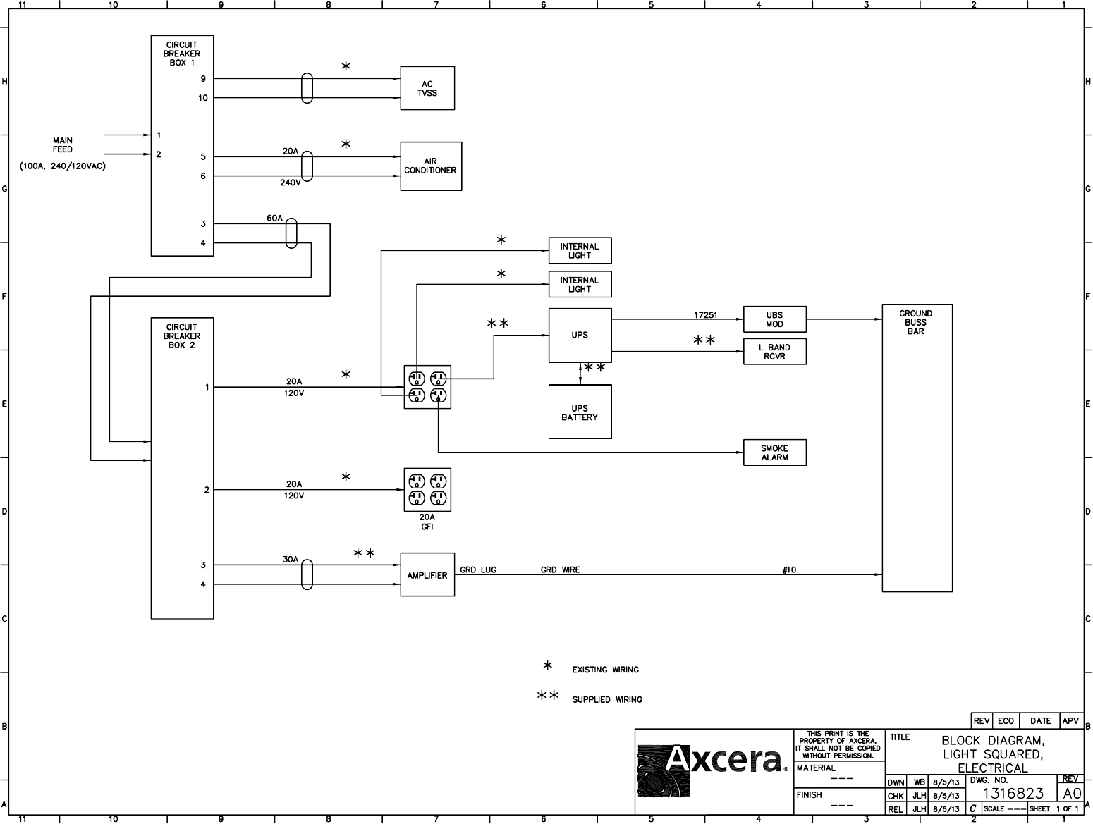
1
1
2
2
3
3
4
4
5
5
6
6
D D
C C
B B
A A
Title
Size Document Number Rev
Date: Sheet of
Drawn by:
Company
Ledger
Unique Broadband System LTD Canada
Kosta Bor
Wiring AC, DC, Control and RF Diagram Universal Modulator
03
56830-43-D01
Apr. 2013
J23-1
J23-2
J23-3
J23-4
J3-1
J3-2
J4-1
J4-2
J13
X16
X15
JP7-3
JP7-1
JP7-2
X20
J106-2
J106-1
J106-3
X5
90863-43G
PCA Universal Modulator
J1
J2
JP1-1
JP1-2
90446-02
KEYPAD
X1
CN1-1
X3
CN1-2
CN1-3
57532-02
L Band Amplifier ASSY
JP1-1
P1
JP1-3
CN1-2
CN1-3
CN1-4
90901-01
Extension Board Controller
TB1 1
TB1 2
TB1 3
TB1 4 TB1 5
TB1 6
TB1 7
75157R
POWER SUPPLY 12VDC
Antenna SAT/DVB
DB9
Reference Monitoring
56829-01
Rear Panel
L
N
GND
53065R
Power Entry
1
2
85049R
F1
FAN
1
2
85092R
F3
FAN
V+
V+
V-
V- GND
AC L
AC N
GND
50805-03
Chassis GND 50806-01
56871-01
V+
V+
V-
V-
54515-01 J1
A
K
84149R
DISPLAY
50461-01
Cable Modulator-Display
UBS P/N MFR QTY
50461-01
54515-01
50805-03
56871-01
UBS
UBS
UBS
UBS
UBS
1
1
1
1
1
Note: Length cable as required
GNDGND
59216-01
Cable RF Modulator
59217-01
Cable 1 Comunication Modulator
RF IN
RF OUT
59219-01
Cable 3 Comunication Modulator
GND
SDA
CLK
59218-01
Cable 2 Comunication Modulator
SDA
CLK
GND
59215-01
Cable RF GPS Antenna
59220-01
Cable Power +12VDC Extension board
54577-01
UBS
UBS
UBS
UBS
2
1
1
1
UBS 1
UBS 1
54577-01
59215-01
59216-01
59217-01
59218-01
59219-01
59220-01
1
2
85049R
F2
FAN
RF INRF OUT
56677-02
Filter
59216-02
Cable RF Modulator
59216-02
Cable RF Modulator
59216-02 UBS 2
PIF101
PIF102
COF1
PIF201
PIF202
COF2
PIF301
PIF302
COF3
PIF101
PIF102 PIF201
PIF202
PIF301
PIF302
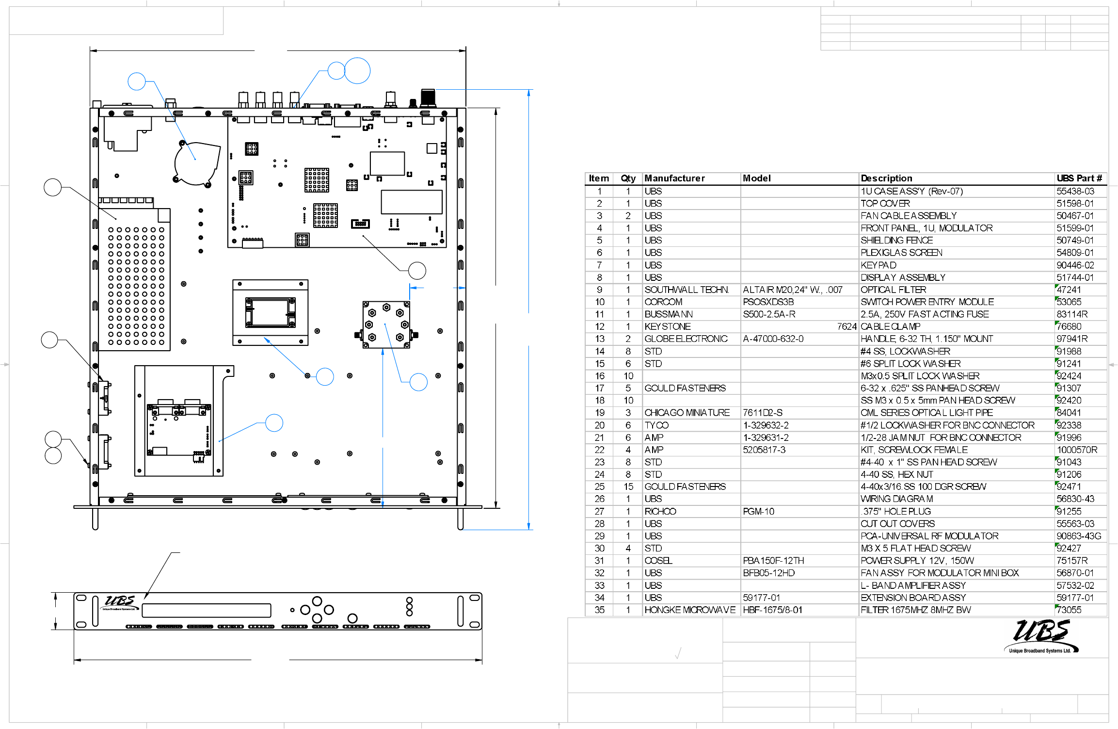
18.625
17.50
20.50
2.619
7.460
23
14
3
29
31
32
33
34
21 20
35
Item
Qty
Manufacturer
Model
Description
UBS Part #
1 1
UBS
1U CASE ASS'Y
55438-03
2 1
UBS
TOP COVER
51598-01
3 2
UBS
FAN CABLE ASSEMBLY
50467-01
4 1
UBS
FRONT PANEL, 1U, MODULATOR
51599-01
5 1
UBS
SHIELDING FENCE
50749-01
6 1
UBS
PLEXIGLAS SCREEN
54809-01
7 1
UBS
KEYPAD
90446-02
8 1
UBS
DISPLAY ASSEMBLY
51744-01
9 1
SOUTHWALL TECHN.
ALTAIR M20,24" W., .007
OPTICAL FILTER
47241
10 1
CORCOM
PSOSXDS3B
SWITCH POWER ENTRY MODULE
53065
11 1
BUSSMANN
S500-2.5A-R
2.5A, 250V FAST ACTING FUSE
83114R
12 1
KEYSTONE
7624
CABLE CLAMP
76680
13 2
GLOBE ELECTRONIC
A-47000-632-0
HANDLE, 6-32 TH, 1.150" MOUNT
97941R
14 8
STD
#4 SS, LOCKWASHER
91988
15 6
STD
#6 SPLIT LOCK WASHER
91241
16 10
M3x0.5 SPLIT LOCK WASHER
92424
17 5
GOULD FASTENERS
6-32 x .625" SS PANHEAD SCREW
91307
18 10
SS M3 x 0.5 x 5mm PAN HEAD SCREW
92420
19 3
CHICAGO MINIATURE
7611D2-S
CML SERIES OPTICAL LIGHT PIPE
84041
20 1
AMP
1-329632-2
TEETH LOCKWASHER
92338
21 1
AMP
1-329631-2
1/2-28 JAM NUT
91996
22 4
AMP
5205817-3
KIT, SCREWLOCK FEMALE
1000570R
23 8
STD
#4-40 x 1" SS PAN HEAD SCREW
91043
24 8
STD
4-40 SS, HEX NUT
91206
25 15
GOULD FASTENERS
4-40x3/16.SS 100 DGR SCREW
92471
26 1
UBS
WIRING DIAGRAM
56830-31
27 1
RICHCO
PGM-13
.500" HOLE PLUG
91625
28 1
RICHCO
PGM-10
.375" HOLE PLUG
91255
29 1
UBS
CUT OUT COVERS
55563-03
30 1
UBS
DB9 COVER
55563-01
31 1
UBS
PCA-UNIVERSAL RF MODULATOR
90863-18R
34 4
B18.6.7M - M3 x 0.5 x 5 Type I Cross Recessed FHMS --5N
35 1
COSEL
PBA150F-12TH
POWER SUPPLY 12V, 150W
75157R
36 1
UBS
BFB05-12HD
FAN ASSY FOR MODULATOR MINI BOX
56870-01
37 1
BERGQUIST
GPVOUS-.250-AC-0816-NA
Gap Pad VO Ultra Soft, size 1.08" square
98711R
38 1
UBS
L- BAND AMPLIFIER ASSY
57532-01
39 1
UBS
59177-01
EXTENSION BOARD ASSY
59177-01
40 1
SNS 59 MALE CRIMP CONNECTOR
41 1
AMP
5747871-8
DB9 CONNECTOR MALE
11035R
42 1
HBF-1675/8-01
FILTER 1675MHZ 8MHZ BW
FILTER 1675MHZ 8MHZ BW, UBS# 73055
19.000
1.73
FOR FRONT PANEL
SILKSCREN
SEE DWG
51600-43.
D
C
B
A
A
B
C
D
1
3
4
5
6
7
8
8
7
6
5
4
3
REVISIONS
REV.
DESCRIPTION
DATE
APPROVED
ECO #
APPROVALS
DATE
CAD GENERATED DRAWING DO
NOT MANUALLY UPDATE OR SCALE
DRAWN
CHECKED
RESP ENG
PROJECT
#: 243
SIZE
B
SCALE
SHEET
REV.
DWG. #
UNLESS OTHERWISE SPECIFIED DIMENSIONS
ARE IN INCHES.TOLERANCES ARE:
DECIMALS ANGLES
.XX ± .02 ± 0.5°
.XXX ± .003
FINISH
MATERIAL
OF
MACHINED SURFACES:
32
400 Spinnaker Way
Vaugham, Ontario
Canada, L4K 5Y9
Tel: (905) 669-8533
Fax (905) 669-8516
PART #
DOC. TYPE
Q.A.
WARNING, THIS DRAWING AND ITS CONTENTS ARE PROPERTY OF
UNIQUE BROADBAND SYSTEMS INC, AND SHALL NOT BE CIRCULATED
OR REPRODUCED WITHOUT THE WRITTEN PERMISSION OF UNIQUE
BROADBAND SYSTEMS INC.
NIMAL.D
1:1
1
56803-43-D01
2
08/07/2013
PRINTED ON: July-08-13
Univ. Mod DVB-H L-Band, with GPS,
and additional I/O
FIRST RELEASE
01
03
06/05/2013
02
ADD ITEM 35
10/06/2013
03
REPLACED ITEM 35
08/07/2013
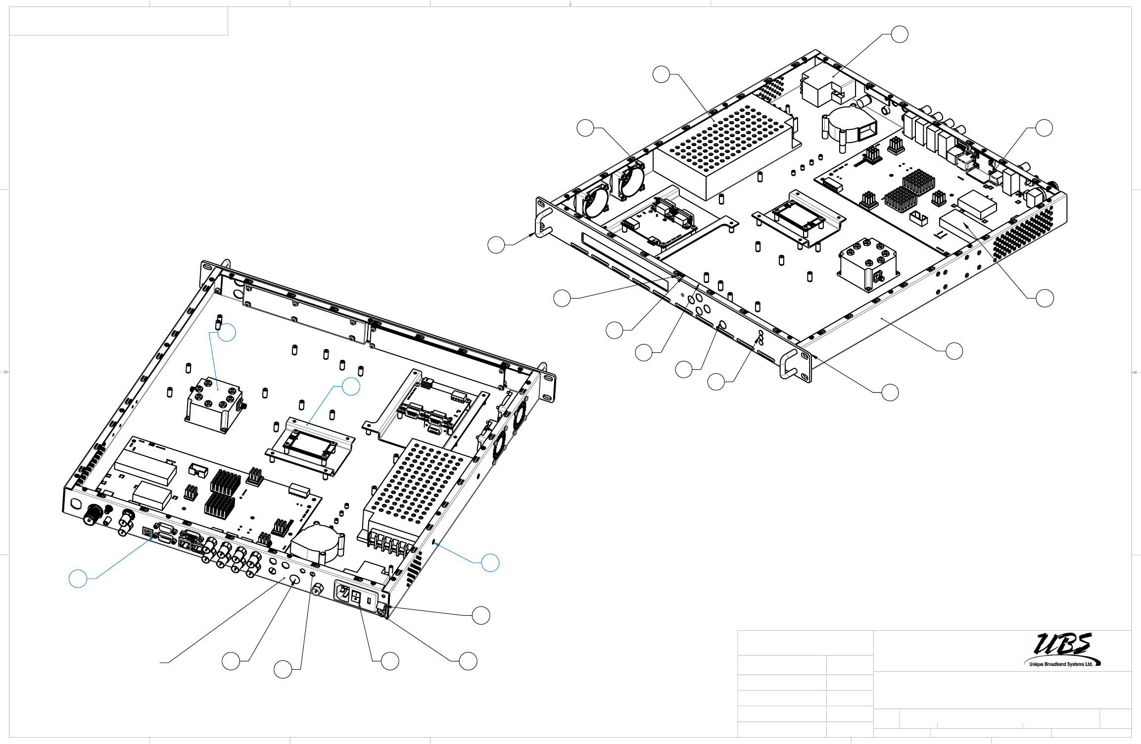
31
10
22
1
4
13
19
7
18
25
8
24
29
27 28 10 17
12
REAR PANEL
SILK SCREEN
DWG 56829-01
30
22
33
35
D
A
B
C
D
1
3
5
6
7
8
8
7
6
5
4
3
2
B
SCALE
SHEET
OF
PART #
DOC. TYPE
Q.A.
WARNING, THIS DRAWING AND ITS CONTENTS ARE PROPERTY OF
UNIQUE BROADBAND SYSTEMS INC, AND SHALL NOT BE CIRCULATED
OR REPRODUCED WITHOUT THE WRITTEN PERMISSION OF UNIQUE
BROADBAND SYSTEMS INC.
1:3.5
2
01
56803-43-D01-03
2
July-08-13
Univ. Mod DVB-H L-Band, with
GPS, and additional I/O
NIMAL.D
400 Spinnaker Way
Vaugham, Ontario
Canada, L4K 5Y9
Tel: (905) 669-8533
Fax (905) 669-8516
DWG. #
REV.
SIZE
TITLE
RESP ENG
CHECKED
DRAWN
CAD GENERATED DRAWING DO
NOT MANUALLY UPDATE OR SCALE
DATE
APPROVALS
A
B
C
243
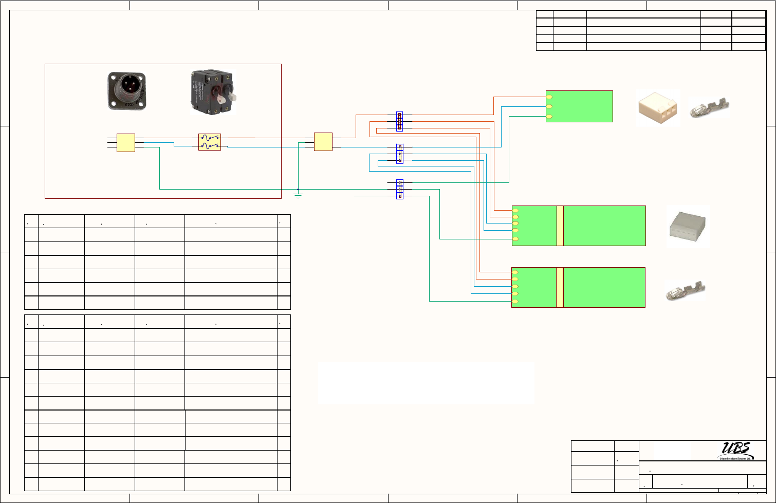
1
1
2
2
3
3
4
4
5
5
6
6
D D
C C
B B
A A
REV. DATE DESCRIPTION ECO# APPROVED
Connector 3 pin
1 1
2 2
3 3
CON1
11913R
GND
RFI POWER LINE FILTER
1 3
G
2 4
FILTER
FL1
80071
QTY
NN UBS Number MFG N#MFG Description
J1-3
J1-1
GND
75088R
POWER SUPPLY, 60W, 5V,12V
J1-4
J1-5
J1-1
J1-2
TP1
57662-01
Power Supply PCA
L1
L1
L2(N)
J1-4
J1-5
J1-1
J1-2
TP1
57662-01
Power Supply PCA
L1
L1
75205R
POWER SUPPLY, 30VDC, 1600W
75205R
POWER SUPPLY, 30VDC, 1600W
J10
J10
1
2
93024R 3081 BL005
Alpha Wire 10 AWG 600W PVC Blue 3
3
4
93476 9912 189
BELDEN 12AWG STR PVC 600V 105º Yel-Green 5
5
93019 9912 013
BELDEN 12AWG STR PVC 600V 105ó D BLUE 4
6
QTY
NN UBS Number MFG N#MFG Description
7
93023R 3081 BR005 10 AWG 600W PVC Brown 3
8
93018 9912 001
BELDEN 12AWG STR PVC 600V 105º BROWN 4
9
10
11
L1
L2
GND (N)
277VAC, 30A, 2-pole, magn. circ.brk
1
2
3
4
CB1
80197R
208 AC 2phase 30A
10608R 26-03-4030
MOLEX .156" Pitch Crimp Terminal Housing 3pos 1
11538R 09-91-0500
MOLEX .156" Pitch Crimp Terminal Housing 5pos 2
UBS # 11538R
UBS # 10608R UBS # 10658R
UBS # 10658R
10658R 08-52-0072
MOLEX .156" Pitch Crimp Terminal,Female 13
16102R 2210.0
Altech Corporation Ferrule Insulated Std 10AWG Black 2
16101R 2402.0
Altech Corporation Ferrule Insulated Std 12AWG Gray 4
92795 9918 013
BELDEN 18AWG STR PVC 300V 105º D. Blue 1
L2(N)
L2(N)
L2(N)
12
Back Plate
10090R 19067-0008
MOLEX Ring Terminal1/4" for 8AWG Wire,Red 5
B
C
B
A
UBS # 92795
UBS # 93018
92794R 9918 001
BELDEN 18AWG STR PVC 300V 105º BROWN 1
13
Title
Document Number Rev
DATE
Sheet of
Drawn by:
APPROVALS
1
B
4
400W L-Band HPA Wiring AC Diagram
05
59175-02-D01
05/15/2013
Approved by:
Size
400 Spinnaker Way
Vaughan, Ontario,
Canada, L4K 5Y9
Tel: (905) 669-8533
Checked by:
Kosta Bor
UBS # 93024R
UBS # 93023R
GND
GND
Alpha Wire
UBS # 92794R
UBS # 93019
16423R
12
TB L1
12
12
12
12
16150R
12
TB GND
12
12
16423R
12
TB L1
16423R CTS4U-N
Altech Corporation TERMINAL BLOCK 35A, DIN RAIL 6
14
16150R CGT4U TERMINAL BLOCK, 25A, DIN rail , GND 3
15 Altech Corporation
16321R CTS2.5U-N TERMINAL BLOCK, DIN RAIL 3
16 Altech Corporation
86185R CTS2.5U-N/R TERMINAL BLOCK, DIN RAIL, RED 3
17 Altech Corporation
86186R CTS2.5U-N/W TERMINAL BLOCK, DIN RAIL, White 3
18 Altech Corporation
322/07/2013 Changed copnnection HPA to Current Sense
424/07/2013 Removed connection 12VDC from Current Sense
226/06/2013 Removed small cooling fan 30VDC
TB 1
To TB 2-19
Note 1:
Recommended Hand Crimp Tool - 0638117500 for 0638117500 pins
Recommended Hand Crimp Tool - 1212045 for ferrules
Recommended Hand Crimp Tool - MAC 2210 for ring terminals
507/31/2013 Changed terminal connection
PICB101
PICB102
PICB103
PICB104
COCB1
PICON101
PICON102
PICON103
COCON1
PIFL101
PIFL102
PIFL103
PIFL104
PIFL10G
COFL1
PITB?01PITB?02
COTB?
PITB?01PITB?02
PITB?01PITB?02
PITB?01PITB?02
PITB?01PITB?02
PITB?01PITB?02
PITB GND01 PITB GND02
COTB GND
PITB L101 PITB L102
COTB L1
PICON103
PIFL10G
PITB?01
PICB101
PICON101
PICB102
PICON102
PICB103
PIFL101
PICB104
PIFL102
PICON101
PICON102
PICON103
PIFL103
PITB L101
PIFL104
PITB L101
PITB?01
PITB?01
PITB?01
PITB?01
PITB?01
PITB?02
PITB?02
PITB?02
PITB?02
PITB?02
PITB?02
PITB GND01 PITB GND02
PITB L102
PITB L102
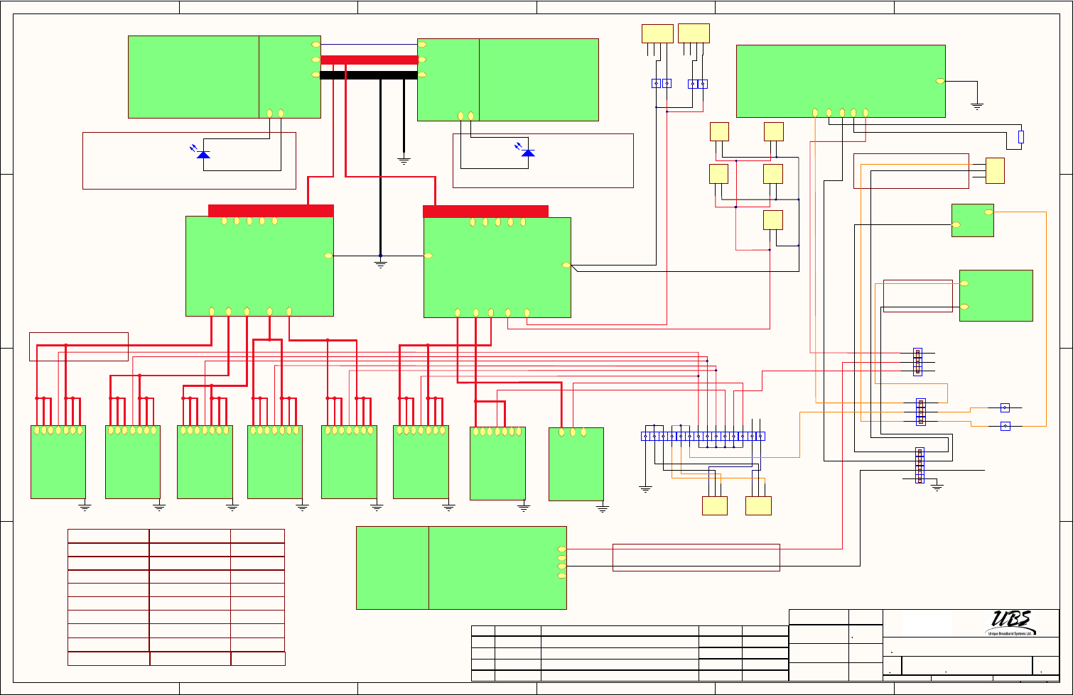
1
1
2
2
3
3
4
4
5
5
6
6
D D
C C
B B
A A
J4-5
J4-6
98727R
Display Board
90945-01
AGC Board
J17-3
J17-1
J17-2
J17-4
90927-01
MiniController
TB9
TB7
TB5
TB3
TB1
TB10
TB8
TB6
TB4
TB2
GND
90934-01
PCA, Current Sense 1
TB9
TB7
TB5
TB3
TB1
TB10
TB8
TB6
TB4
TB2
GND
GND
90934-02
PCA, Current Sense 2
1
2
3
35919
TS1
TermoSensor
J2-1
J2-2
J2-3
J2-4
J2-6
GND
75088R
Power Supply 60W 5/12 VDC
75205R
Power Supply 30VDC
75205R
Power Supply 30VDC
1
2
3
4
5
6
7
90958-01
HPA2
GND
1
2
3
4
5
6
7
90958-01
HPA3
1
2
3
4
5
6
7
90958-01
HPA4
1
2
3
4
5
6
7
90958-01
HPA5
1
2
3
4
5
6
7
90958-01
HPA6
1
2
3
4
5
6
7
90958-01
HPA1
1
2
3
4
5
6
7
90958-01
Driver
1
2
3
90959-01
Pre-Driver
+5 VDC
+12VDC
RTN VDC
RTN VDC
15 Ohm
R1
31471R
GND GND GND GND GND GND GND
+12VDC
+12VDC
+30VDC
+12VDC
+ OUT
- OUT
J3-1
J6
J3-2
57662-01
Power Supply PCA
+ OUT
- OUT
J6
J3-1
J3-2
57662-01
Power Supply PCA
+5 VDC
GND
1
2
3
35919
TS2
TermoSensor
LED Indicator GREEN
D2
84038
Back Plate
LED Indicator GREEN
D1
84038
+5 VDC
+5 VDC
UBS # 92097R
UBS # 92101R UBS # 92101R
59189-01
Cable Termo Sensor HPA
59190-01
CABLE DC Power HPA
UBS P/N MFR QTY
59190-01
59189-01
59191-01
59192-01
59194-01
UBS
UBS
UBS
UBS
UBS
6
3
2
1
1
59191-01
LED Indicator AC Power Supply
Back Plate
59192-01
Cable Power Supply +12VDC
59194-01
Cable Power Display Board
93040R
93039R
Dongguan QS electronic 2
2
Dongguan QS electronic
92097R 1
BELDEN
GND 1
2
3
35919
TS3
TermoSensor
11
22
33
44
55
66
77
88
99
10 10
11 11
12 12
TB3
+5VDC
UBS # 92822R
93034R 1
QUALTEC ELECTRONICS
1
2
85102
F5
FAN
1
2
85102
F6
FAN
1
2
85102
F7
FAN
Title
Document Number Rev
DATE
Sheet of
Drawn by:
APPROVALS
2
B
4
400W L-Band HPA Wiring DC Diagram
0559175-02-D01
05/15/2013
Approved by:
Size
400 Spinnaker Way
Vaughan, Ontario,
Canada, L4K 5Y9
Tel: (905) 669-8533
Checked by:
Kosta Bor
Scale : NONE
GND
UBS # 93039R
UBS # 93040R
1
2
85102
F3
FAN
1
2
85102
F4
FAN
J5-1
J6-6
DB9
REAR PLATE
To FAN 1, 2
1
2
3
4
85103
F1
FAN
UBS # 93039R
UBS # 93040R
1
2
3
4
85103
F2
FAN
12
12
12
12
12
TB RTN VDC
16321R
12
12
12
GND
GND
86185R
12
TB 12VDC
86186R
12
TB 5VDC
REV. DATE DESCRIPTION ECO# APPROVED
226/06/2013 Removed small cooling fan 30VDC
322/07/2013 Changed connection HPA to Current Sense
+5 VDC
424/07/2013 Removed connection 12VDC from Current Sense
4
3
4
3
TB7 TB6
TB 2
13 13
14 14
+5DC
RTN DC
GND
To TB 1-4
TB4-8
TB5-8
507/31/2013 Changed terminal connection
PID101
PID102
COD1
PID201
PID202
COD2
PIF101
PIF102
PIF103 PIF104
COF1
PIF201
PIF202
PIF203
PIF204
COF2
PIF301 PIF302
COF3
PIF401
PIF402
COF4
PIF501
PIF502
COF5
PIF601 PIF602
COF6
PIF701 PIF702
COF7
PIR101
PIR102
COR1
PITB301
PITB302 PITB303
PITB304
PITB305 PITB306
PITB307
PITB308
PITB309
PITB3010
PITB3011 PITB3012
COTB3
PITB 5VDC01
PITB 5VDC02
COTB 5VDC
PITB 12VDC01
PITB 12VDC02
COTB 12VDC
PITB?01PITB?02
COTB?
PITB?01PITB?02
PITB?01
PITB?02
PITB?01
PITB?02
PITB?01
PITB?02
PITB?01
PITB?02
PITB?01
PITB?02 PITB?01
PITB?02
PITB?01PITB?02
PITB?01PITB?02
PITB?01PITB?02
PITB?01
PITB?02
PITB?01PITB?02
PITB?01
PITB?02
PITB?01
PITB?02
PITB RTN VDC01 PITB RTN VDC02
COTB RTN VDC
PITS101
PITS102
PITS103
COTS1
PITS201
PITS202
PITS203
COTS2
PITS301
PITS302
PITS303
COTS3
NL3NL4
NL13 NL14
PITB301
PITB?02
PID101
PID102
PID201
PID202
PIF101
PIF102
PIF103
PITB?02
PIF104
PIF201
PIF202
PIF203
PITB?02
PIF204
PITB?02
PIF301 PIF401
PIF501
PIF601
PIF701
PIF302
PIF402
PIF502 PIF602
PIF702
PIR101
PIR102
PITB301
PITB302 PITB303
PITB302
PITS102
PITB303
PITS202
PITB304 PITB305 PITB306
PITB304
PITS101
PITB305
PITS201
PITB306
PITB?01
PITB307
PITB307
PITB308 PITB309
PITB3010
PITB3011 PITB3012
PITB308 PITB309
PITB3010 PITB3011
PITB?01
PITB3012
PITB 5VDC01
PITB 5VDC02
PITB 12VDC01
PITB 12VDC02
PITB?01
PITB?01
PITB?01
PITS301
PITB?01
PITB?01
PITB?01
PITB?01
PITB?01
PITS103
PITB?01
PITS203
PITB?01
PITB?01
PITB?02
PITB?02
PITB?02
PITB?02
PITB?02
PITB?02
PITB?02PITB?02
PITB?02
PITB RTN VDC01 PITB RTN VDC02
PITS302
PITS303
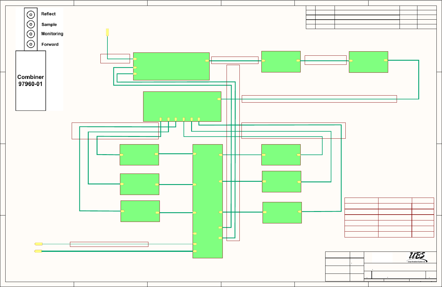
1
1
2
2
3
3
4
4
5
5
6
6
D D
C C
B B
A A
RF IN RF OUT
RF F
RF R
90945-01
AGC BOARD
RF IN RF OUT
90959-01
PRE-DRIVER
RF IN RF OUT
90958-01
DRIVER
RF IN
RF OUT 1
RF OUT 2
RF OUT 3
RF OUT 4
RF OUT 5
RF OUT 6
73054
SPITER 6 WAY
RF IN RF OUT
90958-01
HPA1
RF OUT
RF IN 1
RF IN 2
RF IN 3
RF IN 4
RF IN 6
RF IN 5
RF SMPL
RF FRW
RF REFL
RF MONITOR
97960-01
COMBINER
J7
J1
RF IN RF OUT
90958-01
HPA2
RF IN RF OUT
90958-01
HPA3
RF INRF OUT
90958-01
HPA4
RF IN
RF OUT
90958-01
HPA5
RF IN
RF OUT
90958-01
HPA6
RF from MODULATOR
Forward
Reflect
Sample
Forward
Reflect
Soldering
Soldering
Soldering
Soldering
Soldering
Soldering
59199-04
Cable RF SMA connectors
UBS P/N MFR QTY
59199-01 UBS 1
59199-02
Cable RF SMA connectors
59199-01
Cable RF SMA connectors
59199-02 UBS 2
59199-06
Cable RF SMA connectors
59199-06
Cable RF SMA connectors
59199-02
Cable RF SMA connectors
59199-03
Cable RF SMA connectors
59199-03 UBS 1
Title
Document Number Rev
DATE
Sheet of
Drawn by:
APPROVALS
4
B
4
400W L-Band HPA Wiring RF Diagram
05
59175-02-D01
05/15/2013
Approved by:
Size
400 Spinnaker Way
Vaughan, Ontario,
Canada, L4K 5Y9
Tel: (905) 669-8533
Checked by:
Kosta Bor
Scale : NONE
REV. DATE DESCRIPTION ECO# APPROVED
RF OUT
RF IN
J6
59199-04 UBS 2
59199-05
Cable RF SMA - N-Type connectors
2 26/06/2013 Added RF Monitor port
322/07/2013 Changed copnnection HPA to Current Sense
424/07/2013 Removed connection 12VDC from Current Sense
507/31/2013 Changed terminal connection
59199-05 UBS 1
59199-06 UBS 6
POJ7
POJ1
POJ6
POJ1
POJ6
POJ7
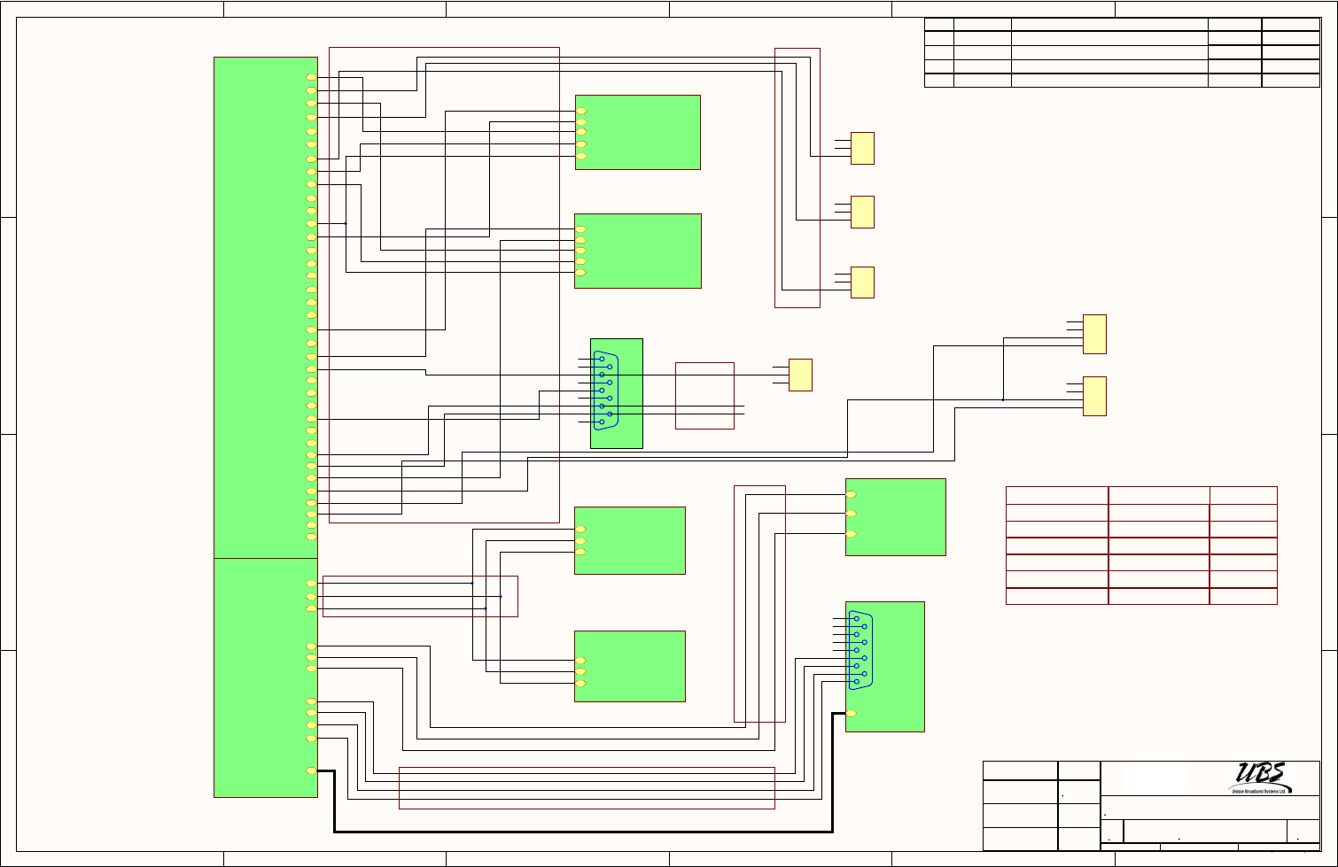
1
1
2
2
3
3
4
4
5
5
6
6
D D
C C
B B
A A
J2-37
J2-35
J2-34
J2-33
J2-31
J2-30
J2-32
J2-36
J2-29
J2-28
J2-14
J2-15
J2-16
J2-17
J2-18
J2-19
J2-23
J2-24
J2-25
J2-26
J2-27
J2-20
J2-21
J2-22
J2-1
J2-2
J2-3
J2-4
J2-5
J2-6
J2-7
J2-8
J2-9
J2-10
J2-11
J2-12
J2-13
90945-01
AGC Board
J3
REAR PLATE
J2-4
J2-5
J2-1
J2-2
J2-3
57662-01
Power Supply 1 PCA
1
2
335919
TS1
TermoSensor
1
2
335919
TS2
TermoSensor
J2-4
J2-5
J2-1
J2-2
J2-3
57662-01
Power Supply 2 PCA
J23-4
J23-3
J23-2
J16-2
J16-1
J16-4
J16-3
J15-1
J15-3
J17-4
Mini USB
90927-01
MiniController
X1-1
X1-3
X1-2
90934-01
PCA, Current Sense
X1-1
X1-3
X1-2
90934-02
PCA, Current Sense
J2-1
J2-2
J2-3
84126R
Display Board
GRD
TXD
RXD
TXD
RXD
GRD
Temperature Sensor 1
Temperature Sensor 2
Current Monitoring 2
AC 1 OK
Voltage Monitoring 1
12C interface. SCL.
12C interface. SDA.
Enable Power supply
GND
GND
GND
GND
DATA
CLK
GND
DATA
CLK
GND
DATA
CLK
GND
Current Monitoring
Current Monitoring
Enable Power supply
Enable Power supply
Voltage Monitoring
Voltage Monitoring
AC OK
AC OK
GND
GND
59189-01
Cable Termo Sensor HPA
59198-01
Cable RS485 HPA
59197-01
Cable RS232 Displey Board
59195-02
Cable DB37 connector HPA
59196-01
Cable communication PCA, Current Sense
UBS P/N MFR QTY
59195-02
59196-01
59197-01
59198-01
58939-01
UBS
UBS
UBS
UBS
UBS
1
1
1
1
1
Temperature Sensor 3
1
2
335919
TS3
TermoSensor
92419 1
Current Monitoring 1
Voltage Monitoring 2
AC 2 OK
Title
Document Number Rev
DATE
Sheet of
Drawn by:
APPROVALS
3
B
4
400W L-Band HPA Wiring Control Diagram
0559175-02-D01
05/15/2013
Approved by:
Size
400 Spinnaker Way
Vaughan, Ontario,
Canada, L4K 5Y9
Tel: (905) 669-8533
Checked by:
Kosta Bor
Scale : NONE
REV. DATE DESCRIPTION ECO# APPROVED
UBS # 92419
REAR PLATE
1
2
3
4
5
6
7
8
9
J5
DB9 (F)
USB 2.0 A
1
2
3
4
5
6
7
8
9
J4
DB9 (M)
Temperature Sensor 4
DOOR Sensor
Smoke Alarm Sensor
FAN Tachometer 1
DOOR Sensor
Smoke Alarm Sensor
1
2
3
LM60CIZ/NOPB
95507R
TS4
59195-02
Cable DB37 connector HPA
FAN Control
PWM
FAN Tachometer 2
TACHO
TACHO
1
2
3
485103
F1
FAN
1
2
3
485103
F2
FAN
TACHO
PWM
TACHO
322/07/2013 Changed copnnection HPA to Current Sense
424/07/2013 Removed connection 12VDC from Current Sense
226/06/2013 Removed small cooling fan 30VDC
507/31/2013 Changed terminal connection
PIF101
PIF102
PIF103
PIF104
COF1
PIF201
PIF202
PIF203
PIF204
COF2
PIJ401
PIJ402
PIJ403
PIJ404
PIJ405
PIJ406
PIJ407
PIJ408
PIJ409
COJ4
PIJ501
PIJ502
PIJ503
PIJ504
PIJ505
PIJ506
PIJ507
PIJ508
PIJ509
COJ5
PITS101
PITS102
PITS103
COTS1
PITS201
PITS202
PITS203
COTS2
PITS301
PITS302
PITS303
COTS3
PITS401
PITS402
PITS403
COTS4
PIF101
PIF102
PIF103
PIF203
PIF104
PIF201
PIF202
PIF204
PIJ401
PIJ402
PIJ403
PIJ404
PIJ405
PIJ406
PIJ407
PIJ408
PIJ409
PIJ501
PIJ502
PIJ503
PIJ504
PIJ505
PIJ506
PIJ507
PIJ508
PIJ509
PITS101
PITS102
PITS103
PITS201
PITS202
PITS203
PITS301
PITS302
PITS303
PITS401
PITS402
PITS403
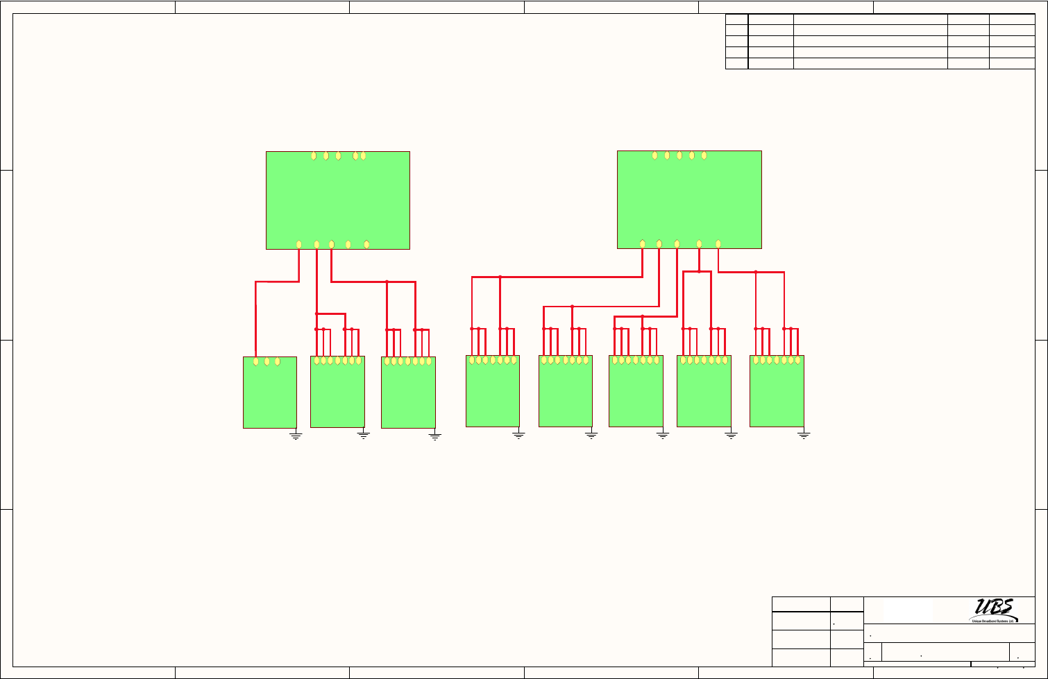
1
1
2
2
3
3
4
4
5
5
6
6
D D
C C
B B
A A
TB9
TB7
TB5
TB3
TB1
TB10
TB8
TB6
TB4
TB2
90934-01
PCA, Current Sense 1
TB9
TB7
TB5
TB3
TB1
TB10
TB8
TB6
TB4
TB2
90934-02
PCA, Current Sense 2
1
2
3
4
5
6
7
90958-01
HPA2
1
2
3
4
5
6
7
90958-01
HPA3
1
2
3
4
5
6
7
90958-01
HPA4
1
2
3
4
5
6
7
90958-01
HPA5
1
2
3
4
5
6
7
90958-01
HPA6
1
2
3
4
5
6
7
90958-01
HPA1
1
2
3
4
5
6
7
90958-01
Driver
1
2
3
90959-01
Pre-Driver GND GND GND GND GND
GND
GND
+30VDC
GND
+30VDC
HPA2
HPA3
HPA4
HPA5
HPA6
Pre-Driver
Driver
HPA1
FAN:3,4,5,6,7
FAN:1,2
Title
Document Number Rev
DATE
Sheet of
Drawn by:
APPROVALS
1
B
4
400W L-Band HPA Schematic Connection to Current Sense
05
59175-02-D01
05/15/2013
Approved by:
Size
400 Spinnaker Way
Vaughan, Ontario,
Canada, L4K 5Y9
Tel: (905) 669-8533
Checked by:
Kosta Bor
REV. DATE DESCRIPTION ECO# APPROVED
322/07/2013 Changed copnnection HPA to Current Sense
424/07/2013 Removed connection 12VDC from Current Sense
226/06/2013 Removed small cooling fan 30VDC
507/31/2013 Changed terminal connection
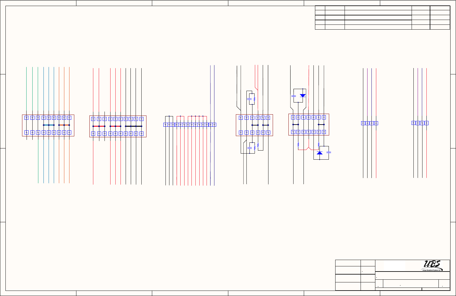
1
1
2
2
3
3
4
4
5
5
6
6
D D
C C
B B
A A
C1
D1
R2 R3
Rear Plate DB9 J5-4
From TB2-10
R6
R4
C3
AGC Board DB37 J2-35
From TB2-8
To TB6-2 (PWM)
C2
D2
1
3
5
7
9
11
13
2
4
6
8
10
12
14
R5
C4
2
4
6
8
10
12
1
3
5
7
9
11
2
4
6
8
10
12
1
3
5
7
9
11
16
18
15
17
13 14
Filter L1
Filter L2
Power Supply 1 L1
Power Supply 1 L1
Power Supply 1 L2
Power Supply 1 L2
L2 L1
GND
TB1
Power Supply 2 L1
Power Supply 2 L1
Power Supply 2 L2
Power Supply 2 L2
Power Supply 3 L1
Power Supply 3 L1
Power Supply 3 GND
Power Supply 1 GND
To AC GND pin
To TB 2-19
2
4
6
8
10
12
1
3
5
7
9
11
16
18
15
17
13 14
To DB9(M) J5-6
To Display J4-6
To TB5-8
TB2
To J2-3 Power Supply 3
To TB3-6
To Thermosensot 3 pin1
To DC GND pin
From J2-6 Power Supply 3 To Mini Controller J17-1
To TB3-11
20
19
12VDC 5VDC RTN DC
From J2-1 Power Supply 3
To Display J4-5
To Thermosensot 3 pin2
To Mini Controller J17-3
TB5
TB4
To TB1-4
11
22
33
44
55
66
11
22
33
44
55
66
77
88
TB3
1
3
5
7
9
11
14
12
13
10
2
4
6
8
To TB2-4
12VDC
5VDC
RTN DC
To TB2-9
To Pre-driver pin 12VDC
To ThermoSensor 1 pin1
To ThermoSensor 2 pin1
To ThermoSensor 1 pin2
To ThermoSensor 2 pin2
To DC GND pin
FromThermoSensor 1 pin3
FromThermoSensor 2 pin3
To AGC Board DB37 J2-2
To AGC Board DB37 J2-4
To HPA1, 2 pin4
To HPA3, 4 pin4
To HPA5, 6 pin4
To Driver pin4
TB6 TB7
2
4
1
3
2
4
1
3
From Current Sense TB10
From Current Sense TB10
From Current Sense TBGND
From Current Sense TBGND
To TB7-2 (PWM)
From TB4-10 (PWM)
From TB4-12 (PWM)
To TB6-1 (TACHO2)
To TB7-1 (TACHO1)
From TB4-3 (TACHO2)
From TB4-2 (TACHO1)
Title
Document Number Rev
DATE
Sheet of
Drawn by:
APPROVALS
1
B
4
400W L-Band HPA Diagram Terminals Connection
05
59175-02-D01
05/15/2013
Approved by:
Size
400 Spinnaker Way
Vaughan, Ontario,
Canada, L4K 5Y9
Tel: (905) 669-8533
Checked by:
Kosta Bor
REV. DATE DESCRIPTION ECO# APPROVED
322/07/2013 Changed copnnection HPA to Current Sense
424/07/2013 Removed connection 12VDC from Current Sense
226/06/2013 Removed small cooling fan 30VDC
AGC Board DB37 J2-33
AGC Board DB37 J2-34
AGC Board DB37 J2-30
AGC Board DB37 J2-31
Rear Plate DB9 J5-8
Rear Plate DB9 J5-9
Rear Plate DB9 J5-3
30VDC red wire
30VDC red wire
RTN 30VDC blue wire
RTN 30VDC blue wire
PWM violet wire
PWM violet wire
TACHO white wire
TACHO white wire
To TB4-8
FAN 2 FAN 1
To R1
To DB9(M) J5-1
507/31/2013 Changed terminal connection
PIC101
PIC102
COC1
PIC201
PIC202
COC2
PIC301
PIC302
COC3
PIC401
PIC402
COC4
PID101
PID102
COD1
PID201
PID202
COD2
PIR201
PIR202
COR2
PIR301
PIR302
COR3
PIR401
PIR402
COR4
PIR501
PIR502
COR5
PIR601
PIR602
COR6
PITB?01
PITB?02
COTB?
PITB?01
PITB?02
PITB?01
PITB?02
PITB?01
PITB?02
PITB?01
PITB?02
PITB?01
PITB?02
PITB?01
PITB?02
PITB?01
PITB?02
PITB?01
PITB?02 PITB?03
PITB?04 PITB?05
PITB?06
PITB?07 PITB?08
PITB?01 PITB?02
PITB?03 PITB?04
PITB?05 PITB?06
PITB?01
PITB?02
PITB?01
PITB?02
PITB?01
PITB?02
PITB?01
PITB?02
PITB?01
PITB?02
PITB?01
PITB?02 PITB?01
PITB?02
PITB?01
PITB?02
PITB?01
PITB?02
PITB?01
PITB?02
PITB?01
PITB?02
PITB?01
PITB?02
PITB?01
PITB?02
PITB?01
PITB?02
PITB?01
PITB?02
PITB?01
PITB?02
PITB?01
PITB?02
PITB?01
PITB?02
PITB?01
PITB?02
PITB?01
PITB?02
PITB?01
PITB?02
PITB?01
PITB?02
PITB?01
PITB?02
PITB?01
PITB?02 PITB?01
PITB?02
PITB?01
PITB?02
PITB?01
PITB?02
PITB?01
PITB?02
PITB?01
PITB?02
PITB?01
PITB?02
PITB?01
PITB?02
PITB?01
PITB?02
PITB?01
PITB?02
PITB?01
PITB?02
PITB?01
PITB?02
PITB?01
PITB?02 PITB?01
PITB?02
PITB?01
PITB?02 PITB?01
PITB?02
PITB?01
PITB?02
PITB?01
PITB?02
PITB?01
PITB?02
PITB?01
PITB?02
PITB?01
PITB?02
PITB?01
PITB?02
PITB?01
PITB?02
PITB?01
PITB?02
PITB?01
PITB?02
PITB?01
PITB?02
PITB?01
PITB?02 PITB?01
PITB?02
PITB?01
PITB?02
PITB?01
PITB?02
PITB?01
PITB?02
PITB?01
PITB?02
PITB?01
PITB?02
PITB?01
PITB?02
PITB?01
PITB?02
PITB?01
PITB?02
PITB?01
PITB?02
PITB?01
PITB?02
PITB?01
PITB?02
PITB?01
PITB?02
PITB?01
PITB?02
PITB?01
NL1
PITB?01
PITB?02
NL2
PIR201
PITB?01
NL3
PITB?01
NL4
PITB?01
NL5
NL6
PITB?01
NL7
NL8
PIC201
PID201
PITB?01
NL9
PITB?02
NL10
PIR301
PITB?01
PITB?03
NL11
PITB?04
NL12
PIC202
PID202
PITB?01
NL13
PITB?06
NL14
NL15
NL16
NL17
NL18
NL19
NL20
PIC101
PID101
PIC102
PID102
PITB?02
PIC301
PIR401
PITB?01
PIC302
PIR402
PITB?01
PIC401
PIR501
PITB?02
PIC402 PIR502
PITB?02
PIR202 PIR302
PIR601
PITB?01
PIR602
PITB?01
PITB?01
PITB?02
PITB?01
PITB?02
PITB?01
PITB?02
PITB?01
PITB?02
PITB?01
PITB?02
PITB?01
PITB?01
PITB?02
PITB?01
PITB?02
PITB?01
PITB?02
PITB?01
PITB?01
PITB?02
PITB?01PITB?01
PITB?02 PITB?03
PITB?01PITB?01
PITB?01
PITB?01
PITB?02
PITB?01
PITB?01
PITB?01
PITB?01
PITB?02
PITB?01
PITB?01PITB?01
PITB?01
PITB?02
PITB?01
PITB?01PITB?01
PITB?01
PITB?02
PITB?01
PITB?01
PITB?01
PITB?01
PITB?02
PITB?01
PITB?01
PITB?02
PITB?01
PITB?01
PITB?02
PITB?01
PITB?01
PITB?02
PITB?01
PITB?02PITB?02PITB?02PITB?02
PITB?02
PITB?02
PITB?02PITB?02
PITB?02
PITB?02
PITB?02PITB?02
PITB?02
PITB?02
PITB?02
PITB?02
PITB?02
PITB?02
PITB?02
PITB?02
PITB?02
PITB?02PITB?02PITB?02PITB?02
PITB?02
PITB?02
PITB?02
PITB?02
PITB?02
PITB?02
PITB?02
PITB?02
PITB?02PITB?02
PITB?02
PITB?02
PITB?02
PITB?03
PITB?03
PITB?04PITB?04
PITB?05
PITB?06
PITB?04 PITB?05
PITB?05
PITB?05
PITB?06
PITB?06
PITB?07 PITB?08
PITB?07 PITB?08
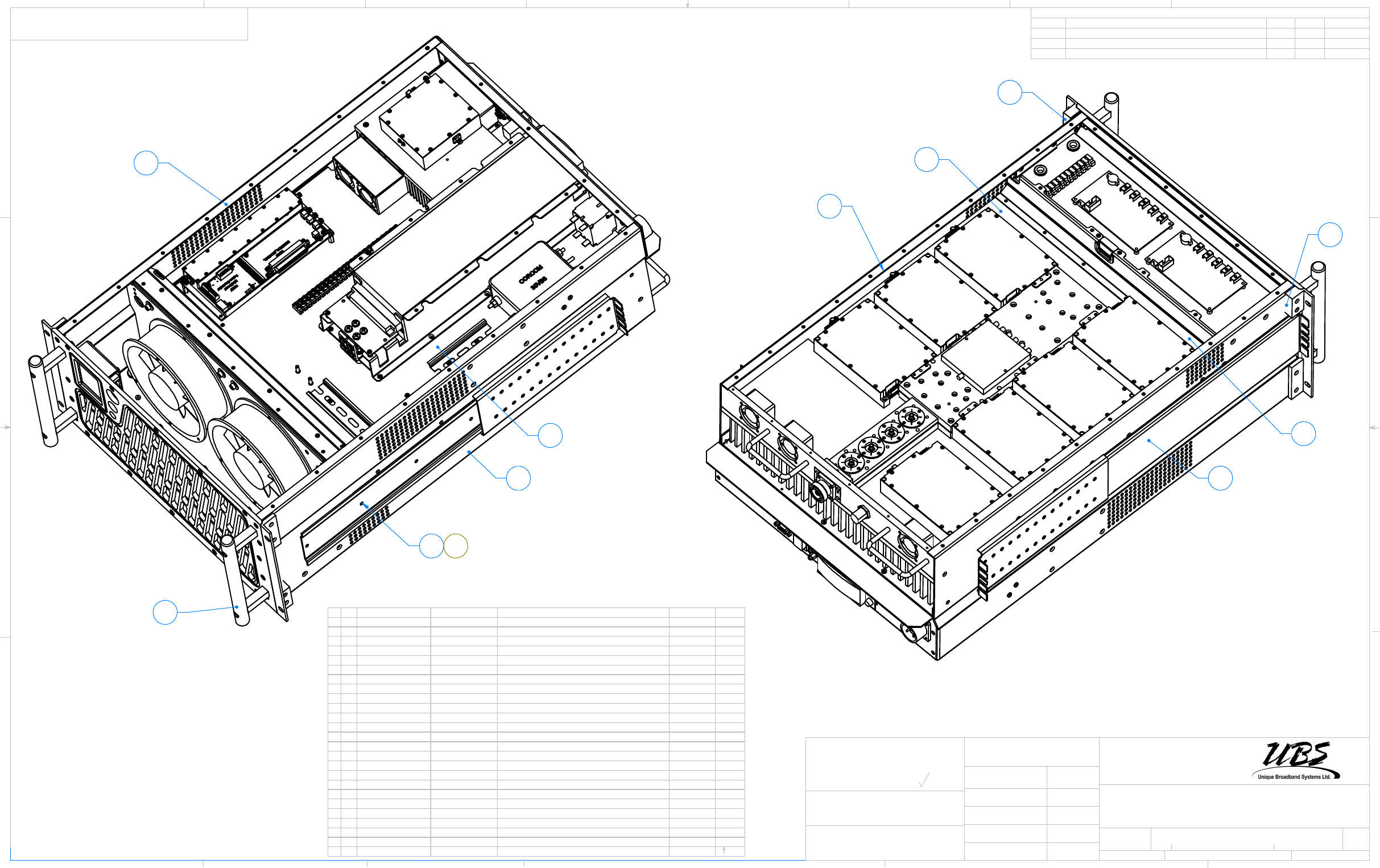
6
5
10
13
15
16
2
3
8
1
14
9
02 07 13
SEE NOTE
1:4 2
03
59132-01-D01
1
17.10.2012
August-06-13
400W L BAND HPA ASSY
FIRST RELEASE
01
CREATED May-23-13 4:47:24 PM
H. VASSELL
RELOCATION OF COMPONENTS ON HSK AND P/S SIDE02
ADDED SHT 2
03 23 07 13
Vaughan, Ontario
D
C
B
A
A
B
C
D
1
345678
876543 2
REVISIONS
REV. DESCRIPTION DATE APPROVEDECO #
APPROVALS DATE
Canada, L4K 5Y9
NOT MANUALLY UPDATE OR SCALE
DRAWN
CHECKED
RESP ENG
TITLE
SIZE
B
SCALE SHEET
REV.
DWG. #
CAD GENERATED DRAWING DO
ARE IN INCHES.TOLERANCES ARE:
UNLESS OTHERWISE SPECIFIED DIMENSIONS
Tel: (905) 669-8533
.XXX ± .003
FINISH
MATERIAL
OF
MACHINED SURFACES: 32
.XX ± .02 ± 0.5°
DECIMALS ANGLES
Q.A. DOC. TYPE
Fax (905) 669-8516
PART #
400 Spinnaker Way
WARNING, THIS DRAWING AND ITS CONTENTS ARE PROPERTY OF
UNIQUE BROADBAND SYSTEMS INC, AND SHALL NOT BE CIRCULATED
OR REPRODUCED WITHOUT THE WRITTEN PERMISSION OF UNIQUE
BROADBAND SYSTEMS INC.
Item
Qty Manufacturer Model Description UBS P/n
1 1 UBS FRONT PANEL DEVAS HPA ASSY 56646-01
2 1 AXCERA SIDE WALL LEFT 56664-01
3 1 UBS SIDE WALL RIGHT 56670-01
4 1 UBS TOP COVER (NOT SHOWN) 56650-01
5 1 UBS LEFT MOUNTING BRACKET 56740-01
6 1 UBS RIGHT MOUNTING BRACKET 56741-01
7 1 UBS FAN ASSEMBLY 56671-01
8 2 UBS SPACER 56663-01
9 2 STD #6-32x 1/4" SS FL HD SCREW 82 DEGREES 91025
10 2 GENERAL DEVICES SLIDE CHASSIS 20"LG (PAIR) 95546R
11 2 STD #6-32x 3/8" SS FL HD SCREW 91135
12 2 STD #6-32x 1/4" SS FL HD SCREW 91111
13 1 UBS HIGH PWR AMP SUB ASSY 59135-01
14 1 UBS CONTROL MODULE 59207-01
15 1 UBS CONTROLLER PLATE 56727-01
16 1 UBS HIGH PWR AMP COVER (sht 2) 59277-01
17 1 UBS CONTROL MODULE COVER (sht 2) 56630-01
18 2 WECO 323-HDS/06 TERMINAL BLOCK-6 POLE 11963R
19 1 EOS VLT60-3000 POWER SUPPLY 12V,-12V,5V 75088
20 2 RICHCO HG-6 3/8 RUBBER GROMETT 98682
21 1 UBS WIRING DIAGRAM 59190-01
22 2 GENERAL DEVICES SLIDE MTG. BKT B307-2 95547R
23 1 UBS OUTPUT SUPPORT PLATE w/ N-TYPE (sht 2) 59319-01
24 1 UBS NEW REAR PANEL 59321-01
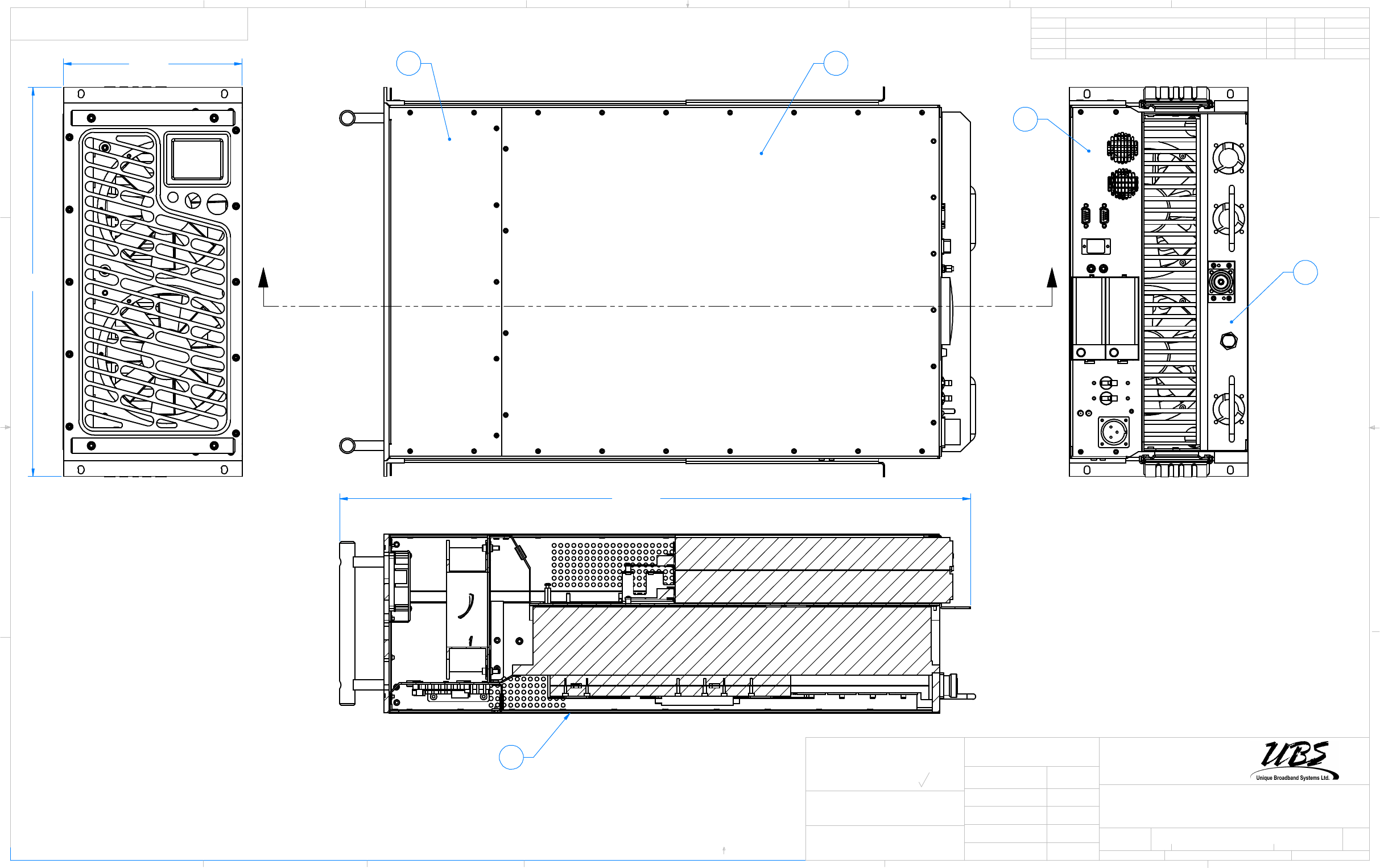
SECTION F-F
16
30.80
18.99
8.72
23
24
174
FF
CREATED May-23-13 4:47:24 PM
SEE NOTE
1:4 2
03
59132-01-D01
2
07.12.2012
August-06-13
FIRST RELEASE
01
400W L BAND HPA ASS'Y
Vaughan, Ontario
D
C
B
A
A
B
C
D
1
345678
876543 2
REVISIONS
REV. DESCRIPTION DATE APPROVEDECO #
APPROVALS DATE
Canada, L4K 5Y9
NOT MANUALLY UPDATE OR SCALE
DRAWN
CHECKED
RESP ENG
TITLE
SIZE
B
SCALE SHEET
REV.
DWG. #
CAD GENERATED DRAWING DO
ARE IN INCHES.TOLERANCES ARE:
UNLESS OTHERWISE SPECIFIED DIMENSIONS
Tel: (905) 669-8533
.XXX ± .003
FINISH
MATERIAL
OF
MACHINED SURFACES: 32
.XX ± .02 ± 0.5°
DECIMALS ANGLES
Q.A. DOC. TYPE
Fax (905) 669-8516
PART #
400 Spinnaker Way
WARNING, THIS DRAWING AND ITS CONTENTS ARE PROPERTY OF
UNIQUE BROADBAND SYSTEMS INC, AND SHALL NOT BE CIRCULATED
OR REPRODUCED WITHOUT THE WRITTEN PERMISSION OF UNIQUE
BROADBAND SYSTEMS INC.