UBS Axcera CL1TC-4 400-Watt, 1.6 GHz DVB-H Transmitter User Manual 8SC Transmitter
UBS-Axcera 400-Watt, 1.6 GHz DVB-H Transmitter 8SC Transmitter
UserManual.wiki
>
UBS Axcera
>
CL1TC-4 User Manual
>
User Manual Part 2
Contents
1.
User Manual Part 1
2.
User Manual Part 2
User Manual Part 2
Navigation menu
Upload a User Manual
Namespaces
Wiki Guide
HTML
PDF
Info
Views
User Manual
Discussion / Help
Navigation
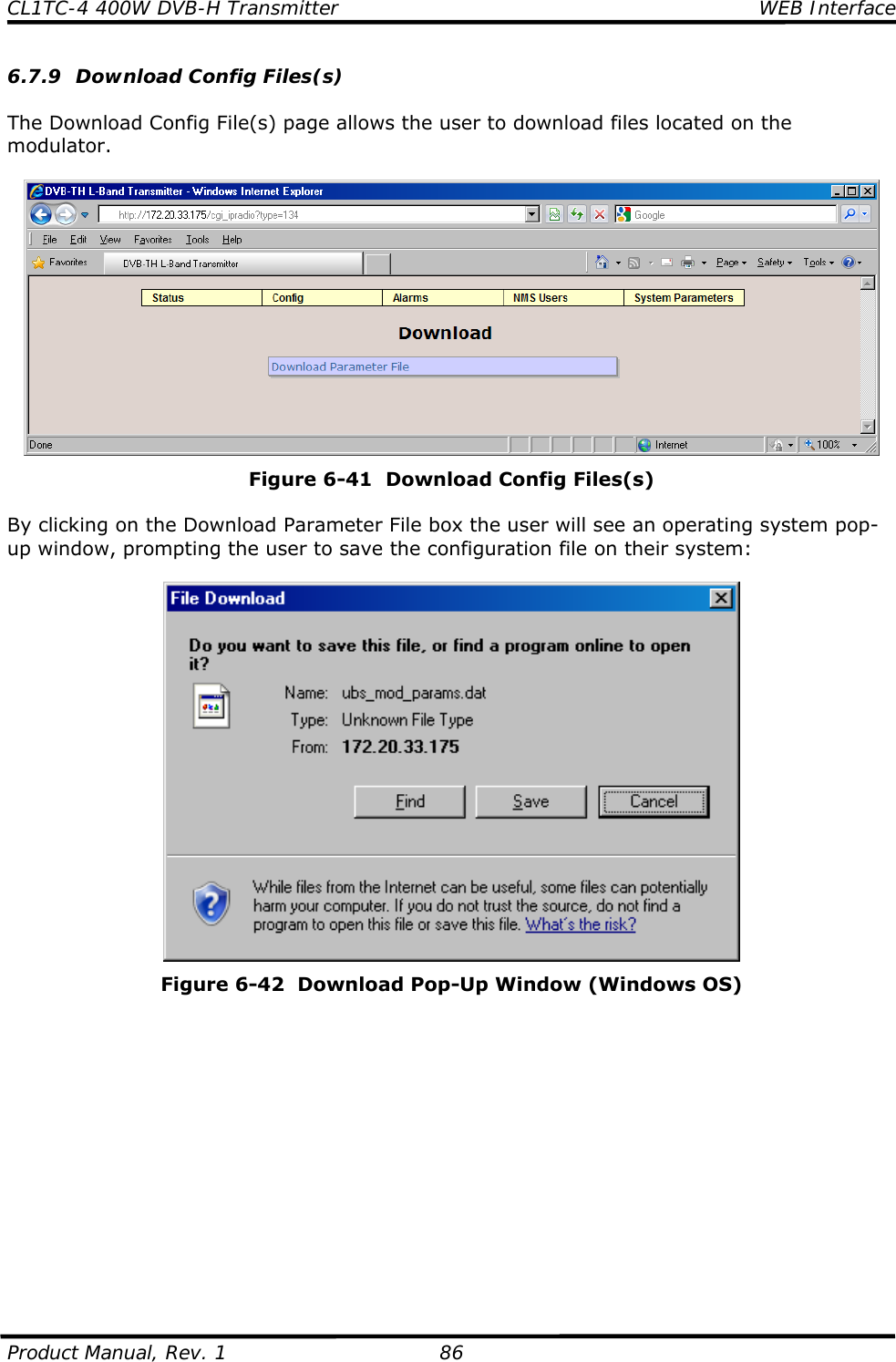

![CL1TC-4 400W DVB-H Transmitter Modulator Front Panel Product Manual, Rev. 1 104 The “current” menu item is always shown in capitalized format with “< >” brackets. If there are more menu items than the LCD can display, three (3) dots are shown in the lower right position – see Example A. Example A ---------------------------------------- DVB-TH L-Band TX <CONFIG> Alarms NMS Users System Pa... ---------------------------------------- If the user presses the 8 button, the display will shift to the left and the next menu item will be selected – see Example B. Example B ---------------------------------------- DVB-TH L-Band TX <ALARMS> NMS Users System Parameters... ---------------------------------------- If the user presses the 6 button in Example A, the highlighted menu item will be selected and the user will enter the sub-menu – see Example C. The character string “DVB-TH L-Band TX” is always positioned in the top left corner of the display, followed by the menu name. The available menu items are shown on the second line and may be selected using the 3 and 8 buttons. The “current” menu item is always shown in capitalized format with “< >” brackets. If there are more menu options than the LCD can display, three (3) dots are shown in the lower right position. Example C ---------------------------------------- DVB-TH L-Band TX, Config <MODULATOR MODE> Transmission Input ... ---------------------------------------- The lowest level of any particular “branch” produces a window that displays the available parameter list; the selected value is shown in square brackets – see Example D. The parameter name is shown in the top left corner of the display, followed by the “current” value. The available menu items are shown on the second line and may be selected using the 3 and 8 buttons. The “current” menu item is always shown in capitalized format with “[ ]” brackets. Example D ---------------------------------------- Spectrum Inversion = OFF [OFF] ON ---------------------------------------- If an alpha numeric parameter is selected, the first digit of the “current” parameter flashes and a cursor shows the position of the digit which can be edited (in this case, “a” from “admin”) – see Example E.](https://usermanual.wiki/UBS-Axcera/CL1TC-4.User-Manual-Part-2/User-Guide-2076418-Page-33.png)
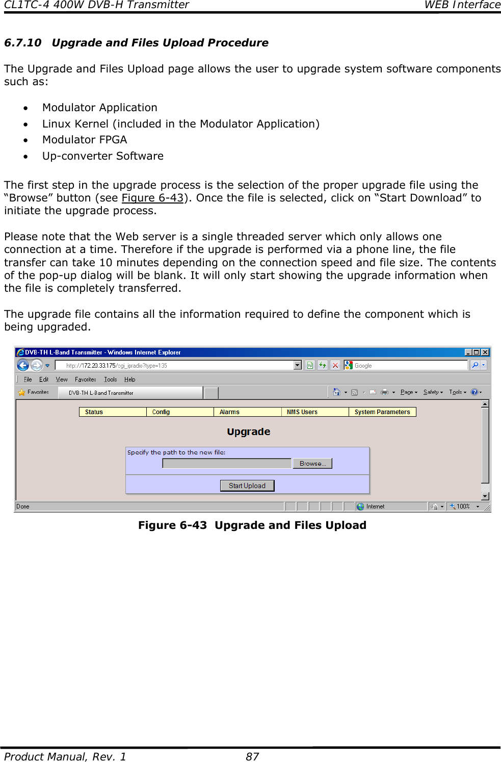
![CL1TC-4 400W DVB-H Transmitter Modulator Front Panel Product Manual, Rev. 1 105 Example E ---------------------------------------- Web Password = admin admin ---------------------------------------- 8.2.2 Configuring Parameters 8.2.2.1 Selection of Enumerated Values ---------------------------------------- Modulator Mode = Normal [Normal] CW Test 1(Carriers Removal... ---------------------------------------- (the square brackets flash at approx. 2 Hz) The current value is shown as the first item in the list, in square brackets. Navigating: w Scrolls the previous item into the “current position”. 8 Scrolls the next item into the “current position”. 6 No effect. 5 Aborts editing and returns to the previous menu level. <EXECUTE> Saves the “current” item as the active parameter and returns to the previous menu level. 8.2.2.2 Editing a Numeric Value ---------------------------------------- RF Output Frequency = 1670000000 1670000000 [167000000..1675000000] ---------------------------------------- (the character 0 alternates between ‘0’ and ‘_’ at approximately 2 Hz) The configurable value that appears on the display is always the current value and the cursor is initially positioned on the last digit. The valid range is displayed in square brackets on the right hand side of the bottom line. Navigating: w Positions the cursor on the previous character or moves to the last character when the cursor is on the first character. 8 Positions the cursor on the next character or moves to the first character when the cursor is on the last character. 6 Decrements the value of the highlighted character. If the character value is ‘0’, the button will change the value to ‘9’. If the parameter can be set to a negative number, the button will toggle between a negative sign (-) and a blank (positive) when the first character is highlighted. 5 Increments the value of the highlighted character. If the character value is ‘9’, the 5 button will change the value to ‘0’. If the parameter can be set to a negative number, the 5 button will toggle between a negative sign (-) and a blank (positive) when the first character is highlighted.](https://usermanual.wiki/UBS-Axcera/CL1TC-4.User-Manual-Part-2/User-Guide-2076418-Page-34.png)
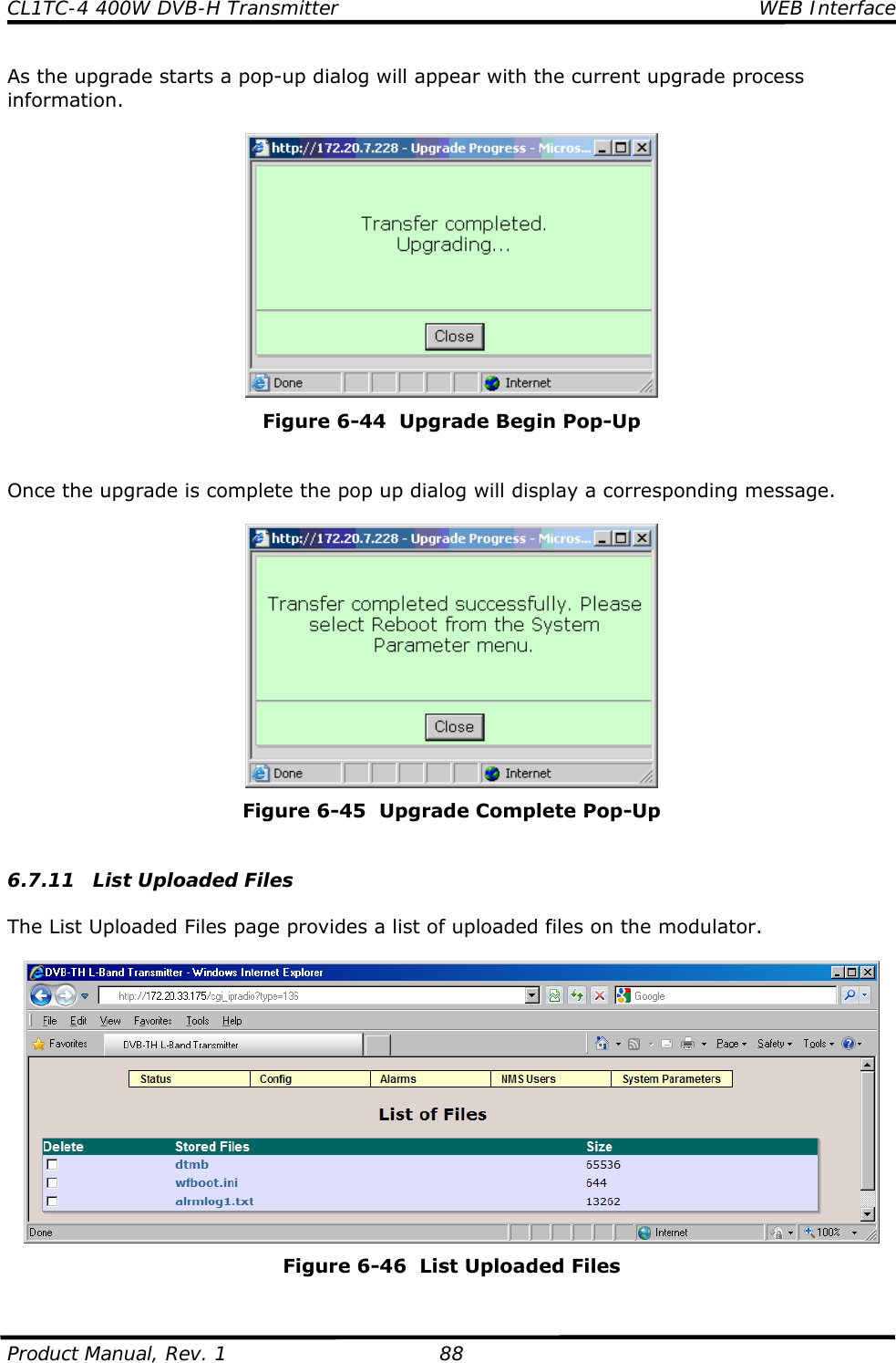
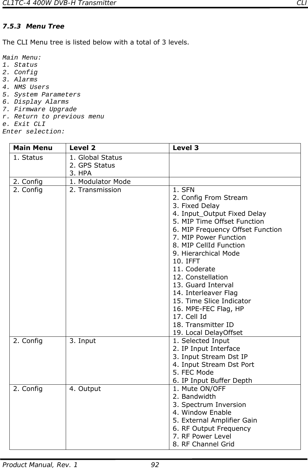
![CL1TC-4 400W DVB-H Transmitter Modulator Front Panel Product Manual, Rev. 1 109 The start point in the Config Menu is: ---------------------------------------- DVB-TH L-Band TX <CONFIG> Alarms NMS Users System Pa... ---------------------------------------- The full list of the level 1 menu items are: • Config • Alarms • NMS Users • System Parameters There are a total of 3 menu levels in the Config Menu chain. Use the left e and right f buttons to navigate between different sub-menu items. Use the down d button to enter a sub-menu or the up c button to return to a higher level. 8.6 Config Menu Tree The Config Menu tree is listed below. There are a total of 3 levels. In some cases there is a shortcut to reach a specific menu directly from a specific Status Display by pressing the EXECUTE button. The place where such a shortcut exists is denoted by a bracketed letter (e.g., [f]) to represent the Status Display where the shortcut exists. Note that the Config x Transmission menu has three possible structures. This reflects the fact that the menu is different whether the transmitter is operating in MFN mode, SFN mode or SFN mode with Config From Stream On. Level 1 Level 2 Level 3 Config Modulator Mode Operating Mode Config Transmission [a] MFN Mode •SFN •Config From Stream •Fixed Delay •Input_Output Fixed Delay •Hierarchical Mode •IFFT •Coderate •Constellation •Guard Interval •Interleaver Flag •Time Slice Indicator, HP •MPE-FEC Flag, HP •Cell Id SFN Mode •SFN •Config From Stream •Fixed Delay •Input_Output Fixed Delay •Hierarchical Mode •IFFT •Coderate](https://usermanual.wiki/UBS-Axcera/CL1TC-4.User-Manual-Part-2/User-Guide-2076418-Page-38.png)
![CL1TC-4 400W DVB-H Transmitter Modulator Front Panel Product Manual, Rev. 1 110 Level 1 Level 2 Level 3 •Constellation •Guard Interval •Interleaver Flag •Time Slice Indicator, HP •MPE-FEC Flag, HP •Cell Id •Transmitter ID •Local DelayOffset SFN Mode (Config From Stream On) •SFN •Config From Stream •Fixed Delay •Input_Output Fixed Delay •MIP Time Offset Function •MIP Frequency Offset Function •MIP Power Function •MIP CellId Function •Hierarchical Mode •Cell Id •Transmitter ID •Local DelayOffset Config Input [b] •Selected Input •IP Input Interface •Input Stream Dst IP •Input Stream Dst Port •FEC Mode •IP Input Buffer Depth Config Output [c] MFN Mode •Mute ON/OFF •Bandwidth •Spectrum Inversion •Window Enable •External Amplifier Gain •RF Output Frequency •RF Power Level •RF Channel Grid •Base Frequency •Base Channel SFN Mode (Config From Stream On) •Mute ON/OFF •Spectrum Inversion •Window Enable •External Amplifier Gain •RF Output Frequency •RF Power Level •RF Channel Grid •Base Frequency •Base Channel](https://usermanual.wiki/UBS-Axcera/CL1TC-4.User-Manual-Part-2/User-Guide-2076418-Page-39.png)
![CL1TC-4 400W DVB-H Transmitter Modulator Front Panel Product Manual, Rev. 1 111 Level 1 Level 2 Level 3 Config RF Channels •RF Freq Channel Config User RF Channels •User Frequency Channel Config Non-Linear Precorrector •NLP State •NLP Profile Config Linear Precorrector •LP State •LP Profile Config HPA Control •RF Output Power Level •Transmitter Operating Mode Config GPS •Max GPS Holdover Time, min •Update System Clock From GPS •System Timezone Config Site •System Description •Contact Information •System Location •Site Address Line 1 •Site Address Line 2 •Site Address Line 3 •Site Address Line 4 •Site Notes Alarms Alarm Properties •Alarm Index •Alarm Enabled •Trap Notification on Alarm •Integration Time •Mute on Alarm •Relay on Alarm •Second Relay on Alarm •Alarm Severity Level Alarms External Voltage Alarm Setting •Voltage1 Trigger Polarity •Voltage1 Trigger Threshold •Voltage2 Trigger Polarity •Voltage2 Trigger Threshold •Voltage3 Trigger Polarity •Voltage3 Trigger Threshold •Voltage4 Trigger Polarity •Voltage4 Trigger Threshold •Voltage5 Trigger Polarity •Voltage5 Trigger Threshold •Voltage6 Trigger Polarity •Voltage6 Trigger Threshold •Voltage7 Trigger Polarity •Voltage7 Trigger Threshold •Voltage8 Trigger Polarity •Voltage8 Trigger Threshold Alarms Log Management [e] •Clear Alarm Log •Logs Display in Reverse •Log To Display NMS Users User Properties •User Index •Username •Authorization Type •Auth. Password •Priv Type •Priv. Password](https://usermanual.wiki/UBS-Axcera/CL1TC-4.User-Manual-Part-2/User-Guide-2076418-Page-40.png)
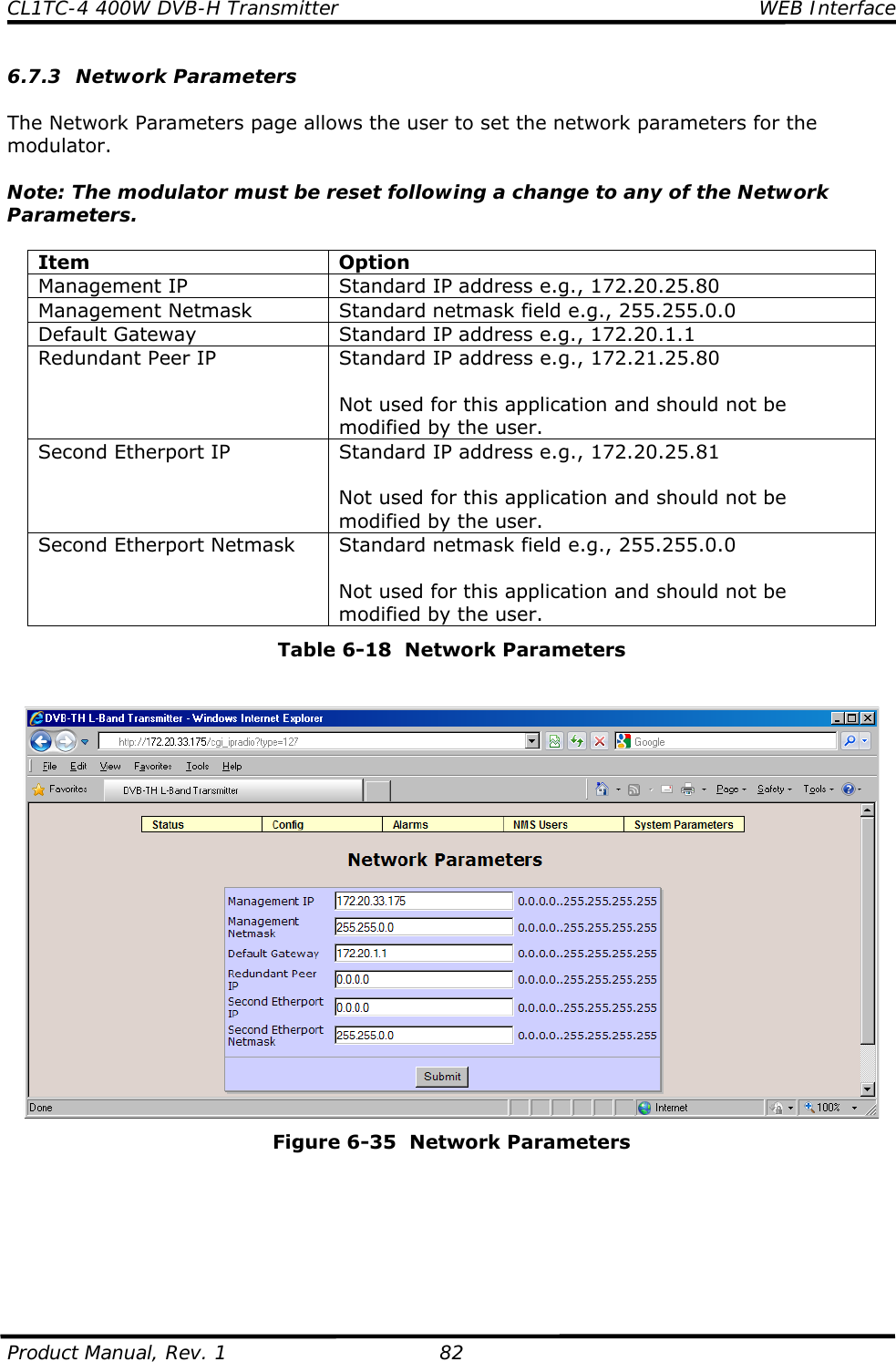
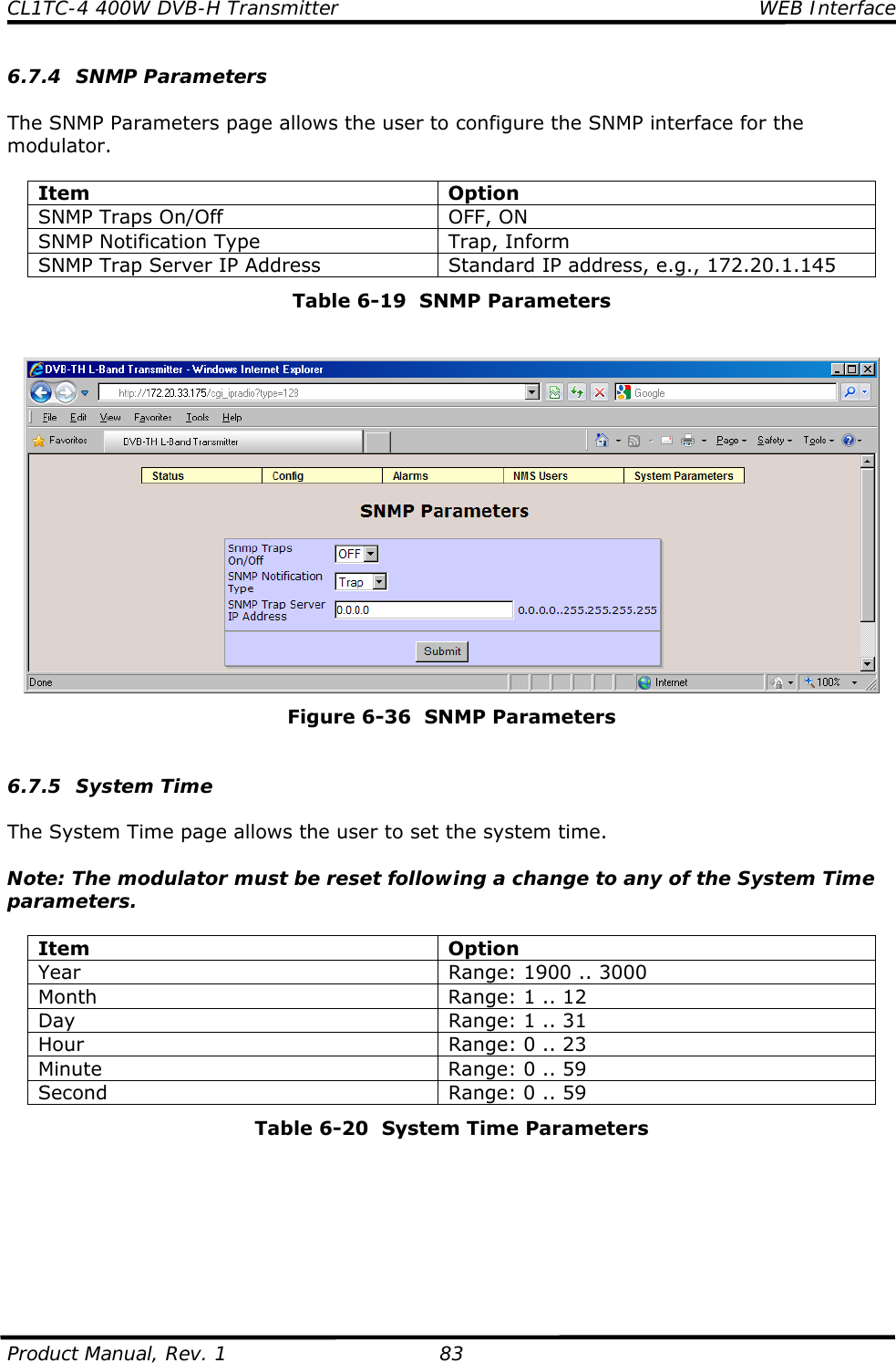
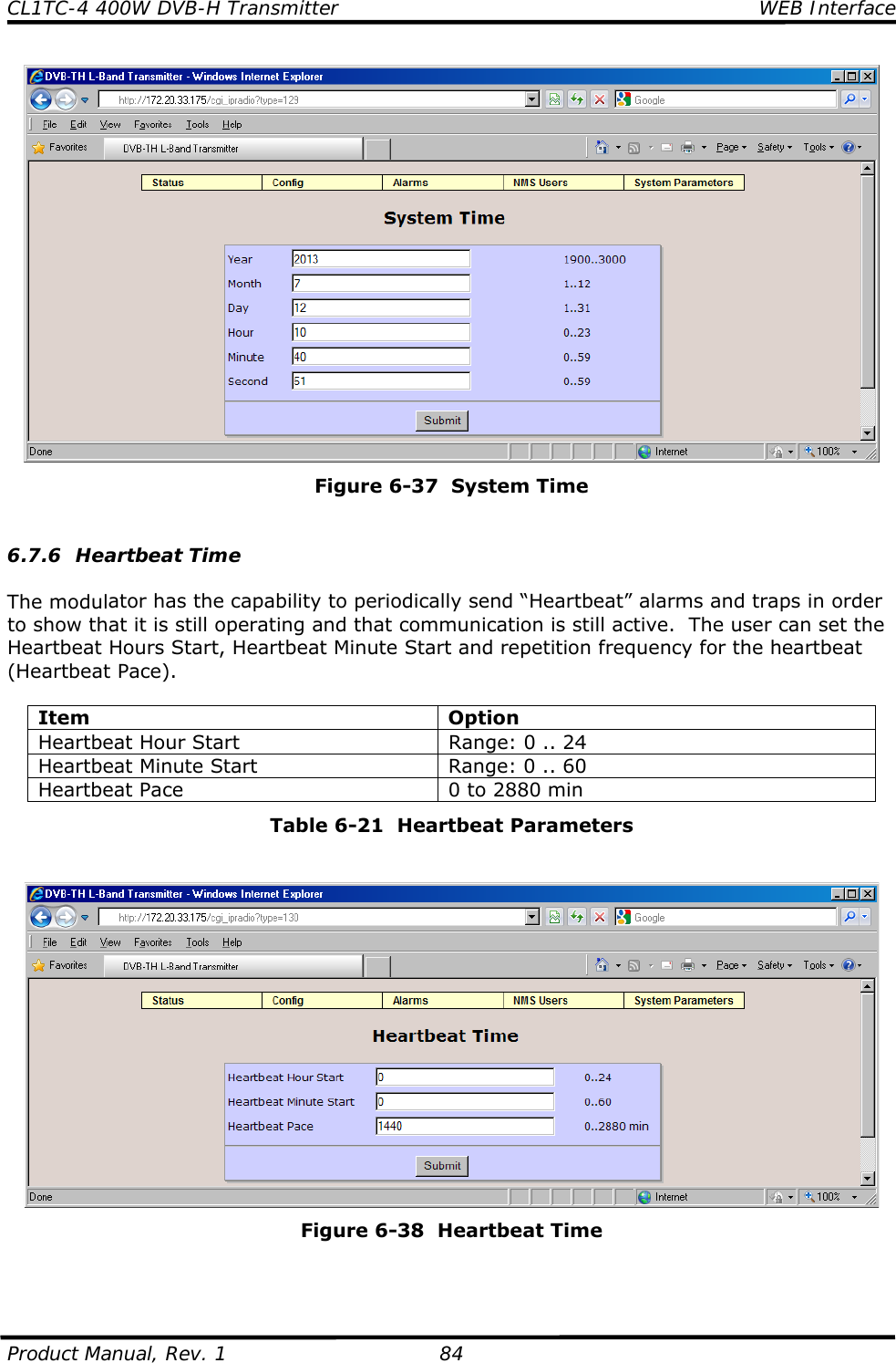
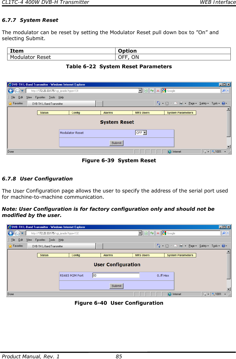
![CL1TC-4 400W DVB-H Transmitter Modulator Front Panel Product Manual, Rev. 1 112 Level 1 Level 2 Level 3 System Parameters Identification •Site Name •Site ID System Parameters Access Control •Web Password System Parameters Network Parameters [f] •Management IP •Management Netmask •Default Gateway •Redundant Peer IP •Second Etherport IP •Second Etherport Netmask System Parameters SNMP Parameters •SNMP Traps On/Off •SNMP Notification Type •SNMP Trap Server IP Address System Parameters System Time •Year •Month •Day •Hour •Minute •Second System Parameters Heartbeat Time •Heartbeat Hour Start •Heartbeat Minute Start •Heartbeat Pace System Parameters System Reset •Modulator Reset System Parameters User Configuration •RS485 M2M Port Table 8-1 Front Panel Menu Tree 8.7 Config ---------------------------------------- DVB-TH L-Band TX, Config <MODULATOR MODE> Transmission Input ... ---------------------------------------- The additional menu items for this sub-menu are: • Modulator Mode • Transmission • Input • Output • RF Channel • User RF Channels • Non-Linear Precorrector • Linear Precorrector • HPA Control • GPS • Site](https://usermanual.wiki/UBS-Axcera/CL1TC-4.User-Manual-Part-2/User-Guide-2076418-Page-41.png)
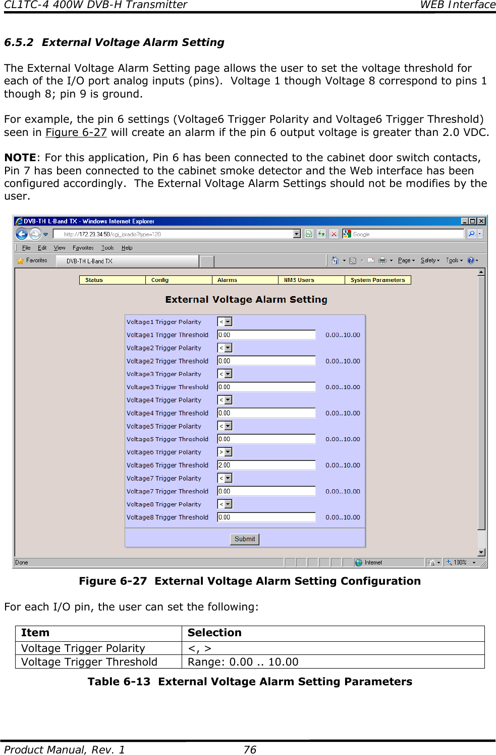
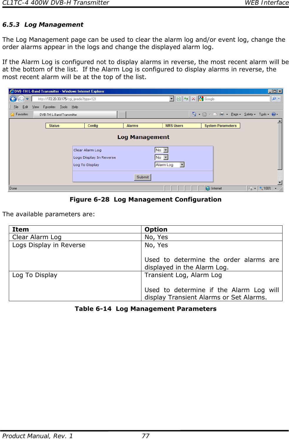
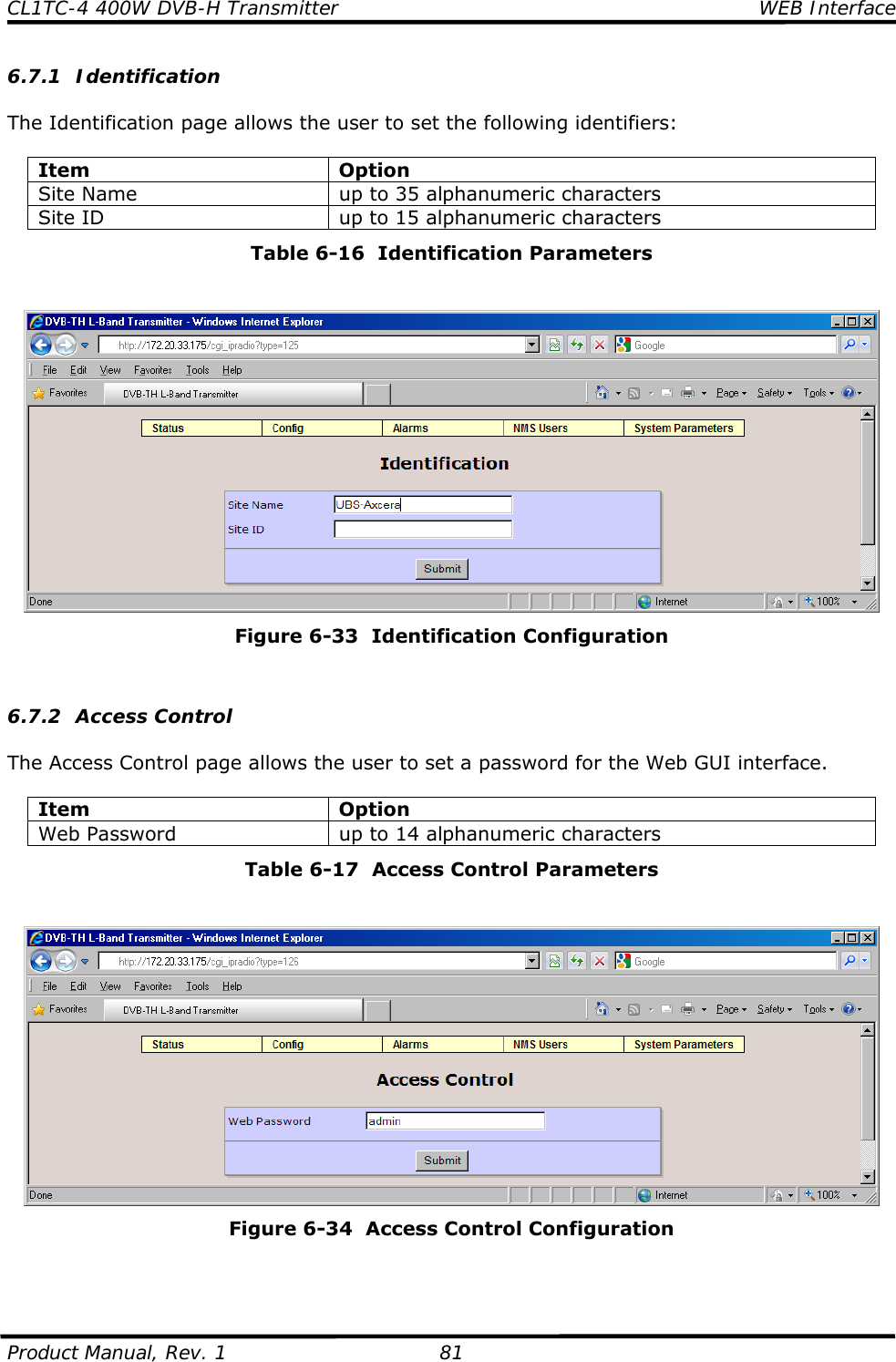
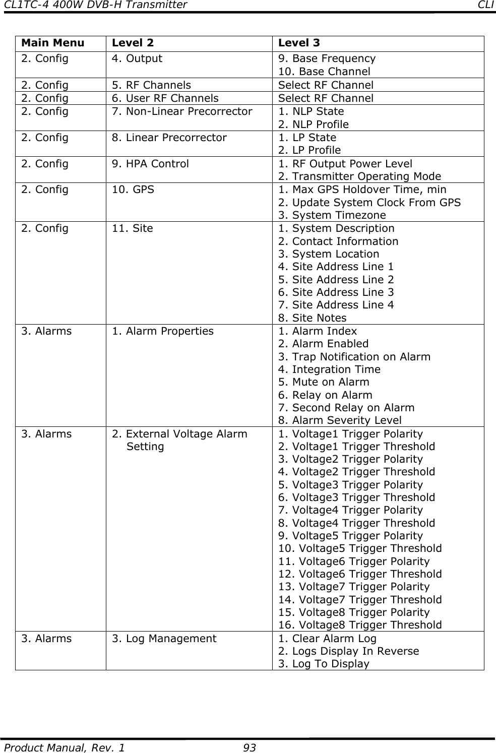
![CL1TC-4 400W DVB-H Transmitter Modulator Front Panel Product Manual, Rev. 1 119 To select a specific alarm to set its properties in other menus the user must first set the Alarm Index value in the Alarm Index sub-menu screen. Upon entering the Alarm Index menu the user will see: ---------------------------------------- Alarm Index = 0 [ Modulator Restarted] Heartbeat ... ---------------------------------------- The Alarm Index menu lists all 66 alarms available in the system, with index values from 0 to 65. The full list of alarms available can be found in Table 10-1. To select a specific alarm to set its properties, scroll through this list using the left e and right f button until the desired alarm is enclosed in square brackets and press EXECUTE. The Alarm Index value will be updated to match this alarm. For example, Modulator Restarted is Alarm Index 0, Heartbeat is Alarm Index 1, and so on. In the other menus the name of the alarm being configured will be displayed. For example, if Heartbeat is selected and the user navigates to the Alarm Severity Level menu the following will be displayed: ---------------------------------------- Heartbeat Alarm Severity Level = Inform [Informative] Critical Warning ---------------------------------------- 8.8.2 Config xExternal Voltage Alarm Setting ---------------------------------------- Alarms, External Voltage Alarm Setting <VOLTAGE1 TRIGGER POLARITY> Voltage1 ... ---------------------------------------- For Voltage1 through Voltage8 the user can set the following: Item Selection Voltage Trigger Polarity <, > Voltage Trigger Threshold Range: 0.00 .. 10.00 8.8.3 Alarms x Log Management ---------------------------------------- Alarms, Log Management <CLEAR ALARM LOG> Logs Display In Rev... ---------------------------------------- Shortcut: To directly reach this menu Press EXECUTE from Status Display e. The options are: Item Option Clear Alarm Log No, Yes Logs Display in Reverse No, Yes Log To Display Transient Log, Alarm Log](https://usermanual.wiki/UBS-Axcera/CL1TC-4.User-Manual-Part-2/User-Guide-2076418-Page-48.png)