UBS Axcera LL50ATC 50-Watt, 1.6 GHz DVB-H Transmitter User Manual rev 3 11
UBS-Axcera 50-Watt, 1.6 GHz DVB-H Transmitter rev 3 11
Contents
- 1. Pro Televsion Modulator Manual
- 2. LL50ATC User Manual
Pro Televsion Modulator Manual

ProTelevision Technologies A/S
Marielundvej 16
DK-2730 Herlev
Denmark
PT 5780
DVB-T Modulator (ASIC)
Instruction Manual

Trade Mark of the DVB Digital Video Broadcasting Project
PROTELEVISION technologies
An ISO 9001 Certified Company
PT 5780 DVB-T Modulator, Instruction Manual: Total number of pages: 95
Copyright 2003 ProTelevision Technologies A/S, Denmark
All Rights Reserved
Printed in Denmark 2003-08-25
Revision: 3.11
Publication number: 9499 493 12611

PT 5780 DVB-T Modulator ProTelevision Technologies Contents
Instruction Manual Revision 3.11
i
Contents
1 SAFETY.................................................................................................................. 1-1
1.1 INTRODUCTION........................................................................................................1-1
1.2 SAFETY PRECAUTIONS .............................................................................................1-1
1.3 CAUTION AND WARNING STATEMENTS ........................................................................1-1
1.4 IMPAIRED SAFETY PROTECTION .................................................................................1-2
1.4.1 Technical Specifications ..............................................................................1-2
1.4.2 Equipment Ratings ......................................................................................1-3
1.5 ELECTROSTATIC SENSITIVE DEVICES ..........................................................................1-3
1.6 SYMBOLS ...............................................................................................................1-4
2 INTRODUCTION AND APPLICATIONS........................................................... 2-1
2.1 APPLICATIONS .........................................................................................................2-1
2.1.1 Block Diagram (PT 5780 features)................................................................2-3
2.2 TRANSMISSION MODES SUPPORTED ...........................................................................2-3
2.3 TRANSPORT STREAM INPUTS.....................................................................................2-4
2.4 ALARM CIRCUITS .....................................................................................................2-6
2.5 OPERATION ............................................................................................................2-6
2.6 FREQUENCY REFERENCES ........................................................................................2-6
2.7 TEST FACILITIES ......................................................................................................2-7
3 INSTALLATION..................................................................................................... 3-1
3.1 INITIAL INSPECTION..................................................................................................3-1
3.2 SAFETY INSTRUCTION ..............................................................................................3-1
3.2.1 Earthing......................................................................................................3-1
3.3 MAINS VOLTAGE CORD AND FUSES ............................................................................3-1
3.4 RACK MOUNTING.....................................................................................................3-2
3.5 CLEANING ..............................................................................................................3-2
3.6 CONFIGURATION......................................................................................................3-3
3.6.1 Wiring schemes for RS 232 (handshake not implemented) ............................3-3
3.6.2 Alarms........................................................................................................3-3
3.6.3 Mute...........................................................................................................3-4
3.6.4 Reset .........................................................................................................3-4
3.7 ACCESS TO AND REPLACEMENT OF PARTS ..................................................................3-4
3.7.1 Safety.........................................................................................................3-4
3.7.2 Access to the Units......................................................................................3-4
4 OPERATING INSTRUCTIONS........................................................................... 4-1
4.1 FRONT PANEL .........................................................................................................4-1
4.1.1 Front Panel Indicators..................................................................................4-1
4.1.2 Front Panel Controls (The menu system)......................................................4-1
4.1.3 Front Panel Display .....................................................................................4-3
4.2 REAR PANEL ...........................................................................................................4-3
4.2.1 Rear Panel Connections ..............................................................................4-3
4.3 MENU SYSTEM – DESCRIPTION AND OPERATION ..........................................................4-5
4.3.1 Power Up ...................................................................................................4-5
4.3.2 Operating Menu System Chart .....................................................................4-6
4.3.3 Status Menu System ...................................................................................4-6
4.3.3.1 Description of Status Display Windows...........................................4-7

PT 5780 DVB-T Modulator ProTelevision Technologies Contents
Instruction Manual Revision 3.11 ii
4.3.4 Configuration Menu System.......................................................................4-11
4.3.4.1 Top-level configuration menu access............................................4-12
4.3.4.2 Context sensitive menu access....................................................4-13
4.3.4.3 TRANSMISSION Menu System (Menu ID 1000) ...........................4-14
4.3.4.4 SIGNAL Menu System (Menu ID 2000)........................................4-15
4.3.4.5 ALARM Menu System (Menu ID 3000).........................................4-18
4.3.4.6 PRESET Menu System (Menu ID 4000) .......................................4-22
4.3.4.7 CONFIGURE Menu System (Menu ID 5000) ................................4-22
4.3.4.8 TEST SIGNAL Menu System (Menu ID 6000)...............................4-24
4.3.4.9 RECEPTION Menu System (Menu ID 7000) .................................4-25
4.3.4.10 EVENT LOG Menu System (Menu ID 8000) .................................4-27
4.3.5 Configuring Parameters .............................................................................4-27
4.3.5.1 Selection from Enumerated Values ..............................................4-27
4.3.5.2 Editing of Numerical Values .........................................................4-28
4.3.5.3 Editing of Text.............................................................................4-29
4.3.5.4 Editing of Percentage Values .......................................................4-30
4.4 FACTORY RESET ...................................................................................................4-30
4.5 SFN MODE OF OPERATION .....................................................................................4-31
4.6 FATAL ALARMS......................................................................................................4-32
4.6.1 Modulator Board Controller Not Responding...............................................4-32
4.6.2 Instrument Too Hot....................................................................................4-32
4.7 ERROR HANDLING AND CODES ................................................................................4-32
5 REMOTE INTERFACE......................................................................................... 5-1
5.1 GENERAL DESCRIPTION............................................................................................5-1
5.2 GENERAL DESCRIPTION OF THE INTERFACE SYNTAX .....................................................5-1
5.2.1 General Information.....................................................................................5-1
5.2.2 Syntax of Program Messages ......................................................................5-2
5.2.3 Syntax of Response Messages ....................................................................5-2
5.2.4 Long and Short Form...................................................................................5-3
5.2.5 Syntax Elements.........................................................................................5-3
6 RS232 COMMUNICATION.................................................................................. 6-1
6.1 REFERENCES ..........................................................................................................6-1
6.2 COMMANDS EXPLANATION ........................................................................................6-1
6.2.1 Mandated Commands .................................................................................6-1
6.2.2 Required Commands...................................................................................6-2
6.2.2.1 SYSTem commands .....................................................................6-2
6.2.2.2 STATus commands.......................................................................6-2
6.2.3 Instrument Commands ................................................................................6-3
6.2.3.1 DIAGnostic commands..................................................................6-3
6.2.3.2 SYSTem commands .....................................................................6-3
6.2.3.3 USER commands .........................................................................6-5
6.2.3.4 DISPlay commands.......................................................................6-6
6.2.3.5 INPut commands ..........................................................................6-6
6.2.3.6 OUTPut commands.......................................................................6-8
6.2.3.7 MONitor command......................................................................6-13
6.2.3.8 PRECorrect (Nonlinear Pre-corrector) commands .........................6-13
6.2.3.9 LPRecorrect (Linear Pre-corrector) commands .............................6-17
6.2.3.10 SFN commands ..........................................................................6-18
6.2.3.11 ALARM commands .....................................................................6-20
6.2.3.12 EVENT commands......................................................................6-23

PT 5780 DVB-T Modulator ProTelevision Technologies Contents
Instruction Manual Revision 3.11
iii
6.2.3.13 TEST commands ........................................................................6-23
6.2.3.14 FACTORY commands.................................................................6-24
6.3 COMMANDS SUMMARY ...........................................................................................6-25
6.3.1 Mandated Commands ...............................................................................6-25
6.3.2 Required commands .................................................................................6-25
6.3.2.1 SYSTem subsystem....................................................................6-25
6.3.2.2 STATus subsystem.....................................................................6-25
6.3.3 Instrument commands ...............................................................................6-26
6.3.3.1 DIAGnostic subsystem................................................................6-26
6.3.3.2 SYSTem subsystem....................................................................6-26
6.3.3.3 USER subsystem........................................................................6-26
6.3.3.4 DISPlay subsystem.....................................................................6-26
6.3.3.5 INPut subsystem.........................................................................6-27
6.3.3.6 OUTPut subsystem.....................................................................6-27
6.3.3.7 MONitor subsystem.....................................................................6-29
6.3.3.8 PRECorrect (Nonlinear Pre-corrector) subsystem .........................6-29
6.3.3.9 LPRecorrect (Linear Pre-corrector) subsystem..............................6-29
6.3.3.10 SFN subsystem ..........................................................................6-30
6.3.3.11 ALARm subsystem......................................................................6-30
6.3.3.12 EVENt subsystem.......................................................................6-31
6.3.3.13 TEST subsystem ........................................................................6-31
6.3.3.14 FACTory subsystem....................................................................6-31
6.4 ERROR CODES ......................................................................................................6-32
6.4.1 Command errors [-199, -100] .....................................................................6-32
6.4.2 Execution errors [-299, -200] ......................................................................6-33
6.4.3 Device specific errors [-399, -300] ..............................................................6-34
6.4.4 Query errors [-499, -400] ...........................................................................6-34
6.4.5 Device specific errors [1, 32468] ................................................................6-34
APPENDIX A…...........................................................................................….A-1
APPENDIX B………………………………………………………………………..A-2

PT 5780 DVB-T Modulator ProTelevision Technologies Contents
Instruction Manual Revision 3.11 iv
This page is intentionally left blank

PT 5780 DVB-T Modulator ProTelevision Technologies Safety
Instruction Manual Revision 3.11
1-1
1 Safety
Read this chapter carefully before installation and use of the instrument.
1.1 Introduction
The instrument described in this manual has been designed for use by properly trained
personnel only.
Adjustment, maintenance and repair of the exposed equipment should only be carried out by
qualified personnel who are aware of hazards involved.
1.2 Safety Precautions
For the correct and safe use of the instrument, it is essential that both operating and servicing
personnel follow generally accepted safety procedures in addition to the safety precautions
specified in this manual. Specific warning and caution statements, where applicable, are found
throughout this manual. Note that warning and caution statements and/or symbols are marked
on the instrument as well.
This manual provides technical information important for safe operation of the equipment.
Please refer to the relevant sections of the manual for technical specifications, installation and
operating instructions.
Special attention must be paid to the following issues:
♦ Protective earthing of the instrument is required for the accessible terminals to be safe.
(IEC 1010-1 Safety class I instrument)
♦ The actual environmental conditions must be checked against the specification
♦ Mains voltage must be inside the specified range
The opening of covers or removal of parts, except those to which access can be gained by
hand, is liable to expose live parts and terminals.
If adjustment, maintenance, or repair of the opened instrument is unavoidable, it must only be
carried out by a skilled person who is aware of the hazards involved.
1.3 Caution and Warning Statements
Caution
Used to indicate correct operation or maintenance in order to prevent damage to, or destruction
of equipment or other property.
Warning
Used to indicate a potential hazard that requires correct procedures or practices in order to
prevent personal injury.

Safety ProTelevision Technologies PT 5780 DVB-T Modulator
Instruction Manual Revision 3.11 1-2
1.4 Impaired Safety Protection
1.4.1 Technical Specifications
This manual provides technical information important for safe operation of the equipment.
Please refer to the Chapter Product Data for information regarding technical specifications and
the Chapter Installation and Operating Instructions regarding instructions for use.
Technical assistance may be obtained from your local ProTelevision Technologies customer
support organization or from:
ProTelevision Technologies
Marielundvej 16
DK-2730 Skovlunde
Denmark
Phone : +45 4470 0000
Fax : +45 4470 0001
E-Mail : helpdesk@protelevision.com
Website : http://www.protelevision.com

PT 5780 DVB-T Modulator ProTelevision Technologies Safety
Instruction Manual Revision 3.11
1-3
1.4.2 Equipment Ratings
The instrument can be used with a mains voltage supply of:
Voltage range:
90 – 132VAC / 180 - 250 V AC
Frequency:
47 - 63 Hz
The power consumption:
Does not exceed 50 VA
The instrument is designed for the following environmental conditions:
♦ Indoor use
♦ Altitudes up to 2000 m
♦ Temperatures between 5oC and 40oC
Maximum relative humidity of 80% for temperatures up to 31oC, decreasing linearly to 50%
relative humidity at 40oC.
The instrument is equipped with a number of input and output terminals as described in the
Chapter Product Data.
The terminals are protected from becoming hazardous live by means of basic insulation and
protective screening.
Whenever it is likely that safe operation is impaired, the instrument must be made inoperative
and secured against unintended operation. The appropriate servicing authority must be
informed.
For example, safety is likely to be impaired if the instrument fails to perform the intended
measurements or shows visible damage.
WARNING: Protection provided by the equipment may be impaired, if the equipment is used in
a manner not specified by this manual.
ATTENTION
1.5 Electrostatic Sensitive Devices
All ICs and many other semi-conductors are susceptible to electrostatic discharges ESD).
Careless handling during repair can reduce lifetime drastically.
When repairing, make sure that you are connected to the same potential as the mass of the set
via a wrist wrap with resistance. Keep components and tools also at this potential.
Safety ProTelevision Technologies PT 5780 DVB-T Modulator
Instruction Manual Revision 3.11 1-4
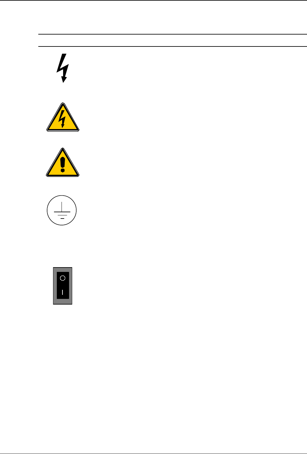
1.6 Symbols
Symbol Colour: Explanation:
Red
High voltage terminal: a terminal at which a voltage, with
respect to another terminal or parts exists or may be
adjusted to 1000 V or more. (High voltage > 1000 V).
Black/Yellow
Live part shock risk of electric shock.
Black/Yellow
To preserve the instrument from damage the operator
must refer to an explanation in the instruction manual.
White/Black
Protective earth (grounding) terminal.
~
Black
Alternating current (placed on the identification plate).
White/Black
Off (supply - mains switch).
On (supply - mains switch).

PT 5780 DVB-T Modulator ProTelevision Technologies Introduction and Applications
Instruction Manual Revision 3.11
2-1
2 Introduction and Applications
Designed to meet the most demanding requirements of today’s Digital Terrestrial Television
Broadcast Market, the DVB-T Modulator PT 5780 from ProTelevision Technologies is ranked
number one in its class. A key factor in the products success is the quality of the coding and
modulation process. The unit is furthermore highly flexible and therefore easily tailored to
provide the exact features required in a specific application. This means that you will only have
to pay for the functional features that you need. Retrofitting of features is easy. Normally, the
retrofitting only involves uploading new firmware and software by means of a standard PC.
.
2.1 Applications
The performance and flexibility of the PT 5780 allows it to excel in any application related to
DVB-T modulation. Being a DVB-T modulator the core function of the PT 5780 is to modulate
an MPEG-2 transport stream (input) onto a DVB-T compliant COFDM spectrum (output) in
accordance with the rules for channels coding and modulation specified in the DVB-T standard
ETSI EN 300 744.
Basic version
The basic version of the PT 5780 delivers the COFDM spectrum on a user-defined frequency
between 35 and 37 MHz. The default polarity of the spectrum is ‘Inverted’ as normal for a DVB-
T IF signal. However, the user can freely switch the polarity to ‘non-inverted’ if required. The
spectrum bandwidth may be user configured to 8 or 7MHz as required. This flexibility will allow
the user to interface the IF signal to a wide range of transmitters and frequency converters.
The basic unit has two MPEG-2 inputs (ASI format). Switching between the two inputs can be
done manually and automatically. The latter option provides near seamless switching to a
secondary transport stream in case the primary transport stream source fails (a truly valuable
feature for broadcast applications.)
The user can configure the basic version to any transmission mode listed in ETSI EN 300 744
(excluding hierarchical mode and SFN mode.)
Optional features
A broad range of optional features allows tailoring the modulator for the specific application.
If the output COFDM spectrum is required on a frequency not covered by the basic version (35-
37MHz) the RF Converter option PT 8715 is the answer. This high performance converter
covers the entire frequency range from 30MHz to 1GHz in steps of just 1Hz. The user can freely
set the polarity of the spectrum to inverted or Non-inverted as required. With this converter the
PT 5780 will cover any spectrum application and frequency requirement that you will come
across in the field of DVB-T.
To upgrade the PT 5780 for SFN transmission you will only need to add the SFN option PT
8732. This option provides the PT 5780 with market leading SFN performance with respect to
basic timing accuracy and extent of the local delay offset range. Also, even when the SFN
option is installed you can still select MFN mode via the front panel controls. A convenient
feature when conducting pre-testing and alignment of RF parameters on transmitter installations
before the timing references and transport stream with MIP are in place (as a general rule SFN
modulators must mute the output if either of these signals is absent).

Introduction and Applications ProTelevision Technologies PT 5780 DVB-T Modulator
Instruction Manual Revision 3.11 2-2
To extend the standard range of transmission modes to include support of hierarchical
modulation the Hierarchical Modulation option PT 8733 must be added. Hierarchical
modulation allows simultaneous transmission of two MPEG-2 transport streams. The
compromise between data rate and ruggedness can be set differently between the two virtual
channels. For example:
• a highly protected channel for transmission to mobile and/or portable receivers and
• a high capacity channel, at the expense of ruggedness, for transmission to rooftop
antennas.
Another typical application is simulcasting of the same program in high definition resolution and
standard definition resolution. A significant benefit of hierarchical modulation is that the total
data-rate available in a system with two hierarchically modulated RF channels is higher than
what is available for a two-channel non-hierarchical system where one RF channel is strictly
dedicated to mobile/portable receivers and the other RF channel is strictly dedicated for
transmission to rooftop antennas.
The hierarchical option itself is often supplemented by adding also an extra set of ASI inputs
(dual input option PT 8716) thereby upping the total to four ASI inputs. Access to four ASI
inputs will preserve the possibility also in hierarchical mode to switch almost seamlessly to a
secondary transport stream source in case the primary transport stream source fails (HP
primary input, HP secondary input, LP primary input, LP secondary input).
By adding the 6MHz BW option PT 8735 the PT 5780 will, in addition to the standard 8 and 7
MHz BW, also support transmission in the 6MHz bandwidth mode that is intended for
applications in North and South America, Korea, Japan and elsewhere where 6MHz channel
raster is standard. Including this option for T&M and R&D applications is also highly attractive
as the user simply executes the switching between the three bandwidths via the instrument front
panel (one instrument covers all bandwidths defined by the ETS for DVB-T transmission).
To maximise the performance of the transmitter in which the modulator is installed the Digital
Linear and Non-linear Pre-corrector PT 8731 option is recommended. The Non-linear pre-
corrector balances out gain and phase non-linearity in the transmitter RF power amplifier
thereby reducing significantly the in-band as well as out of band intermodulation generated by
the amplifier. This optimisation of the performance will extend the transmitters coverage area
and ease the performance requirement from the transmitter output filter used for suppressing
the radiation in adjacent channels below the maximum allowed level. The linear pre-corrector
balances out level and group delay variations over the channel bandwidth caused by the
transmitter antenna filter and/or channel combiner filers. The linear optimisation of the signal
radiated from the transmitter means that the channel equalizer of the DVB-T receiver may focus
all its correction capacity on level and group delay errors originating from the actual
transmission path. The characteristics of the linear and non-linear pre-correction curves are set
by means of an easy to use and highly intuitive graphical user interface, the IMD Buster
software package (Windows compatible).
Two options for remote control of the PT 5780 exist. The WebLink option PT 8717 allows
remote control of the PT 5780 via Ethernet (TCP/IP). The system is based on a Web server
mounted inside the PT 5780. The Web pages stored on the Web server are designed as a
complete graphical user interface (GUI) for testing the status and setting the parameters of the
modulator. The WebLink concept is popular because remote control with this system only
requires a standard PC with a network interface card (NIC) and a Web browser (Microsoft
Explorer 5.0). The SNMP client option PT 8727 allows remote control of the PT 5780 in
PT 5780 DVB-T Modulator ProTelevision Technologies Introduction and Applications
Instruction Manual Revision 3.11
2-3
accordance with the SNMP protocol (Get, Set and SNMP traps). This remote control option is
intended for systems solutions where it is desired to integrate the control of a range of (SNMP
compliant) equipment in a common management system, the SNMP manager. The
management system must be adapted/designed to the specific systems requirements and it is
therefore not included with the supplied SNMP client option.
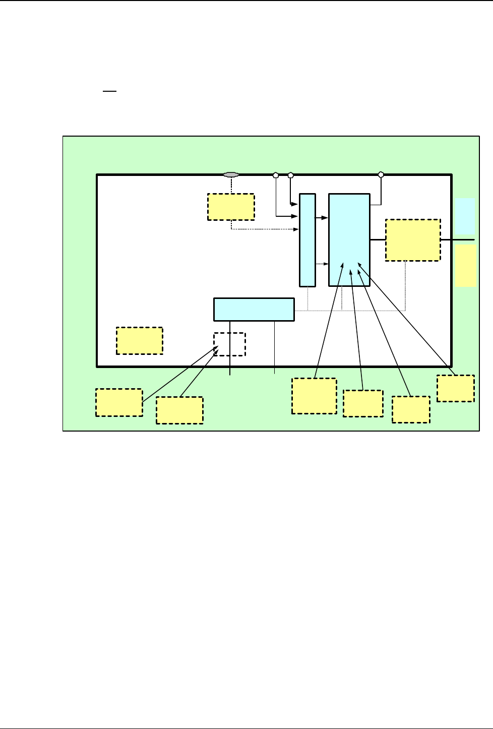
2.1.1 Block Diagram (PT 5780 features)
Rev 3.0 23.01.2003
u/5780/work/hso/manual V3/drawings/5788 block diagram (features).vsd
COFDM
modulator
(8+7MHz BW,
MFN)
OPTION PT 8715
RF converter
(RF
30-
1000
MHz)
ASI input-A
IF monitoring
36 MHz
MPEG-2 TS
DVB-T Modulator
PT 5780
ASI input-B
TS source selector
HP
LP
RS232 for SCPI
control
or
Optionally RJ45
for Ethernet
RS232 for SCPI
control
OPTION PT 8717
WebLink for Web
browser control OPTION PT 8727
SNMP Client
OPTION PT 8731
Digital Linear
and
Non-linear
Pre-correction
System controller
(Local and remote)
OPTION
PT 8732
SFN Support
OPTION
PT 8733
Hierarchical
modulation
OPTION
PT 8735
8-7-6 MHz BW
OPTION PT 8720
Precision TCXO
0.01ppm
IF
35-
37
MHz
OPTION PT 8723
SPI LVDS input
2.2 Transmission Modes Supported
♦ MFN mode and SFN mode (SFN requires option PT 8732)
♦ 6, 7, 8 MHz (6MHz requires option PT 8735)
♦ FFT size: 2k or 8k
♦ Guard Interval: 1/4, 1/8, 1/16, and 1/32
♦ Code Rates: 1/2, 2/3, 3/4, 5/6, and 7/8
♦ Modulation Constellations: QPSK (4 QAM), 16 QAM, and 64 QAM
♦ Hierarchical α 1, 2, 4 (hierarchical mode requires option PT 8733)

Introduction and Applications ProTelevision Technologies PT 5780 DVB-T Modulator
Instruction Manual Revision 3.11 2-4
2.3 Transport Stream Inputs
The standard version of the PT 5780 DVB-T modulator is provided with two serial (ASI) inputs.
By non-hierarchical mode the active input is selected either via the front panel or the remote
control. By hierarchical mode one input is assigned to the high priority stream and the other
input is assigned to the low priority stream. The inputs accept an MPEG transport stream
according to the DVB recommendation. Both 188 and 204 byte transport packets are supported
(in the 204 byte mode the last 16 bytes are always overwritten by the Reed-Solomon
redundancy data generated by the modulator). The available data rate for transmission is stated
in the tables below in accordance with the selected constellation, code rate and guard interval.
Please notice that separate tables applies to 8MHz , 7MHz, and 6MHz bandwidth respectively.
By hierarchical mode 64 QAM constellation and 16QAM constellation can be selected. The
available data rate is divided between the high priority channel and the low priority channel. The
bit rate for the high priority channel is equal to the capacity stated in the QPSK section of the
applicable table irrespective of the constellation chosen. For the low priority channel the
capacity depends on the chosen constellation (64Qam or 16QAM). By 64QAM constellation the
capacity of the hierarchical low priority channel is equal to the capacity stated in the 16QAM
section of the applicable table. By 16QAM constellation the capacity of the hierarchical low
priority channel is equal to the capacity stated in the QPSK section of the applicable table.
In Table 2-1 the maximum useful bit rates are indicated for all valid transmission modes in an
8 MHz system.
Modulation
Code rate
Guard interval
1/4 1/8 1/16 1/32
½ 4,98 5,53 5,85 6,03
2/3 6,64 7,37 7,81 8,04
QPSK ¾ 7,46 8,29 8,78 9,05
5/6 8,29 9,22 9,76 10,05
7/8 8,71 9,68 10,25 10,56
½ 9,95 11,06 11,71 12,06
2/3 13,27 14,75 15,61 16,09
16-QAM ¾ 14,93 16,59 17,56 18,10
5/6 16,59 18,43 19,52 20,11
7/8 17,42 19,35 20,49 21,11
½ 14,93 16,59 17,56 18,10
2/3 19,91 22,12 23,42 24,13
64-QAM ¾ 22,39 24,88 26,35 27,14
5/6 24,88 27,65 29,27 30,16
7/8 26,13 29,03 30,74 31,67
Table 2-1 Available data rate for 8MHz DVB-T

PT 5780 DVB-T Modulator ProTelevision Technologies Introduction and Applications
Instruction Manual Revision 3.11
2-5
In Table 2-2 the maximum useful bit rates are indicated for all valid transmission modes in a
7 MHz system.
In Table 2-3 the maximum useful bit rates are indicated for all valid transmission modes in a
6 MHz system.
With 204 byte packet input the maximum bit rates are increased accordingly.
Modulation
Code rate
Guard interval
1/4 1/8 1/16 1/32
½ 4,354 4,838 5,123 5,278
2/3 5,806 6,451 6,830 7,037
QPSK ¾ 6,532 7,257 7,684 7,917
5/6 7,257 8,064 8,538 8,797
7/8 7,620 8,467 8,965 9,237
½ 8,709 9,676 10,246 10,556
2/3 11,612 12,902 13,661 14,075
16-QAM ¾ 13,063 14,515 15,369 15,834
5/6 14,515 16,127 17,076 17,594
7/8 15,240 16,934 17,930 18,473
½ 13,063 14,515 15,369 15,834
2/3 17,418 19,353 20,491 21,112
64-QAM ¾ 19,595 21,772 23,053 23,751
5/6 21,772 24,191 25,614 26,390
7/8 22,861 25,401 26,895 27,710
Table 2-2 Available data rate for 7MHz DVB-T
Modulation
Code rate
Guard interval
1/4 1/8 1/16 1/32
½ 3,732 4,147 4,391 4,524
2/3 4,976 5,529 5,855 6,032
QPSK ¾ 5,599 6,221 6,587 6,786
5/6 6,221 6,912 7,318 7,540
7/8 6,532 7,257 7,684 7,917
½ 7,465 8,294 8,782 9,048
2/3 9,953 11,059 11,709 12,064
16-QAM ¾ 11,197 12,441 13,173 13,572
5/6 12,441 13,824 14,637 15,080
7/8 13,063 14,515 15,369 15,834
½ 11,197 12,441 13,173 13,572
2/3 14,929 16,588 17,564 18,096
64-QAM ¾ 16,796 18,662 19,760 20,358
5/6 18,662 20,735 21,955 22,620
7/8 19,595 21,772 23,053 23,751
Table 2-3 Available data rate for 6MHz DVB-T

Introduction and Applications ProTelevision Technologies PT 5780 DVB-T Modulator
Instruction Manual Revision 3.11 2-6
With Multi Frequency Network operation (MFN) the built-in Transport Stream Adapter (TSA)
performs the function of discarding any stuffing present on the input stream, inserting new
stuffing (0-packets) to adjust the bit rate and finally recalculating the PCR values of the MPEG2
transport stream. Thus the modulator will accept any transport stream with a useful bit rate
lower than the maximum indicated in the table.
When operating in the single frequency network mode, the bit rate must be exact. The applied
transport stream must furthermore include valid MIP information.
2.4 Alarm Circuits
Two independent alarm circuits are provided. Each circuit may be “armed” for a number of
conditions important for correct operation. Alarm output is via floating contacts on the rear panel
as well as via the remote control. A red LED on the front panel indicates an existing alarm
condition while the display will show the nature of the alarm.
2.5 Operation
The DVB-T Modulator may be configured and operated from either the front panel or via the
remote control port. The front panel control is implemented as a menu system. The status or
configuration menu of interest is displayed on a 2-line LCD display. Navigation between the
menus is done by means of a set of cursor keys (UP, DOWN, LEFT, RIGHT and an EXECUTE
key). To facilitate the remote control of several transmitters each modulator may be individually
named (16 characters). This “name” appears on the front panel display and is available on the
remote port.
Also the modulator may be controlled by data embedded in the incoming MPEG transport
stream itself. If this mode is enabled, it will have highest priority and other controls will be
inhibited. Note this will be the normal mode of operation in a Single Frequency Network (SFN).
When not assisting in configuration or mode selection, the front panel display will show the
status and operational modes of the modulator. In case of an alarm the nature of the cause of
the alarm will be shown.
All settings are always saved in an internal non-volatile storage. This means that the last saved
configuration will automatically be recalled at power on.
2.6 Frequency References
The modulator is equipped with an internal frequency reference with stability of ±
1ppm,adequate for many applications including multi frequency applications. Where higher
accuracies are required, an external 10 MHz frequency reference input is provided.
In Single Frequency Networks (SFN) this input must be connected to an external 10 MHz
reference typically obtained via GPS. In SFN mode the separate 1 pulse per second reference
input must also be connected to the special 1 PPS output of the GPS reference.

PT 5780 DVB-T Modulator ProTelevision Technologies Introduction and Applications
Instruction Manual Revision 3.11
2-7
2.7 Test Facilities
The DVB-T Modulator PT 5780 features a range of useful test signal for both off-line and on-line
testing.
Single carrier:
The single carrier test signal is an off-line test signal (i.e. it interrupts the modulators data
transmission). When the single carrier test signal is activated the normal DVB-T spectrum is
substitutes for a single continuous sine wave located at the centre frequency of the normal in-
service DVB-T spectrum. The RMS level of the sine equals the average RMS level in the full
bandwidth of the normal DVB-T spectrum. The signal is therefore excellent for adjusting
transmitter level and/or verifying frequency accuracy or phase noise performance for the
modulator output.
-1 Carrier test signal
For special tests any single one of the carriers in the DVB-T spectrum can be switched off. This
test signal is in principle an off-line test signal. However, as the FEC of the COFDM coding will
normally cope with the loss of a single carrier without difficulty the signal can be activated during
normal transmission with marginal influence to the performance (slight increase in BER may be
noticed).
-50 Carrier test signal
To allow analysis of in-band intermodulation in a transmitter system 50 consecutive carriers in
the DVB-T spectrum can be switched off. The location of the 50-carrier hole can freely be
selected but typically the hole is placed at the centre of the spectrum. It is recommended to use
this test signal only for off-line tests. However, in most cases the transmission service is
maintained despite the loss of 50 carriers thanks to the FEC of the COFDM coding.
TS Stuffing
This test signal facilitates testing of a transmission systems IF and/or RF parameters even when
no MPEG-2 input is available (MFN mode only). When the TS Stuffing signal is activated a
pseudo random bit sequence as described in section 9.16.1 of the DVB-T Measurement
Guidelines ETR 290 is transmitted.

Introduction and Applications ProTelevision Technologies PT 5780 DVB-T Modulator
Instruction Manual Revision 3.11 2-8
This page is intentionally left blank

PT 5780 DVB-T Modulator ProTelevision Technologies Installation
Instruction Manual Revision 3.11
3-1
3 Installation
3.1 Initial Inspection
Check the contents of the shipment for completeness and possible transport damage. If the
contents are incomplete or damaged, a claim should be filed with the carrier immediately, and
the ProTelevision Help Desk should be notified in order to facilitate the repair or replacement of
the instrument.
3.2 Safety Instruction
3.2.1 Earthing
Before any other connection is made, the instrument must be connected to a protective earth
conductor in one of the following ways: via the three-core mains cable via the protective earth
terminal marked.
Before connecting the equipment to the mains of the building installation, the proper functioning
of the protective earth lead of the building installation needs to be verified.
Warning: Any interruption of the protective conductor inside or outside the instrument, or
disconnection of the protective earth terminal, is likely to make the instrument dangerous.
Intentional interruption is prohibited.
3.3 Mains Voltage Cord and Fuses
Different power cords are available for the various voltage outlets.
Note:
If the mains plug has to be adapted for local use, only a qualified person should carry out this
task.
This instrument is equipped with a tap-less switch mode power supply that covers most nominal
voltage ranges in use: 90-132 VAC RMS / 180-250 VAC RMS. This obviates the need to adapt
to the local mains voltage.
The mains frequency is 48-65 Hz.
Warning: This instrument shall be disconnected from all voltage sources when renewing a fuse.
Mains fuse rating: 2 pcs. 1.25A slow blow, 250 V.
The mains fuse-holder is located on the rear panel of the instrument.
If the mains fuse has to be replaced please proceed as follows:
1. Remove the mains cable.
2. Lift the plastic cover (fuse-holder) by means of a small screwdriver.
3. Insert the new fuse into the top of the fuse-holder.
4. Re-insert the cover (fuse-holder).

Installation ProTelevision Technologies PT 5780 DVB-T Modulator
Instruction Manual Revision 3.11 3-2
Warning: Make sure that only fuses of the required rating, voltage, and of the specified type are
used for replacement. The use of repaired (jumpered) fuses and/or the short-circuiting of the
fuse holder are prohibited. Fuses must only be replaced by a qualified person who is aware of
the hazards involved.
3.4 Rack Mounting
This instrument is delivered in a 19" cabinet. Four self-adhesive rubber feet are supplied
together with this instrument.
If several cabinets are mounted in a 19" rack, special attention must be paid to the temperature
inside the rack.
The DVB-T modulator is equipped with cooling fans and air inlets on the side of the cabinet.
Note: The operation of the fan is temperature controlled.
If the DVB-T Modulator is mounted between other instruments with high surface temperature,
this cooling may not be sufficient. Under these circumstances, it is recommended to make
space between the instruments, and to establish forced circulation (cooling) in the rack.
3.5 Cleaning
- Disconnect the instrument from the mains voltage supply before cleaning
- Use only a damp cloth
- Make sure that no liquid is spilled inside the instrument

PT 5780 DVB-T Modulator ProTelevision Technologies Installation
Instruction Manual Revision 3.11
3-3
3.6 Configuration
3.6.1 Wiring schemes for RS 232 (handshake not implemented)
1
2
3
4
5
6
7
8
9
RxD / TxD
TxD / RxD
DTR / DSR *
GND / GND
DSR / DTR*
RTS / CTS*
CTS / RTS*
1
3
2
6
5
4
8
7
9
9 pins 9 pins
PT 5780 PC controller
*:Not implemented
1
2
3
4
5
6
7
8
9
RxD / TxD
TxD / RxD
DTR / DSR*
GND / GND
DSR / DTR*
RTS / CTS*
CTS / RTS*
2
3
6
7
20
5
4
9 pins 25 pins
PT 5780 PC controller
*: Not implemented
3.6.2 Alarms
Wiring of ALARM CONNECTIONS
MR
GND Mute
9
8
7
6
5
4
3
2
1
Alarm 2
Alarm 1
Note: Contact ratings 60V, 0.2A max. 5W load.

Installation ProTelevision Technologies PT 5780 DVB-T Modulator
Instruction Manual Revision 3.11 3-4
3.6.3 Mute
The modulator output can be forced to the muted state by establishing a connection between pin 7 and 8 of
the Alarm connector (see paragraph 3.6.2 above).
3.6.4 Reset
The modulator can be reset by briefly establishing a connection between pin 7 and 9 of the Alarm connector
(see paragraph 3.6.2 above).
3.7 Access to and Replacement of Parts
3.7.1 Safety
Warranty will be void if any person without specific authorisation from ProTelevision
Technologies opens the modulator chassis.
The opening of covers or removal of parts, except those to which access can be gained by
hand, is liable to expose live parts.
The instrument must be disconnected from all voltage sources before performing any
adjustment, replacement, maintenance, or repair, which requires the instrument to be opened. If
repair of the opened instrument is unavoidable, it must only be carried out by a skilled person,
who is aware of the hazards involved. To guarantee safety only original spare parts must be
used.
3.7.2 Access to the Units
Warranty will be void if any person without specific authorisation from ProTelevision
Technologies opens the modulator chassis.
To gain access to the units, remove the screws that secure the top cover of the instrument and
lift the cover up.
PT 5780 DVB-T Modulator ProTelevision Technologies Operating Instructions
Instruction Manual Revision 3.11
4-1
4 Operating Instructions
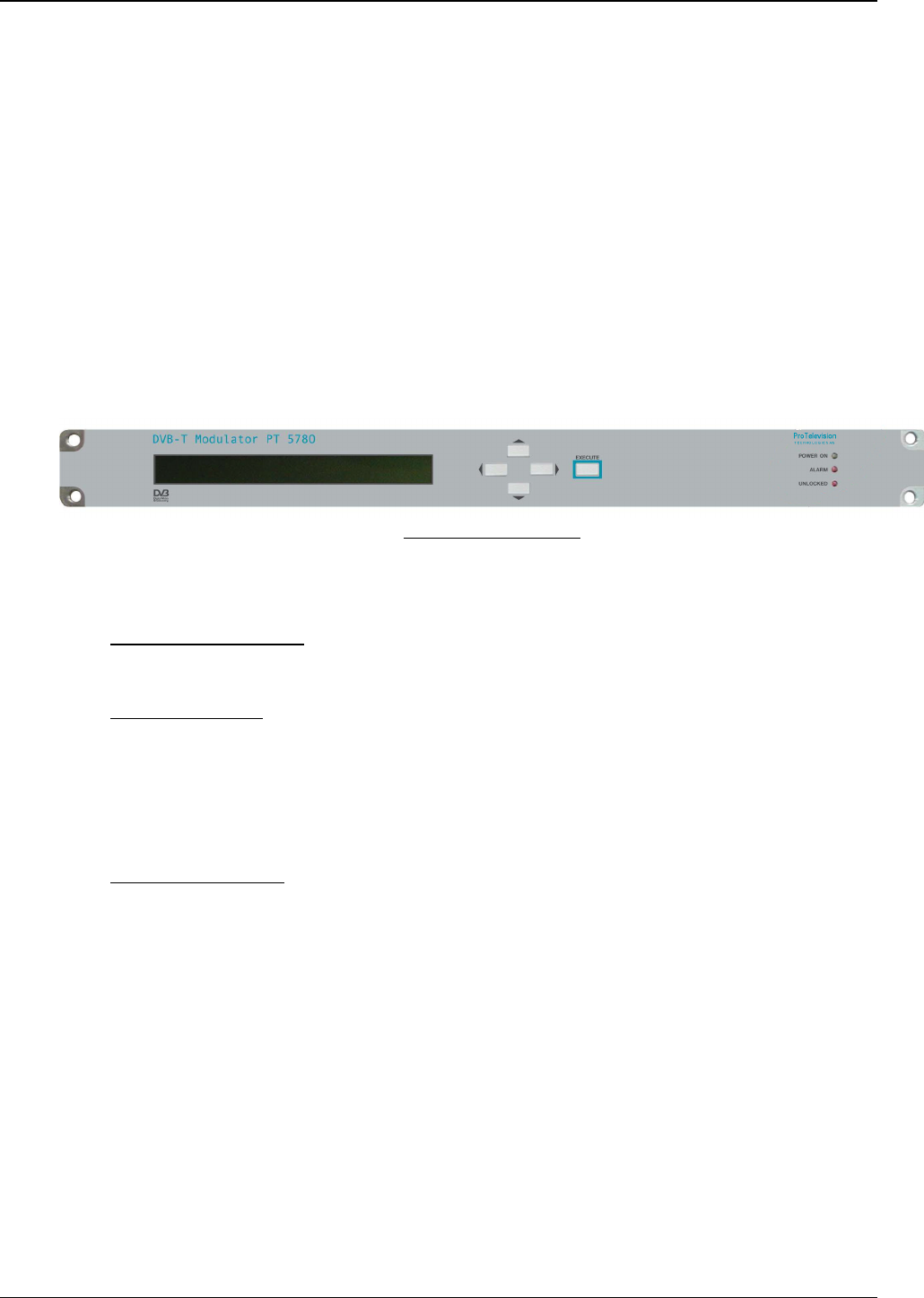
4.1 Front Panel
All operational control and configuration are conveniently carried out from the front panel.
The two line by forty characters LCD display, in conjunction with four cursor keys and an
EXECUTE button, allows easy operation of the PT 5780 DVB-T Modulator.
The display is used to indicate the status of various system parameters and also allows
changes to be made to these system parameters.
The cursor keys and EXECUTE button are used to navigate through the menu system and to
configure system parameters.
Front of the Instrument
4.1.1 Front Panel Indicators
Green POWER ON LED
When lit up, the green LED indicates that power is available from the supply.
Red ALARMS LED
This LED indicates the presence of an irregularity when any of the alarm conditions (e.g. “Sync
Loss”, “Reference Loss”, etc) are “active” AND they have been configured to output to one of
the relays. See Chapter 4.3.4.5 Alarm menu system for more details.
In addition this LED may flash. This occurs when there is a test signal active.
Red UNLOCKED LED
When lit up, the red LED indicates failure of the modulator in synchronizing to the incoming
transport stream or external frequency reference signal.
Note that the Alarm & Unlocked LEDs flash when the DVB-T modulator output is muted. Note
that the output in SFN mode will mute irrespective of the general programming of mute
conditions until the modulator have established synchronising to the timing references (1PPS,
10MHz and MIP).
4.1.2 Front Panel Controls (The menu system)
For cursor buttons and an execute button plus an LCD display are available for front panel
control of the DVB-T Modulator. The front panel functions are divided between read-out of
status information (transmission mode, output frequency, alarm status, etc.) and actual
setting/change of parameters that will affect the modulator output. To navigate between the two
functionalities (status and configuration) please refer to the drawing in figure 4-1

Operating Instructions ProTelevision Technologies PT 5780 DVB-T Modulator
Instruction Manual Revision 3.11 4-2
Status Menu System
Configuration Menu System
Push [EXECUTE] button
and [RIGHT ARROW] button
in sequence to enter the
Configuration Menu System
(note 1).
Push [UP ARROW] button
to return to the Status Menu
System.
Note 1: Activates the Configuration Menu System at the top-level default entry point (Menu ID 1000 - <TRANSMISSION>). Alternatively, by pushing
the [EXECUTE] key twice the Configuration Menu System will be activated at a sub menu relevant to the currently selected status display. For
example, pushing [EXECUTE] twice when the Input Status display is active will open the configuration sub menu for control of input configuration
Rev 3.0 23.01.2003
u/5780/work/manual v3/drawings/status and config system
Figure 4-1 Front panel menu system
Dependent on the specific function being operated via the front panel the cursor keys may have
the following functions:
The 55 button is used to either
• Scroll through the different sub displays provided within the status menu system (refer to
the enclosed Status Menu System diagram)
• Exit the current menu and enter a higher-level menu
• Increase alpha-numerical parameters
• Abort confirmation of a change
The 66 button is used to either
• Scroll through the different sub displays provided within in the status menu system (refer
to the enclosed Status Menu System diagram).
• Exit the current menu and enter a sub-menu
• Decrease alpha-numerical parameters
• Abort confirmation of a change
The 33 and 44 buttons are used to scroll between the main displays provided in the status menu
system (refer to the enclosed Status Menu System diagram) and to scroll between the functions
available in the configuration menu system.

PT 5780 DVB-T Modulator ProTelevision Technologies Operating Instructions
Instruction Manual Revision 3.11
4-3
The EXECUTE button is used to
• Enter the configuration menu system (GENERAL or SPECIFIC) when in the status menu
system.
• Confirm changes made to configurable parameters.
4.1.3 Front Panel Display
To guide the user through operations, symbols of the push buttons, which are active at that
particular time appear in the top right hand side of the display.
3and 4indicate that the left and right arrow buttons can be used; a 5indicates that the up
button can be used; a 6 indicates that the down button can be used; a v indicates that both
the up and down buttons can be used; and an E indicates that the EXECUTE button can be
used.
55 66 33 44 Indicates which arrow buttons are active.
E Indicates that the EXECUTE button must be pressed to activate the required
selection.
<< >> These flashing brackets indicate the position of the cursor when in a menu
option listing, also described as the “current” menu option in this manual.
[ ] These flashing brackets indicate the position of the cursor when in a
enumerated parameter listing or when in a parameter set listing. Also
described as the “current” parameter in this manual.
…… Indicates that more items are available in the menu option or parameter listing
than can be fitted in the display. Scrolling right with the 4 button will display
these items.
Guide to Menu Display
In addition, the top line of the display also usually shows the current menu option and status.
The bottom line of the display indicates possible menu options or parameter settings.
4.2 Rear Panel
4.2.1 Rear Panel Connections
Safety Ground (chassis)

Operating Instructions ProTelevision Technologies PT 5780 DVB-T Modulator
Instruction Manual Revision 3.11 4-4
Mains Connector
Mains voltage receptacle with ON/OFF switch.
ON: When “I” is pressed.
OFF: When “O” is pressed.
Input Connectors A and B
Two BNC inputs (A and B) are provided for asynchronous serial transport streams (ASI).
Remote Connectors 1 and 2
Two 9 pole male Sub-D connectors are utilised for the remote connectors. They are configured
as RS 232 connections. For configuration of these connectors refer to the CONFIGURE menu
system in Chapter 4.3.4.7.
Monitor Output Connector
A BNC connector (ASI format1) is provided for output monitoring purposes.
Alarms Connector
A 9 pole male sub-D connector of floating-contact type is provided to connect the two alarm
switches to external alarm indicators. The connector also includes contact points for ground-
closure activated output muting and instrument reset. For connections, refer to the Installation
chapter of this manual. For configuration of alarms, refer to Chapter 4.3.4.5 Alarm menu
system.
Reference Inputs
1 PPS - A BNC connector is provided for a 1 pulse per second input signal for SFN
synchronization.
10 MHz - A BNC connector is provided for an external frequency reference input of 10 MHz.
IF Output
A BNC connector (with a 50 impedance) is provided for the IF output signal.
IF/RF Output A
An N-type connector (with a 50 impedance) is provided for the main IFR/RF OFDM output.
IF/RF Output B
An N-type connector is also provided for an optional IF/RF output signal.
Rear of the Instrument
1 When monitoring the internally processed MPEG-2 streams (Demodulator output or the TSA
adapted input) the clocking out of the useful data takes place during the actual COFDM symbol
– no data is clocked out during the COFDM signals guard interval (the data stream is therefore
of a bursty nature)
ASI IEEE 1394MONITOR10MHZ1PPS ALARMS
IF/RF OUTPUTS
MAINS FUSE 2x 1.25A SLOW BLOW
IF
OUTPUT OUTPUT INPUT BREF. INPUTS ASI IEEE 1394
INPUT A
REMOTE 1
A B
REMOTE 2
ETHERNET CE
IF/RF
INPUT

PT 5780 DVB-T Modulator ProTelevision Technologies Operating Instructions
Instruction Manual Revision 3.11
4-5
This text is a site specific
identification and can be modified by
the customer via the Remote
Interface only.
The current date and time is
displayed until the back-end control
ler
is powered up.
The software release is momentarily
displayed before the modulator enters
the first status window.
4.3 Menu System – Description and Operation
The PT 5780 DVB-T Modulator is equipped with different functions dependent on the purchased
options.
An operating menu chart, which reflects the structure of the menu system when all possible
functions are installed and enabled, is provided in appendix A..
The menu system is designed as a “tree” structure, with a number of different “branches”. Each
“branch” is made up of a “menu options”. The lowest “branch” contains a configurable menu
option with a list of parameters to choose from.
Note that additional configurable options are available via remote access/control. See Chapter
6.2.3.
The menu system has two main functions:-
1. system status display - the display of various modulator configuration settings through
“status windows”
2. system configuration - the ability to modify the modulator’s configuration settings through
“configuration windows”.
On start up the modulator always enters the system status menu.
There are two ways to enter the configuration menu system; by pressing [EXECUTE] followed
by the [RIGHT] arrow button the configuration system will be opened at the top level entry point
and the user will be able to navigate freely between all the menus. Alternatively, the user can
press [EXECUTE] twice to open the menu system at a sub menu relevant to the status menu
parameters being displayed when the key-press sequence is initiated. When using this
navigation method pressing the [UP] arrow key will recall the last status display.
4.3.1 Power Up
The start-up process includes the following status
windows:
----------------------------------------
PT5780 DVB-T Modulator PTV
- Power-up - 2001-07-08, 3:07:33
----------------------------------------
And later:
----------------------------------------
PT5780 DVB-T Modulator PTV
Release X.X ............................
----------------------------------------

Operating Instructions ProTelevision Technologies PT 5780 DVB-T Modulator
Instruction Manual Revision 3.11 4-6
In case new micro-code has to be installed, the
following is displayed:
----------------------------------------
**** R E C O N F I G U R I N G ****
=- micro-code being installed -=
----------------------------------------
Following successful start-up, the first status display window appears – see Chapter 4.3.3.1.
Switching the instrument off and then back on again retains all system configuration settings.
4.3.2 Operating Menu System Chart
A set of charts describing the menu system is provided (see appendix A) in order to
diagrammatically show the structure of the menu system, with the various menu options and
parameters. The charts enclosed are:
• Status Menu System
• Configuration Menu System (page 1 of 2)
• Configuration Menu System (page 2 of 2)
All menu windows in the menu system contain a four-digit number in the top right hand position.
This number is known as the menu identification number and is useful for referencing and
navigating purposes and is shown in “red” in the Menu System Charts. The menu-structure has
a maximum of four levels; hence the four-digit identification.
4.3.3 Status Menu System
If all hardware/software options are installed, enabled and turned on, the system status menu
consists of a maximum of eight main “status windows”. Each main “status window” can be
divided into a number of sub windows. The “status windows” display the settings of various
configurable options and system variables.
A description of each status window is provided below. Each status window is identified with a
flashing character (’a-n’ through to ’h-n’) in the lower right hand corner of the display (n is an
integer decimal value 1, 2, 3,… that identifies the specific sub window). These status window
identification characters flash at approximately 1 Hz to indicate that the device is running. If
preferred, the status display identifiers can be removed from the display altogether or left as a
constant display by using the CONFIGURE – STATUS MENU ID menu option. Chapter 4.3.4.7
describes how to configure this Menu ID.
As mentioned previously, certain status windows are only accessible if the appropriate
hardware/software options are installed.
The operator may navigate through the main status windows by using the left or right cursor
keys. Navigation between sub status windows is where applicable done by means of the up or
down arrow keys. On reaching the last or first status window the system loops round to the first
and last respectively.
The information in the status display windows are updated approximately every ½ sec.
The first line will flash. After new
micro-code has been
downloaded, the system
automatically reboots.

PT 5780 DVB-T Modulator ProTelevision Technologies Operating Instructions
Instruction Manual Revision 3.11
4-7
4.3.3.1 Description of Status Display Windows
Status Window ‘a1’ – The Input (or High Priority Input in the case of a hierarchical
system) Status Window
The example given here is for a hierarchical system:
----------------------------------------
INPUT HP: A ASI / 204 OK wv8E
Ref:Ext a1
----------------------------------------
Status Window ‘a2’ – The Low Priority Input Status Window
This window is only available when the hierarchical version of the modulator is in use. However
if the hierarchical mode is set to “NONE” through the menu TRANSMISSION – MODE –
HIERARCHICAL MODE, the following window is displayed, as there has been no hierarchical
alpha parameter configured:
----------------------------------------
INPUT LP: Non Hierarchical Mode wv8E
Ref: Int a2
----------------------------------------
However if the hierarchical alpha parameter is set to one of the hierarchical modes (alpha 1,
alpha 2 or alpha 4), the following window is displayed (assuming that input B has been selected
as LP source):
----------------------------------------
INPUT LP: B ASI / 204 OK wv8E
Ref:Int a2
----------------------------------------
The Input status windows show the data packet size, the input signal type and the source of the
10MHz system reference clock (Internal or External)
Status Window ‘a1’ – Signal loss vs. Auto Substitute function
When the modulator cannot detect an input signal and the auto substitute function is disabled,
the following input status window appears (assuming that input A signal source is lost in non-
hierarchical mode):
----------------------------------------
INPUT : A ASI No Sync wv8E
Ref:Int a1
----------------------------------------
Note: “No Sync” flashes.
If the input specified as primary source in non-hierarchical mode is lost when the auto substitute
function is enabled, the following input status window appears (assuming that the input
specified as secondary source (B) is available):
----------------------------------------
INPUT Prim: A ASI No Sync wv8E
Ref:Int Sec: B ASI /204 OK <Actual a1
----------------------------------------
Note: “No Sync” flashes.

Operating Instructions ProTelevision Technologies PT 5780 DVB-T Modulator
Instruction Manual Revision 3.11 4-8
Status Window ‘b1’ – The Mode Status Window
This window shows the output configuration settings: IFFT, constellation, Code rate, network
mode (MFN or SFN), hierarchical mode (none, a1, a2 or a4)), and guard interval. An example of
a mode status window for a non-hierarchical modulator configuration is:
----------------------------------------
MODE IFFT:8k, Cons:64QAM, CR-HP:1/2 wv8E
MFN Hier:None, Guard:1/32 b1
----------------------------------------
Status Window ‘b2’ – The Preset Status Window
This window displays the number and name of the preset whose settings are currently loaded
into the modulator.
----------------------------------------
PRESET wv8E
No: 3, Name: "Preset Name" b2
----------------------------------------
Status Window ‘c1’ (MFN config.) –TS Buffer fill indicator Status Window
This window is only available in MFN mode. It displays the number of transport stream
packages waiting in the input buffer (readings between 0 and 8 packages are considered
normal, the diaplayed valy may fluctuate if the bit rate of the applied stream is not constant).
----------------------------------------
TS Buffer fill indicator wv8E
2 packages c1
----------------------------------------
Status Window ‘c1’ (SFN config.) – The SFN delay status display
This window is only available in SFN mode. It displays the maximum network delay value
extracted from the MIP (100ns resolution) and the delay margin (1 ms resolution). The delay
margin is defined as the time (in ms) that a mega frame is stored in the input buffer before the
network-wide timing dictates transmission.
----------------------------------------
SFN Max Delay:350,000.0 ìs wv8E
Margin: 258ms c1
----------------------------------------
Status Window ‘c2’ – The SFN Setup Status Window
This window is only available in SFN mode. It displays the method used for controlling the
transmission parameters (control via TS control ON or OFF), the transmitter identification
number assigned to the modulator (TX ID), and the local delay offset value set via the <Signal>
à <Output> à <SFN DELAY> sub menu.
----------------------------------------
TS Control:ON, TX ID:55 wv8E
Local Delay 000,000.0 ìs c2
----------------------------------------
Status Window ‘c3’ – The SFN Optional Data Status Window
This window is only available in SFN mode. It displays the optional time offset, frequency offset
and power offset data values received via the MIP. The DVB-T Modulator implements only the

PT 5780 DVB-T Modulator ProTelevision Technologies Operating Instructions
Instruction Manual Revision 3.11
4-9
optional delay value. The modulator does not implement the frequency offset and the absolute
power value but both values can be extracted via the modulator remote control (SCPI/RS232)
for use by the transmitter control system if desired.
----------------------------------------
Optional Delay Time:-30.0 ìs wv8E
Freq:400 Hz Power:10.0 dBm c3
----------------------------------------
Status Window ‘d1’ – The Output Status Window
This status window displays the IF/RF (dependent on whether the RF converter is installed and
enabled for use) output frequency, the output bandwidth and the output level. The output level is
displayed in dB relative to nominal level.
If the RF converter is not installed, the following window is displayed:
----------------------------------------
OUT IF-Freq:36,000,000 Hz (8MHz) wv8E
Level:0.0 dB d1
----------------------------------------
note: Nominal IF level is +6dBm
If the RF converter is installed and enabled, the following window is displayed:
----------------------------------------
OUT RF-Freq:1,000,000,000 Hz(8MHz) wv8E
Level: 0.0 dB d1
----------------------------------------
note: Nominal IF level is 0dBm
Status Window ‘d2’ – The Pre-Corrector Status Window
This window is only available if the pre-corrector option PT 8731 is installed. On the first line of
the window, the display shows whether the non-linear and linear pre-correction functions are
currently in operation. On the second line the origin of the employed pre-correction curves is
indicated. The pre-correction curves can be loaded from the preset bank (in this case the
number and name of the preset is indicated). Alternatively, the curves originate from the default
pre-corrector curve bank (in this case the display will indicate: “No saved Pre-correction curve
loaded”. The default pre-corrector curve bank contains the curve that can be manipulated by
means of the IMD Buster PC software that is supplied together with the pre-corrector option.
The IMD Buster software allows transfer of the curve from the default curve bank to one of the
curve pre-set bank.
----------------------------------------
PRE-CORRECTOR NLC: ON, LC: ON wv8E
NLC:#1/2001-0-20T;LC:#7/2001-0-20R d2
----------------------------------------
----------------------------------------
PRE-CORRECTOR NLC: ON, LC: OFF wv8E
No saved pre-correction curve loaded d2
----------------------------------------
Note that the second line display is evenly split between the names of the non-linear and linear
pre-correction curves.

Operating Instructions ProTelevision Technologies PT 5780 DVB-T Modulator
Instruction Manual Revision 3.11 4-10
Status Window ‘f1’ – Demodulator Status Window
This window displays the status of the built-in COFDM demodulator. The COFDM demodulator
monitors, when enabled, the modulators IF output. If the output signal is a valid COFDM signal
the display will indicate the signals transmission parameters (IFFT, Constellation, Code rate,
Hierarchy, and guard interval.). If the output signal is not a DVB-T compliant COFDM spectrum
one or more of the parameter indications will be replaced by “—“ and the status indication
“Unlock” will be shown.
----------------------------------------
DEM1 IFFT: 8K Const: 64QAM CR: 2/3 wv8E
Locked Hier: None Guard: 1/16 f1
----------------------------------------
----------------------------------------
DEM1 IFFT: -- Const: -- CR: -- wv8E
Unlock Hier: -- Guard: -- f1
----------------------------------------
Status Window ’g1’ – The Alarm Status Window
The alarm status display provides a detailed description of the cause of any active (currently
present) alarm conditions. If more than one alarm are active simultaneously the individual
alarms can be observed one-by-one by scrolling through the list by means of the UP or DOWN
cursor keys. If the “Auto Open Alarm Window” mode is enabled via the configuration menu
(default setting), the alarm status window will automatically be opened (displayed) whenever an
alarm is raised.
Example 1 (no active alarms, last active alarm was “Sync Loss”)
----------------------------------------
ALARMs: Sync Loss wv8E
0 Not active
----------------------------------------
Example 2 (One active alarm : “Sync Loss”, High priority input)
----------------------------------------
ALARMs: Sync Loss wv8E
1 HP
----------------------------------------
Example 3 (Four active alarms, use the UP or DOWN cursor keys to view each of the four
alarms)
----------------------------------------
ALARMs: Sync Loss wv8E
4 HP
----------------------------------------

PT 5780 DVB-T Modulator ProTelevision Technologies Operating Instructions
Instruction Manual Revision 3.11
4-11
Additional information about each alarm can be obtained via the configuration sub menu
<ALARM> –-> <ALARM INFORMATION> menu ID 3200 (accumulated count of the alarm type
and specific information for generic alarms). The event log configuration menu <EVENTLOG>
à <VIEW> menu ID 8100 may provide information abut the exact start and stop time for each
type of alarm (requires that the alarm type has been routed to the event log by specifying Event
Log “on” for the alarm type in the configuration sub menu <ALARM> –-> <DEFINE ALARM
SYSTEM> menu ID 3100.
If an alarm is “unstable” and alternates between being active and inactive AND the
<CONFIGURE> – -> <AUTO OPEN ALARM WINDOW> (menu ID 5300) is set to “On” the
alarm display will be opened automatically as explained above. However, to allow uninterrupted
operation of the instrument via the front panel during repeated occurrence of an intermittent
alarm the alarm window will not open until five seconds after the last key-press of any front
panel key have taken place.
Status Window ’h1’ – The Test Signal Status Window
----------------------------------------
TEST SIGNAL ACTIVE wv8E
Single Carrier h1
----------------------------------------
This status window displays the current test signal configuration and is only available if a test
signal is active via the <TEST SIGNAL> – -> <SELECT TEST> sub menu Menu ID 6000. Note
that the test signal menu is only available if the TEST SIGNAL lock in the sub menu
<CONFIGURE> –-> <LOCK> menu ID 5100 is “OFF”.
4.3.4 Configuration Menu System
Two methods for accessing the configuration menu system exist. The first step is always to
push the [EXECUTE] button. This action will open the following display:
----------------------------------------
Entering Menus, Press Right Arrow wv8E
or EXECUTE for specific...
----------------------------------------
note: the display will close automatically after about 3 seconds if the user does not press the [RIGHT ARROW] key or the [EXECUTE] key
Top-level menu access
Pressing the [RIGHT ARROW] button during the above display mode will open the
configuration menu system at the default entry point (Transmission parameters, menu ID 1000).
For further details see paragraph 4.3.4.1
Context sensitive menu access
Pressing the [EXECUTE] button during the above display mode will open directly the
configuration sub menu that is related to the status menu window in which the activation of the
configuration menu system was initiated. For further details see paragraph 4.3.4.2. Note: when
entering the menu system via the context sensitive method it’s not possible to navigate to a
different menu without first exiting the configuration menu system (pressing the [UP] arrow key).

Operating Instructions ProTelevision Technologies PT 5780 DVB-T Modulator
Instruction Manual Revision 3.11 4-12
4.3.4.1 Top-level configuration menu access
To enter the configuration menu at the top level of the menu hierarchy press the [EXECUTE]
button followed by the [RIGHT ARROW] button. After pressing the [EXECUTE] button the below
display will be shown. If the [RIGHT ARROW] button is not pressed within about 3 seconds the
display will close automatically and return to the last open status window.
----------------------------------------
Entering Menus, Press Right Arrow wv8E
or EXECUTE for specific...
----------------------------------------
The <TRANSMISSION> menu (ID 1000) is the top-level entry point in the menu hierarchy. The
complete hierarchy is provided in the attached menu structure diagrams.
All menu windows in the configuration menu system contain a four-digit number in the top right
hand position. This number is known as the menu identification number and is useful for
referencing purposes. The menu-structure has a maximum of four levels; hence the four-digit
identification. See examples below.
Examples of the top level of the configuration menu system are shown below in Examples A
and B. The character string “DVB-T Modulator“ is always positioned on the left hand side of
the display when in the top level of the configuration menu system. The available menu items
are shown on the second line and may be scrolled through using the 33 and 8 buttons.
The “current” menu option is always shown in capitalised format with flashing “< >” brackets. If
more menu options are possible than the display allows, three (3) dots are shown in the lower
right position.
Example A
----------------------------------------
DVB-T Modulator <1000>wv8
<TRANSMISSION> Signal Alarm Preset ...
----------------------------------------
Pressing8 produces Example B:
----------------------------------------
DVB-T Modulator <2000>wv8
<SIGNAL> Alarm Preset Configure Te...
----------------------------------------
Moving down a level to the next menu option by pressing the 66 button produces a display like
that shown in Example C.
Example C
----------------------------------------
Signal, Input [2110: ON]wv8
<AUTO SUBSTITUTION> Input
----------------------------------------
The “current” parameter is shown in the top right hand side of the display together with the
menu identification number, which is surrounded by square brackets. If the parameter name is

PT 5780 DVB-T Modulator ProTelevision Technologies Operating Instructions
Instruction Manual Revision 3.11
4-13
longer then 8 characters, the name is truncated and a dot (.) is included as the 8th character. In
a few cases, the “current” parameter is automatically updated in the display window, e.g. the
Clock.
The lowest level of any particular “branch” of the menu system produces a window that displays
the available parameter list, a configurable value or a non-configurable value. At this level the
only information given in the upper right hand corner is the menu identification number.
If a parameter list is obtained (see Example D), the “current” parameter is always the first item
and is capitalised and surrounded by flashing square brackets.
Example D -------------------------------------------
Signal, Input, Auto Substitute <2110>w58E
[ON] off
-------------------------------------------
If an editable value is accessed (see Example E) the current parameter value is shown in the
bottom left hand side of the display. The last digit of the “current” parameter value flashes to
indicate that this digit will be changed if the [UP] or [DOWN] keys are pressed. The other digits
of the value can be edited by navigating to the digit using the [LEFT] or [RIGHT] keys. The valid
range for the parameter is indicated in square brackets in the bottom right hand side of the
display.
Example E ----------------------------------------
Sig.Out. RF Level (dB) <2250>wv8E
00,0 [-10.0 ..0.0]
----------------------------------------
Finally if a non-configurable parameter value is accessed the window shown in Example F is
displayed. The menu parameter is enclosed in and brackets, whilst the “current”
parameter value is shown in the upper right hand corner of the menu window, with no brackets.
Example F ----------------------------------------
Instrument Identity 123456 w58
INSTRUMENT KU NUMBER
----------------------------------------
4.3.4.2 Context sensitive menu access
To use the context sensitive menu access press the [EXECUTE] button twice. After the first
pressing of the EXECUTE button the below window will open. If the EXECUTE button is not
pressed a second time within about 3 seconds the window will close automatically and return to
the last open status window.
----------------------------------------
Entering Menus, Press Right Arrow wv8E
or EXECUTE for specific...
----------------------------------------

Operating Instructions ProTelevision Technologies PT 5780 DVB-T Modulator
Instruction Manual Revision 3.11 4-14
The context sensitive access to the configuration system will open directly the configuration sub
menu that is related to the status menu window in which the activation of the configuration
menu system is initiated. For example, pressing [EXECUTE] à [EXECUTE] when the “Input
status” display is active will open the <SIGNAL> à <INPUT> sub menu for configuration of
input source. Likewise, pressing [EXECUTE] à [EXECUTE] when the “output status” display is
active will open the <SIGNAL> à <OUTPUT> sub menu for configuration of frequency, level,
etc.
Status menu Associated configuration menu
(accessed by pressing [EXECUTE] à [EXECUTE])
Input Status (a1, a2) <SIGNAL> <INPUT> menu ID 2120
Mode Status (b1) <TRANSMISSION> <MODE> menu ID 1200
TS Buffer fill (c1 - MFN) <TRANSMISSION> menu ID 1000
TS Control Status (c2 – SFN) <TRANSMISSION> <SFN TS Control> menu ID 1100
Optional Time, Freq,(c3 –SFN) <TRANSMISSION> <SFN TS Control> menu ID 1100
Output Status (d1) <SIGNAL> <OUTPUT> menu ID 2200
Pre-Corrector status (d2) <SIGNAL> <Non-Lin Pre-Corrector> menu ID 2300
Alarm status (g1) <ALARM> <DEFINE ALARM SYSTEM> menu ID 3100
Table 4-1 Context sensitive menu access
4.3.4.3 TRANSMISSION Menu System (Menu ID 1000)
The top level of the transmission menu system (menu ID 1000) is accessed by pressing the
[EXECUTE] button followed by the [RIGHT ARROW] button as described in paragraph 4.3.4.1.
By applying the [LEFT] , [RIGHT] , [UP] , [DOWN] keys as required (see attached Configuration
Menu System diagram) it is possible to navigate to a number of sub menus:
SFN TS Control (ID 1100)
This menu, which is only available when the instrument is configured for SFN mode, allows the
user to select if the transmission parameters (constellation, guard interval, code rate, hierarchy)
are to be controlled via the MIP (default setting) or if the parameters are to be set manually. If
the manual mode is selected it is the operators responsibility to ensure that the selected
parameters correspond to the parameters applicable to the transport stream to be transmitted. If
the manually selected parameters do not match those applicable to the applied transport stream
transmission in SFN mode is not possible (output will be muted).
MODE (ID 1200)
This menu allows the user to select the COFDM parameters for the transmission. Sub menus
are available for setting Hierarchy (if hierarchical option is installed), IFFT, Code rate
constellation and guard interval. The mode menu cannot be accessed if SFN TS control is set to
“ON”.

PT 5780 DVB-T Modulator ProTelevision Technologies Operating Instructions
Instruction Manual Revision 3.11
4-15
MFN/SFN (ID 1300)
The menu allows selection of the network mode to be applied for the transmission; Multi
Frequency Network – MFN or Single Frequency Network – SFN. Note: The menu is only
accessible when the SFN option PT 8732 is installed.
4.3.4.4 SIGNAL Menu System (Menu ID 2000)
The signal menu system (menu ID 2000) is accessed by pressing the [EXECUTE] button
followed by the [RIGHT ARROW] button as described in paragraph 4.3.4.1. When the menu
system is entered at menu TRANSMISSION use the [RIGHT ARROW] button to navigate to the
SIGNAL menu.
INPUT menu (ID 2100)
This menu allows the user to select the input source(s) and to set the status of the auto
substitution function.
In the non-hierarchical configuration the input menu (ID 2120) allows the user to assign a
primary input source and a secondary input source. The instrument offers as standard a choice
between two input sources (ASI input “A” and ASI input “B” corresponding to the BNC input
sockets located in the rear panel of the modulator). Additional input sources such as two more
ASI inputs (input “C” and “D” ) or an SPI LVDS input are available as options (When installed
the SPI LVDS input is identified as input “C”).
For non-hierarchical applications the user will typically program input ”A” as the “primary” and
input “B” as the “secondary” input source. Should the “primary” signal source fail in this
configuration the instrument will automatically switch over to the “secondary” input if the Auto
substitution function is set to “ON” (requires that a valid MPEG-2 transport stream is applied to
the “secondary” input).
For hierarchical applications the user will typically assign input “A” as primary source for the
High Priority input (Menu ID 2120) and assign input “B” as primary source for the Low Priority
input (menu ID 2130). If the option that provides two additional ASI inputs is installed (Input “C”
and “D”) the user may choose to program Input C as secondary input source for the High
Priority input (menu ID 2120) and to program Input D as secondary input source for the Low
Priority input (menu ID 2120) if it desired to add redundancy by means of the Auto Substitution
function. That is, when the auto substitute function is set to “ON” the unit will automatically
switch to the secondary input source if the primary input source fails (requires that a valid
MPEG-2 transport stream is applied to the “secondary” input).
OUTPUT (ID 2000)
This menu allows the user to set a range of parameters that affect the generated COFDM
spectrum. Sub menus are available for setting (centre) frequency, bandwidth, level, sideband
filter (window) function, spectrum polarity, and local transmission delay (SFN only).
A sub menu (menu ID 2210) allows the user to set the output frequency. The IF version allows
setting of the frequency in the range between 35-37MHz. The RF version covers the range from
30MHz to 1000MHz. Note: In case of the RF version (option PT 8715 installed) the IF output is
fixed to 36MHz. The RF version allows furthermore the user to set the output frequency by
channel number (menu ID 2220). The applicable channel raster is programmable via the
channel set-up menu (menu ID 2230). The channel set-up menu offers selection between a

Operating Instructions ProTelevision Technologies PT 5780 DVB-T Modulator
Instruction Manual Revision 3.11 4-16
choice of standard channel rasters (ITU UHF combined with either the VHF B, VHF L or VHF I
raster) and a user defined channel raster. When the user-defined raster is selected the user can
configure this raster via sub menu 2231 with respect to base frequency and start channel
number. The ‘base frequency’ represents the centre frequency of the first channel in the user-
defined raster (for example 529,5 MHz). The ‘start channel number’ represents the number to
be assigned to the first channel in the user-defined raster (for example 28). The step size of the
channel raster will always follow the bandwidth of the modulator (for example 7MHz). These
three parameters values (529,5 MHz, ch no. 28, BW 7MHz) provides a channel raster that steps
as follows: CH28: 529,5MHz, CH29: 536,5MHz, CH30: 543,5MHz ……….(Australian UHF
System B)
The bandwidth sub menu (ID 2240) allows the user to switch the bandwidth of the COFDM
spectrum between 8, 7 and 6MHz (6MHz bandwidth requires that option PT 8735 is installed).
The Output Level sub menu (ID 2250) allows the user to set the Output level. The adjustment
range for the IF version is +2/-8dB in steps of 0.1dB relative to nominal output level +6dBm. For
the RF version the adjustment rage is +0dB/-10dB relative to nominal output level (0dBm). Note:
In case of the RF version (option PT 8715 installed) the IF output level is fixed to +6dBm
The Window On/Off sub menu (ID 2260) allows the user to switch on/off the “window” type
spectrum sideband filter function as required (as default the filter is switched on).
The Window RollOff sub menu (ID 2270) allows the user to adjust the trade-off between
obtained sideband suppression and cross talk between two successive COFDM symbols. The
default window ratio 1/64 provides maximum sideband suppression.
The Spectrum sub menu (ID 2280) allows the user to set the polarity of the spectrum as
required. When NORMAL polarity is selected carrier number 1 of the COFDM spectrum is
located at the lowest frequency whereas the last carrier number (1705 by 2K and 6817 by 8K) is
located at the highest frequency. When inverted polarity is selected carrier number 1 of the
COFDM spectrum is located at the highest frequency whereas the last carrier number (1705 by
2K and 6817 by 8K) is located at the lowest frequency. Note: for the RF version the selected
spectrum polarity refer to the RF output (the IF output will have the opposite polarity of the
polarity selected for the RF output).
The SFN Delay sub menu (ID 2290) allows the user to set a local delay offset relative to the
transmission timing specified via the MIP (the menu is only available in SFN mode). The
nominal adjustment range is +/- 999.999,9 ms in steps of 100ns. However, in practice the
applied value must respect the timing window set by the actual propagation delay from the
head-end to the modulator relative to the network delay specified in the MIP (maximum delay).
The transmission time cannot be advanced beyond the actual propagation delay from the head-
end to the modulator (the modulator must obviously receive the mega frame before it can
transmit it).
Non-Linear Pre-Correction (ID 2300)
This menu allows the user to control the non-linear pre-corrector function (only available when
option PT 8731 is installed). Sub menus are available for switching the pre-corrector function
on/off (menu ID 2310), for setting the gain of the pre-corrector (menu ID 2320), for setting the
peak clipping menu (ID 2330), and for recalling a correction curve from the preset library (menu

PT 5780 DVB-T Modulator ProTelevision Technologies Operating Instructions
Instruction Manual Revision 3.11
4-17
ID 2340). The menu for setting the peak clipping level allows the user to control the ratio
between peak power and average RMS power of the COFDM spectrum. If the clip level is set to
0dB the peak power is limited to +17dB relative to average RMS power. If the clip level is
increased to 4dB the peak power relative to average RMS power will be limited to 13dB. The
average RMS power remains unchanged.
Peak level = 17dB – clip level – precorrector gain
The clip function is implemented as hard clipping without band limitation. The definition of pre-
correction curves must be done via the remote interface by means of the separate PC software
tool (IMD Buster) supplied with the pre-corrector option.
Linear Pre-Correction (ID 2400)
This menu allows the user to control the linear pre-corrector function (only available when
option PT 8731 is installed). Sub menus are available for switching the linear pre-corrector
function on/off (menu ID 2410) and for recalling a correction curve from the preset library (menu
ID 2420). The definition of pre-correction curves must be done via the remote interface by
means of the separate PC software tool (IMD Buster) supplied with the pre-corrector option.
Monitor (ID 2500)
This menu allows the user to specify which signal that is to be routed to the monitor output
located in the rear panel of the DVB-T modulator. It is possible to monitor the following signals:
Menu choice Description Remarks
HP Input Monitors the selected input
(HP input by hierarchical
mode) before any processing
has taken place
HP Output Monitors the selected input
(HP input by hierarchical
mode) after the transport
stream bit rate adaptation has
taken place.
LP Input Monitors the selected LP input
before any processing has
taken place
Only available in hierarchical
mode
LP Output Monitors the selected LP input
after the transport stream bit
rate adaptation has taken
place.
Only available in hierarchical
mode
Demodulator Monitors the output from the
on-board COFDM
demodulator (i.e. the transport
stream obtained by
demodulating the modulators
IF output)

Operating Instructions ProTelevision Technologies PT 5780 DVB-T Modulator
Instruction Manual Revision 3.11 4-18
Reference input (ID 2600)
This menu allows the user to select the 10MHz clock reference source and to configure
parameters with respect to the 10MHz and 1PPS reference inputs. Sub menus are available for
selecting 10MHz source (menu ID 2610), impedance for the 1PPS reference input (menu ID
2620), impedance for the 10MHz reference input (menu ID 2630), and trigger level for the 1pps
input.
The 10MHz reference source can be set to Internal, External or Auto. By auto mode the unit will
synchronize to an external reference if available and automatically switch to the internal
reference if no external reference is available (no alarm will be raised if the unit switches to
internal reference). By external reference mode the unit will synchronize to an external 10MHz
when available and switch to the internal reference if no external reference is available (an
alarm will be raised if the unit in this mode needs to switch to internal reference due to absence
of external reference). Note: for SFN mode external reference should be selected.
4.3.4.5 ALARM Menu System (Menu ID 3000)
The alarm menu system (menu ID 3000) is accessed by pressing the [EXECUTE] button
followed by the [RIGHT ARROW] button as described in paragraph 4.3.4.1. When the menu
system is entered at menu TRANSMISSION use the [RIGHT ARROW] button to navigate to the
Alarm menu.
Define Alarm menu (ID 3100)
This menu allows the user to program the desired response for each of the possible alarms that
can be raised by the unit. For each type of alarm the user can choose to route the alarm to one
or several of the following destinations:
Alarm destination Description
Mute When the Mute option for an alarm is set to “ON” the alarm will
be routed to the mute control circuit. In this case the modulator
output will mute whenever the alarm is active.
Event Log When the Event Log option for an alarm is set to “ON” the alarm
will be routed to the Event Log. In this case the time and date
when the alarm is raised and the time and date when the alarm
is lowered will be recorded in the event log together with the
specific name of the alarm type.
Relay 1 When the Relay 1 option for an alarm is set to “ON” the alarm
will be routed to Alarm 1 relay control circuit. In this case the
Alarm 1 relay contacts will be activated whenever the alarm is
active. The red ALARM led located in the front panel will be on
for the duration of the alarm.
Relay 2 When the Relay 2 option for an alarm is set to “ON” the alarm
will be routed to Alarm 2 relay control circuit. In this case the
Alarm 2 relay contacts will be activated whenever the alarm is
active. The red ALARM led located in the front panel will be on
for the duration of the alarm.

PT 5780 DVB-T Modulator ProTelevision Technologies Operating Instructions
Instruction Manual Revision 3.11
4-19
There are a total of 13 possible alarm types. Five of the alarm conditions are independent of the
instrument version while eight of the alarm conditions are only available for specific instrument
configurations.
ID Number Alarm Source/Condition Description
1 Sync and/or Data Loss Package sync byte (47H) missing and/or
no input data activity (stuffing only). By
hierarchical mode the affected stream will
be indicated (HP and/or LP)
2 Data rate Input data rate too high (overflow). By
hierarchical mode the affected stream will
be indicated (HP and/or LP)
3 COFDM Error detected in the COFDM parameters
of the output signal (code rate, guard
interval, constellation and hierarchy).
Note: This alarm is only available when
the built-in demodulator (Demodulator-1)
is configured for monitoring of the output
signal
4 10MHz reference loss 10MHz reference not available
5 System error Internal malfunction alarm
6 Timing adjusted Indicates that the modulator has adapted
the internal system clock or internal
1PPS timing to allow for a mismatch
between the local network timing
reference (10MHz and 1PPS) and the
timing reference (MIP) embedded in the
incoming transport stream.
NOTE: ONLY AVAILABLE WITH SFN
OPTION PT 8732
7 1PPS Reference loss Indicates that external 1PPS reference is
absent (operation may continue based on
internal 1PPS provided instrument was
correctly synchronised before loss of
external 1PPS).
NOTE: ONLY AVAILABLE WITH SFN
OPTION PT 8732
8 Mega-Frame (MIP) Loss Indicates that no valid MIP is available in
the applied transport stream.
NOTE: ONLY AVAILABLE WITH SFN
OPTION PT 8732
9 RF converter / “type” Indicates that an alarm of the specified
type has been raised for the RF
converter module (for specific alarm
types see below).
NOTE: ONLY AVAILABLE WITH RF
CONVERTER OPTION PT 8715
Continued:

Operating Instructions ProTelevision Technologies PT 5780 DVB-T Modulator
Instruction Manual Revision 3.11 4-20
continued from previous page:
ID Number Alarm Source/Condition Description
10 RF tuner / “type” Indicates that an alarm of the specified
type has been raised for the RF tuner
module (for specific alarm types see
below).
NOTE: ONLY AVAILABLE WITH DVB-T
RE-MODULATOR PT 5788
11 RF Tuner level Indicates that the RF input level has
dropped below the threshold specified via
the <Alarm> <Alarm Limits> <RF
Tuner…> submenu.
NOTE: ONLY AVAILABLE WITH DVB-T
RE-MODULATOR PT 5788
12 Demodulator 1 / “type” Indicates that an alarm of the specified
type (BER pre-Viterby, BER-post Viterby
and UCE) has been raised to signal that
the associated threshold has been
exceeded. The thresholds are specified
via the <Alarm> <Alarm Limits>
<Demodulator 1 Alarm Limits> submenu.
NOTE: ONLY AVAILABLE WITH DVB-T
RE-MODULATOR PT 5788
13 Demodulator 2 / “type” Indicates that an alarm of the specified
type (BER pre-Viterby, BER-post Viterby
and UCE) has been raised to signal that
the associated threshold has been
exceeded. The thresholds are specified
via the <Alarm> <Alarm Limits>
<Demodulator 2 Alarm Limits> submenu.
NOTE: ONLY AVAILABLE WITH
DEMODULATOR-2 OPTION PT 8722
In addition to the name of the alarm condition, further information may be available in the status
window or the ALARM INFORMATION “Additional Information” menu:
Alarm condition Additional information
Sync and/or Data Loss HP, LP or HP+LP
RF Converter No HW (No hardware), TEMP (Temperature tolerance
exceeded), 10V (10V supply voltage out of range),
LO1 (Local Oscillator 1 voltage out of range), LO2
(Local Osc. 2 voltage out of range), REF (Reference
voltage out of range), DDS (Direct Digital Synthesis
circuit out of lock)
RF Tuner TBA
System Error Various – contact ProTelevision Technologies

PT 5780 DVB-T Modulator ProTelevision Technologies Operating Instructions
Instruction Manual Revision 3.11
4-21
Alarm Information menu (ID 3200)
This menu allows the user to access further information concerning the status of the various
alarms. For each alarm type a separate sub menu is available which provides information about
whether the alarm is currently active, indicates the total number of times the alarm has been
raised since the alarm counter was reset and, where applicable, more detailed information
about the nature of the alarm (for example, in case of “Sync Loss” alarm it will be indicated if
the sync loss pertains to the HP or the LP input.
Do notice that the Alarm Counters are reset via the separate sub menu Reset Alarm Counter
(ID 3500).
Reset Alarm Counter menu (ID 3300)
This menu allows the user to reset the alarm counters. The menu features both a common
alarm reset option (Reset all) and facilities for resetting the counters on an individual basis. Note
that the alarm counters will automatically reset on reaching a count of 65536.
Alarm Limits menu (ID 3400)
This menu allows the user to set the threshold for the alarms that are triggered when exceeding
a specific parameter value. Subject to the options installed sub menus are available setting the
threshold of the temperature alarm, the RF level alarm (only with PT 5788), and of the bit error
alarms (only with PT 5788).
• Controller Board Temperature (sub-menu ID 3410): Allows user specification of the
internal instrument temperature at which the temperature alarm is to be raised.
ProTelevision Technologies recommends that the default threshold 82 °C be not exceeded.
• RF Tuner input level (sub-menu ID 3420): Allows user specification of the minimum RF
input level accepted. If the received level drops below this threshold the RF Tuner Input
Level alarm will be raised (10 – 100dBuV , default value is 10dBuV). Note: This function is
only available with DVB-T Re-Modulator PT 5788.
• Demodulator 1 Alarm Limits (sub-menu ID 3430): User definition of the BER and UCE
counts above which the Demodulator 1 alarm will be raised. Only available with PT 5788.
§ Pre-Viterby BER (sub-menu ID 3431): User definition of the bit error rate threshold
above which the demodulator-1 alarm for Pre-Viterby bit error rate is raised. Default
bit error rate threshold is 1E-2. The adjustable range is 1E-9 to 1E-1.
§ Post-Viterby BER (sub-menu ID 3432): User definition of the bit error rate
threshold above which the demodulator-1 alarm for Post-Viterby bit error rate is
raised. Default bit error rate threshold is 1E-4. The adjustable range is 1E-10 to 1E-
1.
§ UCE (sub-menu ID 3433): User definition of the UCE counter value at which the
demodulator-1 alarm for UCE is raised. Default UCE count is 10000. The adjustable
range is 1 to 1000. Count of an UCE (uncorrectable error) is equivalent to detection
of an Uncorrectable MPEG-2 TS packet (UP) as described in section 6.2 of the ETR
290 measurement guidelines (the demodulators Reed-Solomon error correction
overloaded by excessive bit error rate). The UCE counter is reset to zero count via
the sub-menu <RECEPTION> à <DEMODULATOR 1> à <RESET UCE>
• Demodulator 2 Alarm Limits (sub-menu ID 3440): User definition of the BER and UCE
counts above which the Demodulator 2 alarm will be raised (only available when option PT
8722 is installed).
§ Pre-Viterby BER (sub-menu ID 3441): User definition of the bit error rate threshold
above which the demodulator-2 alarm for Pre-Viterby bit error rate is raised. Default
bit error rate threshold is 1E-2. The adjustable range is 1E-9 to 1E-1.

Operating Instructions ProTelevision Technologies PT 5780 DVB-T Modulator
Instruction Manual Revision 3.11 4-22
§ Post-Viterby BER (sub-menu ID 3442): User definition of the bit error rate
threshold above which the demodulator-2 alarm for Post-Viterby bit error rate is
raised. Default bit error rate threshold is 1E-4. The adjustable range is 1E-10 to 1E-
1.
UCE (sub-menu ID 3442): User definition of the UCE counter value at which the demodulator-2
alarm for UCE is raised. Default UCE count is 10000. The adjustable range is 1 to 1000. Count
of an UCE (uncorrectable error) is equivalent to detection of an Uncorrectable MPEG-2 TS
packet (UP) as described in section 6.2 of the ETR 290 measurement guidelines (the
demodulators Reed-Solomon error correction overloaded by excessive bit error rate). The UCE
counter is reset to zero count via the sub-menu <RECEPTION> à <DEMODULATOR 2> à
<RESET UCE>.
Auto Open Alarm Window (ID 3300)
This menu allows the user to select whether the unit shall switch automatically to the alarm
status display whenever an alarm is raised. If the auto open function is set to off the user must
manually navigate to the alarm status display to check whether an alarm is raised. The default
mode is auto open “on”. In this case the user will instantly be notified about the alarm b the
instrument automatically opening the alarm status display when the alarm is raised. However, to
allow uninterrupted operation of the instrument via the front panel during repeated occurrence of
an intermittent alarm the alarm window will not open until five seconds after the last key-press of
any front panel key have taken place.
4.3.4.6 PRESET Menu System (Menu ID 4000)
The PRESET menu options provide the capability of saving (STORE) the modulator’s current
configuration of all parameters in the
Ø TRANSMISSION,
Ø SIGNAL – INPUT,
Ø SIGNAL – OUTPUT (apart from the CHANNEL SETUP menu),
Ø SIGNAL – MONITOR and
Ø SIGNAL – REFERENCE INPUT
menus into a preset “location”, naming this “location” (NAME) and recalling and activating
(RECALL) any one of these saved configurations at a later stage.
There are ten preset “locations”, with default names, “Pres Name 1”, “Pres name 2”, etc, etc.
These default presets contain the default values of all the parameters in the above listed menus
and can be overwritten at any time with user-defined presets. These presets are not reset on
carrying out a factory reset.
4.3.4.7 CONFIGURE Menu System (Menu ID 5000)
The CONFIGURE – LOCK – PANEL menu (menu ID 5100) provides the facility to “lock” the
front panel. When the panel lock is “On”, only the status displays and the CONFIGURE – LOCK
menu are available.
It is also possible to “lock”, i.e. prevent local user access, to the PRE-CORRECTION, TEST
SIGNAL AND REFERENCE INPUT menu options, through the CONFIGURE – LOCK menu
option. Note that these functions will still operate within the modulator, even though local user
access is denied.

PT 5780 DVB-T Modulator ProTelevision Technologies Operating Instructions
Instruction Manual Revision 3.11
4-23
The CONFIGURE – AUTO ESCAPE MENU menu (menu ID 5200) allows the user to enable
(ON) or disable (OFF) the return to the last active Status Display window (Chapter 4.3.3), from
the Configuration Menu System (Chapters 4.3.4 and 4.3.4.1) when no key has been activated
for 60 seconds.
The CONFIGURE – AUTO OPEN ALARM WINDOW menu (menu ID 5300) allows the user to
enable (“ON”) or disable (“OFF”) the automatic opening of the alarm status window when there
are changes in any of the alarm conditions.
The CONFIGURE –DISPLAY CONTRAST menu option (menu ID 5400) allows the user to
observe the display contrast gradually change to decide what setting is best. When a suitable
contrast is obtained, the “EXECUTE” button is pressed to save the setting. The CONFIGURE –
DISPLAY CONTRAST menu (menu ID 5400) allows a similar operation, but without the “online”
variation in contrast.
The CONFIGURE – SERIAL 1 menu (menu ID 5500) allows the user to set the baud rate for the
serial communication interface SERIAL 1. Two sub menus are available: the SIO PRESETS sub
menu (ID 5510) and the BAUD RATE sub menu (ID 5520). The SIO PRESETS sub menu
allows the user to set the baud rate directly according to the specific application. The choices
are: WebLink (57600), IMD Buster (57600), Software Upgrade (115200). The baud rate menu
offers a general choice of baud rates (1200, 2400, 4800, 9600, 19200, 38400, 57600, 115200.
Do notice that SERIAL 1 is not accessible via the rear panel connector when the WebLink
option is installed. WebLink will be internally wired to the serial port no. 1 and the baud rate for
SERIAL 1 should not be changed from the nominal setting (57600).
The CONFIGURE – SERIAL 2 menu (menu ID 5600) allows the user to set the baud rate for the
serial communication interface SERIAL 2. Two sub menus are available: the SIO PRESETS sub
menu (ID 5610) and the BAUD RATE sub menu (ID 5620). The SIO PRESETS sub menu
allows the user to set the baud rate directly according to the specific application. The choices
are: WebLink (57600), IMD Buster (57600), Software Upgrade (115200). The baud rate menu
offers a general choice of baud rates (1200, 2400, 4800, 9600, 19200, 38400, 57600, 115200.
The CONFIGURE – DIAGNOSE – FACTORY RESET menu (menu ID 5730) performs the same
initialisation as a factory reset (see Chapter 4.4) apart from the fact it does not carry out an
initialisation of the log/event register. It resets all configurable menu and sub-menu parameters
in the TRANSMISSION, ALARM and TEST SIGNAL menus, and some of the menu parameters
in the SIGNAL and CONFIGURE menu options, to their default settings. The “bronze filled”
items in the Operating Menu System Chart indicate which menu options are NOT reset.
The CONFIGURE – TX IDENT menu (menu ID 5800) allows the user to assign a unique
identification number to the modulator for remote setting via the MIP of the optional SFN
parameters tx_time_offset, tx_frequency_offset, and tx_power described in section 6 of the TS
101 191 standard. The number is as default set to 0. However, as the SFN adapter to address
all transmitters in the network uses “0” as a broadcast address it is necessary to set a unique
address to allow sending the optional data to a specific transmitter in the network.
The CONFIGURE – CLOCK menu (menu ID 5900) allows the user to set the time and date
clock maintained by the instrument for stamping events in the event log and for indicating time
and date when the instrument is powered up.
The CONFIGURE – INSTRUMENT OPTIONS – INSTALL OPTIONS menu (menu ID 5A20)
displays the options key (16 digit number) that defines the functionality available in the particular

Operating Instructions ProTelevision Technologies PT 5780 DVB-T Modulator
Instruction Manual Revision 3.11 4-24
instrument in question. The menu allows furthermore the user to input a new options key if
additional options are to be installed/enabled at a later date.
The CONFIGURE – STATUS MENU ID (menu ID 5B00) configures the manner in which the
status menu ID shown in the bottom right hand corner of every Status Display window (See
Chapter 4.3.3) is displayed. It can either be turned off (“Off”), flash, or be displayed as normal.
4.3.4.8 TEST SIGNAL Menu System (Menu ID 6000)
The TEST SIGNAL menu system is only available if the CONFIGURE – LOCK – TEST menu
option (menu ID 5100) is “OFF”. In addition, the TEST SIGNAL status window is only available if
a test signal has been selected from the TEST SIGNAL – SELECT TEST menu option (menu ID
6100). The default test signal mode is “OFF”
Sub menus are available for selecting a specific test signal (Single Carrier, -1 carrier, -50 carrier
and TS Stuffing) and for setting parameters for a test signal where applicable (for example
specification of which carrier to be removed with the –1carrier test signal).
The test signal functions are only for MFN mode. Per definition SFN mode does not allow
transmission of signals that are not bit synchronous to the signal transmitted from the other
transmitter of the network.
Single carrier:
The single carrier test signal is an off-line test signal (i.e. it interrupts the modulators data
transmission). When the single carrier test signal is activated the normal DVB-T spectrum is
substitutes for a single continuous sine wave located at the centre frequency of the normal in-
service DVB-T spectrum. The RMS level of the sine equals the average RMS level in the full
bandwidth of the normal DVB-T spectrum. The signal is therefore excellent for adjusting
transmitter level and/or verifying frequency accuracy or phase noise performance for the
modulator output.
-1 Carrier test signal
For special tests any single one of the carriers in the DVB-T spectrum can be switched off. This
test signal is in principle an off-line test signal. However, as the FEC of the COFDM coding will
normally cope with the loss of a single carrier without difficulty the signal can be activated during
normal transmission with marginal influence to the performance (slight increase in BER may be
noticed).
-50 Carrier test signal
To allow analysis of in-band intermodulation in a transmitter system 50 consecutive carriers in
the DVB-T spectrum can be switched off. The location of the 50-carrier hole can freely be
selected but typically the hole is placed at the centre of the spectrum. It is recommended to use
this test signal only for off-line tests. However, in most cases the transmission service is
maintained despite the loss of 50 carriers thanks to the FEC of the COFDM coding.
TS Stuffing
This test signal facilitates testing of a transmission systems IF and/or RF parameters even when
no MPEG-2 input is available (MFN mode only). When the TS Stuffing signal is activated a
pseudo random bit sequence as described in section 9.16.1 of the DVB-T Measurement
Guidelines ETR 290 is transmitted.

PT 5780 DVB-T Modulator ProTelevision Technologies Operating Instructions
Instruction Manual Revision 3.11
4-25
4.3.4.9 RECEPTION Menu System (Menu ID 7000)
The RECEPTION menu is only available with the DVB-T Re-Modulator PT 5788 (RF Tuner
must be enabled). The reception menu contains sub menus for user definition of the tuner
reception frequency and bandwidth and for definition of the mode and function for the
demodulator(s):
• FREQUENCY (sub-menu ID 7100): Allows user specification of the centre frequency for the
DVB-T channel to be received. The default setting is 474MHz (CH E21). The range available
is 30 – 954MHz in steps of 1Hz.
• BANDWIDTH (sub-menu ID 7200): Allows user specification of the IF filter bandwidth. The
default setting is 8MHz. Selectable settings are 8 and 7 MHz. (6MHz bandwidth requires
installation of additional filter option).
• DEMODULATOR 1 (sub-menu ID 7300): contains sub menus for definition of the mode and
function for demodulator number 1.
§ FUNCTION (sub-menu ID 7310): User definition of the function of Demodulator 1.
Two choices are available: Reception Demodulator where the input for the
demodulator is taken from the tuner module and Output Monitor where the input for
the demodulator is taken from the output of the IF modulator module.
§ BANDWIDTH (sub-menu ID 7320): User definition of the bandwidth setting for
Demodulator 1. The bandwidth must be set in accordance with bandwidth of the
applied DVB-T signal. Default setting is 8MHz. Selectable settings are 8, 7 and
6MHz.
§ PRIORITY (sub-menu ID 7330): User definition of the virtual channel to be extracted
from the DVB-T signal by hierarchical mode. Default setting is HP channel.
Selectable settings are HP and LP.
§ PARAMETER MODE (sub-menu ID 7340): User definition of the method used for
setting the reception parameters of the demodulator. Two choices are available:
Auto mode where the demodulation parameters (Hierarchy, FFT, Code rate,
constellation, guard interval and spectrum polarity) are automatically set by the
demodulator in accordance with the received signal and Manual mode where the
demodulation parameters must be set explicitly by the user. Default setting is Auto
mode.
§ DEFINE PARAMETERS (sub-menu ID 7350): User definition of the demodulation
parameters (this menu is only available if manual mode is selected).
o Hierarchical mode (Sub-menu ID 7351): User definition of the hierarchical
mode of the received signal. Default setting is None hierarchical. Selectable
settings are none, alpha-1, alpha-2, alpha-4.
o IFFT (Sub-menu ID 7352): User definition of the IFFT mode of the received
signal. Default setting is 8K. Selectable settings are 2K and 8K.
o Code rate (Sub-menu ID 7353): User definition of the code rate of the
received signal. Default setting is 2/3. Selectable settings are ½, 2/3, ¾, 5/6
and 7/8.
o Constellation (Sub-menu ID 7354): User definition of the constellation type
of the received signal. Default setting is 64QAM. Selectable settings are
QPSK, 16QAM and 64QAM.
o Guard (Sub-menu ID 7355): User definition of the guard interval of the
received signal. Default setting is 1/8. Selectable settings are ¼, 1/8, 1/16
and 1/32.

Operating Instructions ProTelevision Technologies PT 5780 DVB-T Modulator
Instruction Manual Revision 3.11 4-26
o Spectrum (Sub-menu ID 7356): User definition of the spectrum polarity for
of the received signal at the tuner input. Default setting is Normal (carrier 1
located at lowest frequency). Selectable settings are Normal and Inverted
(carrier 1 located at highest frequency).
§ Reset UCE (sub-menu ID 7360): This menu contains the reset function for the
demodulator 1 UCE counter (counter value displayed in the Demodulator 1 bit error
rate status display (index f2).
• DEMODULATOR 2 (sub-menu ID 7400): contains sub menus for definition of the mode and
function for the demodulator number 2 (only available if Demodulator-2 option PT 8722 is
installed).
§ Reset UCE (sub-menu ID 7410): This menu contains the reset function for the
demodulator 1 UCE counter (counter value displayed in the Demodulator 1 bit error
rate status display (index f2).
§ SETTINGS CONTROL (sub-menu ID 7420): This sub menu allows the user to
select whether Demodulator 2 shall automatically be synchronised to the setting of
Demodulator 1 (synchronisation ON) or if the setting of demodulator 2 is to be
explicitly set by the user (synchronisation OFF)
§ BANDWIDTH (sub-menu ID 7430): User definition of the bandwidth setting for
Demodulator 1. The bandwidth must be set in accordance with bandwidth of the
applied DVB-T signal. Default setting is 8MHz. Selectable settings are 8, 7 and
6MHz.
§ PRIORITY (sub-menu ID 7440): User definition of the virtual channel to be extracted
from the DVB-T signal by hierarchical mode. Default setting is HP channel.
Selectable settings are LP and HP. This menu is only available if one of the
hierarchical modes is selected via the transmission parameter menu.
§ PARAMETER MODE (sub-menu ID 7450): User definition of the method used for
setting the reception parameters of the demodulator. Two choices are available:
Auto mode where the demodulation parameters (Hierarchy, FFT, Code rate,
constellation, guard interval and spectrum polarity) are automatically set by the
demodulator in accordance with the received signal and Manual mode where the
demodulation parameters must be set explicitly by the user. Default setting is Auto
mode.
§ DEFINE PARAMETERS (sub-menu ID 7460): User definition of the demodulation
parameters (this menu is only available if manual mode is selected via sub menu
7450).
o Hierarchical mode (Sub-menu ID 7461): User definition of the hierarchical
mode of the received signal. Default setting is None hierarchical. Selectable
settings are none, alpha-1, alpha-2, alpha-4.
o IFFT (Sub-menu ID 7462): User definition of the IFFT mode of the received
signal. Default setting is 8K. Selectable settings are 2K and 8K.
o Code rate (Sub-menu ID 7463): User definition of the code rate of the
received signal. Default setting is 2/3. Selectable settings are ½, 2/3, ¾, 5/6
and 7/8.
o Constellation (Sub-menu ID 7464): User definition of the constellation type
of the received signal. Default setting is 64QAM. Selectable settings are
QPSK, 16QAM and 64QAM.
o Guard (Sub-menu ID 7465): User definition of the guard interval of the
received signal. Default setting is 1/8. Selectable settings are ¼, 1/8, 1/16
and 1/32.
o Spectrum (Sub-menu ID 7466): User definition of the spectrum polarity for
of the received signal at the tuner input. Default setting is Normal (carrier 1

PT 5780 DVB-T Modulator ProTelevision Technologies Operating Instructions
Instruction Manual Revision 3.11
4-27
located at lowest frequency). Selectable settings are Normal and Inverted
(carrier 1 located at highest frequency).
4.3.4.10 EVENT LOG Menu System (Menu ID 8000)
The event log menu system allows the user to observe the recorded events (sub menu ID 8100)
and to clear the event log (sub menu ID 8200). When entering the event log system the menu
will in addition to the two choices <VIEW> and <CLEAR> indicate the total number of events
recorded since the event log was cleared.
----------------------------------------
Event log [8100: 67 Events] wv8
<VIEW> Clear
---------------------------------------
When entering the event log VIEW display the last recorded event is displayed. The first display
line indicates the event number and the time and date for the event. The second display line
shows the identification number and name for the recorded event type plus when applicable
additional information concerning the event.
----------------------------------------
Event 67 2003-01-24, 17:34:36 wt8E
2240 Sync Unlock, HP
-----------------------------------------------------------------------
By pressing the [LEFT] or [RIGHT] button the other events recorded in the log can be observed
one-by-one. When pressing the [RIGHT] button when observing the last recorded event the
display will wrap around to the first event which will always be the “log cleared” event:
-----------------------------------------
Event 0 2003-01-15, 16:44:43 wt8E
1411 Log Cleared, No info
------------------------------------------------------------------------
4.3.5 Configuring Parameters
4.3.5.1 Selection from Enumerated Values
----------------------------------------
Signal, Input, HP, Primary <2121>w58E
[DEMODULATOR] Inp A Inp B Inp C In...
----------------------------------------
(the square brackets flash at approx. 2 Hz)
The current value is shown as the first item in the list, in capitalised format and in square
brackets.
Navigating:
w Scrolls the previous item into the “current position”.
8 Scrolls the next edit item into the “current position”.
66 No effect.
5 Aborts editing and moves up one menu level.
<EXECUTE> Saves the “current” item as the active parameter and returns to the menu level
above.

Operating Instructions ProTelevision Technologies PT 5780 DVB-T Modulator
Instruction Manual Revision 3.11 4-28
4.3.5.2 Editing of Numerical Values
----------------------------------------
Cfg. TX Ident <5800>wv8E
65,335 [0..65,535]
----------------------------------------
(the character 5 alternates between ‘5’ and ‘_’ at approximately 2 Hz)
The configurable value that appears on the display is always the current value and the cursor is
always initially positioned on the last digit. The valid range is displayed in square brackets on
the bottom line’s right hand side.
Navigating:
w Positions the cursor on the previous character. Jumps to the last character when
the cursor is on the first.
8 Positions the marker on the next character. Jumps to the first character when the
marker is on the last.
66 Decrements the value at the cursor’s position. If the value is ‘0’, using the 66
button causes the value to change to ‘9’. If the value can be a negative number,
using the 66 button in the first character space toggles between the negative sign
(-) and a blank (positive).
5 Increments the value at the cursor’s position. If the value is ‘9’, using the 5
button causes the value to change to ‘0’. If the value can be a negative number,
using the 5 button in the first character space toggles between the negative
sign and a blank (positive).
EXECUTE Completes editing.
Note that if a numerical configurable item has a minimum and/or maximum value, the user
cannot modify the value to below the minimum or above the maximum values.
If the value has been modified, the following window will be displayed on pressing the
EXECUTE button, requesting validation:
----------------------------------------
SAVE Changes? (YES=execute)wv8E
60,000 [0..65,535]
----------------------------------------
(the character = flashes at approximately 2 Hz)
Again, the valid range is displayed in square brackets on the bottom line’s right hand side.
Navigating:
w Aborts any changes made and moves up one menu level.
8 Aborts any changes made and moves up one menu level.
66 Aborts any changes made and moves up one menu level.
5 Aborts any changes made and moves up one menu level.
EXECUTE Saves the edited value to memory and returns to the menu level above.
4.3.5.2.1 Instantly Updated Parameters
In some cases the parameter is updated instantly in the hardware as the changes are made to a
parameter. These menu options are characterised by a flashing ‘E’ whilst in the display of the
configurable value.

PT 5780 DVB-T Modulator ProTelevision Technologies Operating Instructions
Instruction Manual Revision 3.11
4-29
----------------------------------------
Sig. Out. RF Level (dB) <2250>wv8E
-0.07 [-10.0 .. 0.0]
----------------------------------------
(the characters ‘E’ and ‘7’ flash at approximately 2 Hz)
In this case all the buttons perform the same functions as when editing a configurable value.
Important: As the parameter is instantly updated in the hardware, if it has been modified and
there is a power outage or the CONFIGURE – AUTO ESCAPE MENU is set to “On” and the
display times out (see Chapter 4.3.4.7) the new value will be automatically retained.
If the value has been modified and the EXECUTE button is depressed, the following window will
be displayed, requesting confirmation:
----------------------------------------
CONFIRM Changes? (YES=execute)wv8E
-0.05 [-10.0 .. 0.0]
----------------------------------------
(the characters ‘E’ and ‘=’ flash at approximately 2 Hz)
As before, all buttons perform the same functions as when saving a change and again if the
display times out or there is a power outage the new value will be retained.
4.3.5.3 Editing of Text
----------------------------------------
Preset, Name: #1 <4310>wv8E
Hove Tx 12
----------------------------------------
(the character ‘H’ alternates between ‘H’ and ‘_’ at approximately 2 Hz)
The current text string is shown as the editable value. The characters A..Z, a..z, 0..9, - (minus),
_(underscore) and “ “(space) are supported.
Navigating:
w Positions cursor on previous character.
8 Positions cursor on next character.
66 Decrements the current edit item in a circular manner.
5 Increments the current edit item in a circular manner.
EXECUTE Completes editing.
If the text has been changed, the following window will be displayed requesting validation:
----------------------------------------
SAVE Changes? (YES=execute)wv8E
Preset 2
----------------------------------------
(the character ‘=’ flashes at approximately 2 Hz)

Operating Instructions ProTelevision Technologies PT 5780 DVB-T Modulator
Instruction Manual Revision 3.11 4-30
Navigating:
w Aborts any changes made and moves up one menu level.
8 Aborts any changes made and moves up one menu level.
66 Aborts any changes made and moves up one menu level.
5 Aborts any changes made and moves up one menu level.
EXECUTE Saves the edited value to memory and returns to the menu level above.
4.3.5.4 Editing of Percentage Values
----------------------------------------
Cfg. Display Contrast <5400>wv8E
ggggggggggggg 86%
----------------------------------------
(the character ’%’ flashes at approximately 2 Hz)
The bar gives an indication of the current value, with the actual value displayed after the bar.
Every full box represents 25% of the maximum percentage.
Navigating:
w Decrements the value. Wraps round to the max. percentage value after ‘0’.
8 Increments the value. Wraps round to ‘0’ after max. percentage value.
66 Decrements the value. Wraps round to max. percentage value after ‘0’.
5 Aborts editing and moves up one menu level.
EXECUTE Saves the current edited value and returns to the menu level above.
4.4 Factory Reset
Carrying out a factory reset resets all configurable menu and sub-menu parameters in the
TRANSMISSION, SIGNAL, ALARM and TEST SIGNAL menus, and some of the menu options
in the CONFIGURE menu, to their default settings. It does NOT overwrite the “User Name” and
CONFIGURE – CLOCK parameters, nor does it overwrite the parameters stored in the system
PRESET locations or those stored in the non-linear and linear pre-corrector preset locations.
In addition a factory reset does not make any changes to the non-configurable menu items
shown in the Operating Menu System Chart in the CONFIGURE – DIAGNOSE – SYSTEM
IDENTITY menu in double quotes (“ “).
The “bronze filled” menu items, in the Operating Menu System Chart in Chapter 4.3.2, represent
those options that are NOT reset. In addition, a factory reset initialises the log/event system,
which is only accessible by remote control.
The factory reset function should only be employed in very unusual situations.
There are two ways in which to carry out a factory reset locally.
The first, most simple, method is to use the CONFIGURE – DIAGNOSE – FACTORY RESET
and CONFIGURE – DIAGNOSE – INITIALISE LOG/EVENT facilities in the menu system. See
Chapter 4.3.4.7.
The second method is to simultaneously depress the w, 8and EXECUTE buttons whilst
switching the modulator on. On doing this, the following window is displayed:

PT 5780 DVB-T Modulator ProTelevision Technologies Operating Instructions
Instruction Manual Revision 3.11
4-31
----------------------------------------
****** DEFAULT DATA LOADED ******
=- Release Keys -=
----------------------------------------
On releasing the keys, the following window is displayed for approximately 1 second (LUI –
Local User Interface):
----------------------------------------
********* REBOOTING *********
LUI Factory Reset
----------------------------------------
After this the system reboots and the display reflects this. All system settings, as mentioned
earlier, return to their default values (shown as bold parameters in the menu system chart in
Chapter 4.3.2).
In an SFN system, the following variables are re-configured on carrying out a Factory Reset:
• The SFN local delay is reset to 0
• The SFN maximum delay is reset to 990 msecs
• The SFN optional time, frequency and power offsets are reset to 0
Note as a result of the SFN optional time offset being stored in non-volatile memory, if the
instrument is moved from a location (stream) where optional data information was used to one
where optional data information is not used, it is necessary to carry out a Factory Reset to reset
this optional time offset parameter to 0.
4.5 SFN Mode of Operation
Special attention should be drawn to the following points regarding an SFN system.
SFN Mode and External 10 MHz Reference (Preferred mode of operation)
If the SFN system is set up with the 10 MHz reference source set to “External” and the external
reference signal is lost, the Reference Loss alarm will occur and the output signal is muted.
Using this reference setting in SFN will provide a system that mutes the output in case of loss of
frequency reference.
SFN Mode and Internal 10 MHz Reference
As the internal 10 MHz reference signal is asynchronous to the network, it should not be used
as a reference when operating an SFN system.
If the SFN system is set up with an internal 10 MHz reference signal, there will be no monitoring
of the external reference signals (and therefore no alarm) as they will not be used in the system.
Operating in SFN mode will normally always require that the modulator is locked to a network-
wide, common frequency reference. Seen in that perspective it is not recommended that the
INTERNAL REFERENCE setting and the SFN mode are combined, although it is technically
possible.
SFN Mode and Auto 10 MHz Reference
When the SFN system is set up with the 10 MHz source on auto-switching (“Auto”) and the
external signal is lost, the 10 MHz reference switches to the internal source and there is an

Operating Instructions ProTelevision Technologies PT 5780 DVB-T Modulator
Instruction Manual Revision 3.11 4-32
alarm to warn the user that the (external) reference signal has been lost. Note, as before, there
is no automatic muting of the output signal, whilst the internal 10 MHz signal is in operation. A
short discontinuity in the output signal will occur when the instrument switches from the external
to internal frequency reference.
Once the external reference has been re-established the 10 MHz reference switches back to
the external source and the alarm is removed. The output signal is muted for 2 secs on
switching back to the external reference source, which is seen as a short discontinuity of the
output signal.
Using this reference setting in SFN will provide a system that continues operation in SFN in
case of loss of frequency reference. This may disturb some receivers located in transmitter
overlap regions, as a receiver may receive two non-synchronized SFN signals on the same
transmit frequency.
4.6 Fatal Alarms
There are a two possible “FATAL ALARM” messages that may be displayed by the modulator.
4.6.1 Modulator Board Controller Not Responding
If the modulator board stops responding, or does not respond during the start-up process, the
following window will be displayed:
----------------------------------------
****** F A T A L E R R O R ******
=- BACK-END CONTROLLER NOT RESPONDING -=
----------------------------------------
The first line flashes. If the back-end controller starts responding or if the user presses the
“EXECUTE” button, the system automatically resets, and the system tries to recover.
4.6.2 Instrument Too Hot
Temperature sensors are mounted on the printed circuit boards; one on the master controller
board, two on the modulator board and one on the RF converter board.
Two alarm limits (lower and upper) are set for each sensor. On rising above a lower alarm level,
an alarm pending message is provided, with an indication to which temperature sensor is
causing this condition. If any of the board temperatures rise above their pre-defined upper limits,
the following display is shown (the first line flashes):
----------------------------------------
****** F A T A L E R R O R ******
=- Temperature too high in Instrument -=
----------------------------------------
Local user access to the front panel controls is prohibited until the “EXECUTE” button is
pressed, which causes the system to automatically reset. At this point the system tries to
recover.
4.7 Error Handling and Codes
If any system errors arise, the alarm status display will list the alarm ID number to indicate the
source of the error. Please contact ProTelevision Technologies for advice.

PT 5780 DVB-T Modulator ProTelevision Technologies Remote Interface
Instruction Manual Revision 3.11
5-1
5 Remote Interface
5.1 General Description
The serial remote allows control of virtually all functions in the modulator as well as the
monitoring of various instrument settings.
The serial remote operates electrically as an RS 232C communication port. The settings for the
RS 232 communication port can be set up using the front panel of the modulator (see Chapter
4.3.2) or SCPI commands.
The PT 5780 communication protocol uses the:
♦ SCPI 1995.0:
Standard Commands for Programmable Instruments, Vol I-IV. This protocol is based on the
IEEE 488.2 (IEEE Standard Codes, Formats, Protocols, and Common Commands).
In the following description of the commands a basic knowledge of the operation of the
instrument is assumed.
To use the serial remote a basic understanding of SCPI programming and computer control is
also recommended. The paper: “A Beginner’s Guide to SCPI” by Barry Epler, Hewlett-Packard
Press®, 1991 can be used to gain a basic knowledge of the ideas behind the SCPI system.
5.2 General Description of the Interface Syntax
5.2.1 General Information
The remote interface system is organized in a tree structure. In order to access commands
lower in the tree or in different branches the entire command string should be used. Indentation
is used to indicate the root level and the branches, with the highest level to the left. The
complete command always includes all the root levels.
Enter more than one command on a line by using a semicolon (“;”) as a divider. If the next
command is part of the same command system the separation is a “;” only. If the next command
is part of another command system the “;” is followed by a “:”. A command line is terminated by
<LF>.
The valid parameter ranges are shown in the command tables. Non-valid values generate an
internal error message.

Remote Interface ProTelevision Technologies PT 5780 DVB-T Modulator
Instruction Manual Revision 3.11 5-2
5.2.2 Syntax of Program Messages
A command or query command is called a program message unit. Such a program message
unit consists of a header or a header separated by a space from one or more parameters. The
program header separator between the header and the first parameter must be at least one
“white space” character. The header consists of one or more mnemonics (key words) describing
the command. The parameters in a message unit are also referred to as “Data Elements”. They
are mutually separated by a comma (,), which is referred to as “Data Separator”. Furthermore
the following rules are valid:
♦ Any one of the “white space” characters (decimal values 0..9, 11.. 32) may:
− precede a header
− precede the Message Terminator
− be placed in between the header and the parameter
− be placed in between two consecutive parameters
♦ String data in a parameter must be specified between quotes. A quote may either be an
ASCII “single quote” (decimal 39) or an ASCII “double quote” character (decimal 34)
♦ One or more program message units (commands) may be sent within a single program
message. Program message units are separated by a semicolon (;). A message of one or
more units is terminated by a program message terminator
♦ The program message terminator must be the following code:
− LF <line feed> (decimal10) code
Basically there are two types of program headers:
♦ Compound headers
Commands have a compound header consisting of one of more key words (mnemonics),
mutually separated by a colon (:) character. Such as a colon may also precede the header
♦ Command headers
The program messages that are standardized are called common commands. Their headers
always start with an asterisk (*) character
Each keyword in a compound command header represents a node in the command tree. The
left most key word is the root node, representing the highest hierarchical level in the command
tree. Subsequent keywords represent sub nodes under the root node.
5.2.3 Syntax of Response Messages
The response to a query command is a response message unit, consisting of one or more
parameters (data elements). Successive parameters are separated by a comma (,). All
command queries end with a question mark (?), with no space between the command header
and the question mark. If a parameter is required in a query command, it is placed after the
question with a space between the two, for example:
SYST:PRES:NAME? 2
where this command requests the name of preset number 2.
If there are multiple queries in a program message, the multiple response message units are
grouped together in the corresponding response message.
Response message units are separated by a semicolon (;) and are terminated by a response
message terminator.

PT 5780 DVB-T Modulator ProTelevision Technologies Remote Interface
Instruction Manual Revision 3.11
5-3
The instrument will always send the response data in capitals. Headers are not sent in the
response messages, only the parameters.
5.2.4 Long and Short Form
Program messages may be sent in either long or short form.
♦ The long form is the full word
♦ The short form is usually the first four characters of the long form
The short form in a syntax specification is shown in upper case, and the remaining part of the
long form is shown in lower case characters.
Note: Upper and lower case, as used in syntax specification, is only a notation habit to facilitate
distinction between long and short form. The instrument itself does not differentiate between
upper and lower case characters.
In program messages, either the long or short form may be used in any mix of upper or lower
case characters. There is no semantic difference between upper and lower case in program
messages.
5.2.5 Syntax Elements
; Semicolon separates two commands on a command line and does not change
the path.
: Colon separates the keywords of a command. In a command line, a colon “:”
after a separating semicolon “;” indicates the root control level. Moves down
for level.
, Comma separates parameters.
?? Question mark identifies a query command.
(Query commands are formed by adding a question mark to the header
command).
* Asterisk identifies a common command.
(Common commands consists of a header command preceded by an asterisk
and possibly followed by one or more parameters)
’ or ” Single or double quote introduces and terminates a character string.
Space Space character separates the command header and parameters.
| Parameters divided by a “|” indicates an “or” selection between the values
shown. Only one value may be used at a time.
[xxxx] Square brackets indicate an optional specific string parameter used by some
command systems.

Remote Interface ProTelevision Technologies PT 5780 DVB-T Modulator
Instruction Manual Revision 3.11 5-4
This page has intentionally been left blank.

PT 5780 DVB-T Modulator ProTelevision Technologies RS232 Communication
Instruction Manual Revision 3.11
6-1
6 RS232 Communication
6.1 References
- IEEE 488.2-1987: IEEE Standard Codes, Formats, Protocols, and Common Commands.
- SCPI 1995.0: Standard Commands for Programmable Instruments, Vol I-IV.
- “A Beginner’s Guide to SCPI”, Barry Epler, HEWLETT-PACKARD PRESS, 1991.
- http://www.scpiconsortium.org/
- http://ourworld.compuserve.com/homepages/acea/Scpi_uk.htm
6.2 Commands Explanation
6.2.1 Mandated Commands
Mandated commands are those commands that are necessary for compliance with the SCPI
standard.
• *CLS CLEAR STATUS
Clears the instrument’s error queue. This command should also reset the event registers, but
this has NOT been implemented.
• *ESE STANDARD EVENT STATUS ENABLE COMMAND
The device accepts this command but does not act on it.
• *ESE? STANDARD EVENT STATUS ENABLE QUERY
The device accepts this query command but does not act on it. Note that this query command
responds with a “0”.
• *ESR? STANDARD EVENT STATUS REGISTER QUERY
The device accepts this query command but does not act on it. Note that this query command
responds with a “0”.
• *IDN? IDENTIFICATION QUERY
Provides a unique identification of the modulator. The response contains four fields:
Field 1: Company name
Field 2: Product name
Field 3: Instrument serial number
Field 4: Software release
Example:
*IDN? Response: PTV,PT5780,KU123456,SW01.0
• *OPC OPERATION COMPLETE
The device accepts this command but does not act on it.
• *OPC? OPERATION COMPLETE QUERY
The device accepts this query command but does not act on it. Note that this query command
responds with a “0”.
• *RST RESET
Reboots the device, leaving all configurable parameter settings as they were.

RS232 Communication ProTelevision Technologies PT 5780 DVB-T Modulator
Instruction Manual Revision 3.11 6-2
• *SRE SERVICE REQUEST ENABLE
The device accepts this command but does not act on it.
• *SRE? SERVICE REQUEST ENABLE QUERY
The device accepts this query command but does not act on it. Note that this query command
responds with a “0”.
• *STB? READ STATUS BYTE QUERY
The device accepts this query command but does not act on it. Note that this query command
responds with a “0”.
• *TST? SELF-TEST QUERY
The device accepts this query command but does not act on it.
• *WAI WAIT TO CONTINUE
The device accepts this command but does not act on it.
6.2.2 Required Commands
Required commands are those that required in all SCPI compliant instruments.
6.2.2.1 SYSTem commands
• SYSTem:ERRor?
Query command for reading an SCPI error message from the error queue. See Chapter 6.4 for
a complete list of error codes.
Example:
SYST:ERR? Response: -102,”Syntax error”
• SYSTem:VERSion?
Query command for reading the SCPI version to which the RS232 implementation complies.
Example:
SYST:VERS? Response: 1995.0
6.2.2.2 STATus commands
• STATus:OPERation[:EVENt]?
The device accepts this command but does not act on it.
• STATus:OPERation:CONDition?
The device accepts this query command but does not act on it.
• STATus:OPERation:ENABle
The device accepts this command but does not act on it.
• STATus:QUEStionable[:EVENt]?
The device accepts this query command but does not act on it.
• STATus: QUEStionable:CONDition?
The device accepts this query command but does not act on it.

PT 5780 DVB-T Modulator ProTelevision Technologies RS232 Communication
Instruction Manual Revision 3.11
6-3
• STATus: QUEStionable:ENABle
The device accepts this command but does not act on it.
• STATus: PRESet
The device accepts this command but does not act on it.
6.2.3 Instrument Commands
6.2.3.1 DIAGnostic commands
• DIAGnostic:DISPlay
The device accepts this command but does not act on it.
• DIAGnostic:ERRorqueue:RESet
The device accepts this command but does not act on it.
Command to reset the internal error queue of the modulator. The error queue is a circular
queue consisting of a number of entries.
• DIAGnostic:ERRorqueue?
The device accepts this command query but does not act on it.
Command to read an entry in the error queue and point to next entry in the error queue. This
command should be executed five times to read the complete error queue.
6.2.3.2 SYSTem commands
• SYSTem:PRESet[:RECall]
Command to recall a stored modulator configuration from a preset. The configuration settings
that a preset saves are listed in Chapter 4.3.4.6. There are 10 user presets, from 1 to 10,
available.
Example:
SYST:PRES:REC 3 Recall preset 3 in the modulator
SYST:PRES:REC? Response: 3, i.e. preset 3 is currently active
• SYSTem:PRESet:STORe
Command to store the present modulator configuration in a preset. Ten user presets from 1 to
10 are available. There is no equivalent query command.
Example:
SYST:PRES:STOR 2 Store configuration in preset 2
• SYSTem:PRESet:NAMe
Command for naming these user presets. Ten user presets from 1 to 10 are available. The
number of characters in the name are limited to sixteen (16).
Example:
SYST:PRES:NAME 2,”WHAT” Name preset number 2 “WHAT”
SYST:PRES:NAME? 2 Response: “WHAT”

RS232 Communication ProTelevision Technologies PT 5780 DVB-T Modulator
Instruction Manual Revision 3.11 6-4
• SYSTem:DATE
Command to amend the system date using the format yyyy,mm,dd.
Example:
SYST:DATE 2001,6,28 Store 28 June 2001 as the current date
SYST:DATE? Response: 2001,6,28
• SYSTem:TIME
Command to amend the system time using the format hh,mm,ss.
Example:
SYST:TIME 14,20,36 Store 14:20:36 as the current time
SYST:TIME? Response: 14,20,36
• SYSTem:OINStalled
This commands changes the installed hardware/software options and can only be used with a
coded string, available from ProTelevision Technologies. The options are coded in a 16-digit
character string.
Example:
SYST:OINS “AAAA.AAAA.AAAA.AAAA” Change the options available for use
SYST:OINS? Response: AAAA.AAAA.AAAA.AAAA
• SYSTem:OUSed
Command to enable/disable the installed hardware/software options in an “On” (1), “Off” (0)
format. There can be up to 32 hardware/software options, however at the moment there is a
maximum of 11 possible options, which are arranged as shown in the table below.
Option No. Option
1 Demodulator, check
2 Signal input 3+4
3 RF Converter
4 RF Tuner
5 Alarm relay 3..8
6 For future use
7 For future use
8 For future use
9 For future use
10 For future use
11 For future use
12 For future use
13 For future use
14 For future use
15 For future use
16 For future use
17 SFN
18 Hierarchical
19 Pre-correction, non-linear

PT 5780 DVB-T Modulator ProTelevision Technologies RS232 Communication
Instruction Manual Revision 3.11
6-5
Option No. Option
20 Pre-correction, linear
21 Test Picture Input
22 6 MHz bandwidth (def: 7+8)
23 For future use
24 For future use
25 For future use
26 For future use
27 For future use
28 For future use
29 For future use
30 For future use
31 For future use
32 For future use
Example:
SYST:OUS “11000000000000001110000000000000”
Enable options 1 (demodulator, internal check), 2
(signal inputs C & D), 17 (SFN), 18 (Hierarchical)
and 19 (Non linear pre-correction).
SYST:OUS? Response:
“11000000000000001110000000000000”
• SYSTem:COMMunicate:SERial:TRANsmit:BAUD
Command to set or query the baud rate on the RS232 serial ports 1 and 2. Baud rates of 1200,
2400, 4800, 9600, 19200 and 115200 are possible.
Example:
SYST:COMM:SER:TRAN:BAUD 1,19200 Set a baud rate of 19200 on RS232 port 1.
SYST:COMM:SER:TRAN:BAUD? 1 Response: 19200
• SYSTem:FRESet
Command to carry out a factory reset of the device. See Chapter 4.4 for details of system
parameters that are reset on performing a factory reset. There is no associated query
command.
Example:
SYST:FRES Carry out a factory reset.
6.2.3.3 USER commands
• USER:NAME
Command for naming the instrument, using a maximum of 16 characters. This name is the site
specific identification displayed during start-up. Carrying out a factory reset does not change
this name.
Example:
USER:NAME “Mulholland-CH5” Sets the instrument’s name to “Mulholland-CH5”.

RS232 Communication ProTelevision Technologies PT 5780 DVB-T Modulator
Instruction Manual Revision 3.11 6-6
6.2.3.4 DISPlay commands
• DISPlay:CONTrast
Adjusts the display contrast in percentage terms.
Example:
DISP:CONT 20 Set the display contrast to 20%.
DISP:CONT? Response: 20
6.2.3.5 INPut commands
• INPut:ASWitch
Command for automatically switching between the primary & secondary inputs. The default
setting is such that this facility is turned off.
Example:
INP:ASW off Do not automatically switch between the primary
and secondary inputs.
INP:ASW? Response: OFF
• INPut:PRIMary
Command for selecting the primary input from the following choices: A, B, C, or D. However
note that some choices are only available if the relevant hardware/software options were
purchased.
Ø For selections C and D – Additional signal inputs 3 and 4 need to have been purchased.
Ø When the SPI LVDS input option is installed the SPI LVDS input is identified as input
“C”)
In addition if the hierarchical version of the modulator was purchased, it would also be possible
to select both high and low priority primary inputs.
Example for non-hierarchical version:
INP:PRIM A Select primary input A.
INP:PRIM? Response: A,B
The second parameter should be ignored in this case (non-hierarchical version).
Example for hierarchical version:
INP:PRIM A,B Select inputs A (high priority) and B (low priority).
INP:PRIM? Response: A, B
• INPut:SECondary
Command for selecting the secondary input from the following choices: A, B, C, or D, However
note that some choices are only available if the relevant hardware/software options were
purchased.
Ø For selections C and D – Additional signal inputs 3 and 4 need to have been purchased.
Ø When the SPI LVDS input option is installed the SPI LVDS input is identified as input
“C”).
Again if the hierarchical version of the modulator was purchased, it would also be possible to
select both high and low priority primary inputs.
Example for non-hierarchical version:
INP:SEC A Select secondary input A.
INP: SEC? Response: A
Example for hierarchical version:

PT 5780 DVB-T Modulator ProTelevision Technologies RS232 Communication
Instruction Manual Revision 3.11
6-7
INP: SEC A,B Select inputs A (high priority) and B (low priority).
INP: SEC? Response: A, B
• INPut:REFerence:SOURce
Command for selecting the 10 MHz input reference source from AutoDetect, External or
Internal.
Example:
INP:REF:SOUR INT Select an internal 10 MHz reference source.
INP:REF:SOUR? Response: INTERNAL
• INPut:REFerence:PPS
Command for selecting the 1 PPS Impedance input reference signal, choosing between a 50 Ω
or high impedance signal.
Example:
INP:REF:PPS O_50 Select 50 Ω 1PPS input reference signal
INP:REF:PPS? Response: O_50
• INPut:REFerence:MHZ
Command for selecting the 10 MHz impedance input reference signal, choosing between a 50
Ω or high impedance signal.
Example:
INP:REF:MHZ HIMP Select a high impedance10MHz reference signal.
INP:REF:MHZ? Response: HIMPEDANCE
• INPut:REFerence:PPSTlevel
Command for selecting the 1 PPS trigger level. A range of 0 to 3.5 V is available.
Example:
INP:REF:PPST 0.4 Select a 1PPS trigger level of 0.4 V.
INP:REF:PPST? Response: 0.4
• INPut:REFerence?
Query command only. Provides a list of the three above parameters, i.e. source, 1 PPS
impedance, 10 MHz impedance and 1 PPS trigger level.
Example:
INP:REF? Response: INTERNAL, O_50, HIMPEDANCE,
0.4
• INPut:BUFFerfill?
Query command only. Provides the transport stream buffer fill indicator in terms of number of
packages. This command is applicable to either the single signal in a non-hierarchical system
high priority signal in a hierarchical system.
Example:
INP:BUFF? Response: 1
• INPut:BUFFerfill:HP?

RS232 Communication ProTelevision Technologies PT 5780 DVB-T Modulator
Instruction Manual Revision 3.11 6-8
Query command only. Provides the transport stream buffer fill indicator for the high priority
signal in a hierarchical system, in terms of number of packages.
Example:
INP:BUFF:HP? Response: 1
• INPut:BUFFerfill:LP?
Query command only. Provides the transport stream buffer fill indicator for the low priority signal
in a hierarchical system, in terms of the number of packages.
Example:
INP:BUFF:LP? Response: 0
• INPut:TXIDent
Command for selecting the address for receiving optional MIP data. This command is only
available in SFN versions of the modulator. A valid address between 0 and 65535 can be
selected (address “0” is reserved for broadcasting messages from the SFN Adapter. To be able
to address the specific modulator in question a unique address in the range 1 – 65535 must be
selected).
Example:
INP:TXID 25 Select address 25.
INP:TXID? Response: 25
6.2.3.6 OUTPut commands
• OUTPut:MODE:IFFT
Command to select the FFT size from either 2k or 8k.
Example:
OUTP:MODE:IFFT F2K Set system for 2k IFFT
OUTP:MODE:IFFT? Response: 2K
• OUTPut:MODE:CODerate
Command to select the code rate (high priority if hierarchical option of modulator). Parameter
choices are ½, , ¾, 5/6, or .
Example:
OUTP:MODE:COD R1_2 Set code rate to ½.
OUTP:MODE:COD? Response: R1_2
• OUTPut:MODE:LPCoderate
Command to select the low priority code rate. This command is only available if the hierarchical
option was purchased with the modulator. Choices of code rate are ½, , ¾, 5/6, or .
Example:
OUTP:MODE:LPC R1_2 Set low priority code rate to ½.
OUTP:MODE:LPC? Response: R1_2

PT 5780 DVB-T Modulator ProTelevision Technologies RS232 Communication
Instruction Manual Revision 3.11
6-9
• OUTPut:MODE:CONStell
Command to set the constellation. Parameter choices are QPSK, QAM16 and QAM64.
Example:
OUTP:MODE:CONS QPSK Set constellation to QPSK.
OUTP:MODE:CONS? Response: QPSK
• OUTPut:MODE:GUARd
Command to set the guard interval. Parameter choices of guard interval are ¼, , 1/16 and 1/32.
Example:
OUTP:MODE:GUAR G1_4 Set guard interval to ¼.
OUTP:MODE:GUAR? Response: G1_4
• OUTPut:MODE:HIERarchy
This command is only available in the hierarchical version of the modulator. Alpha parameter
choices are 1, 2 or 4. The hierarchical mode can also be set to NONE with this command.
Example:
OUTP:MODE:HIER H_2 Set hierarchical alpha parameter to 2.
OUTP:MODE:HIER? Response: 2
• OUTPut:MODE:TSENable
This command is only available in the SFN version of the modulator. The command is used to
to set the transport stream control on or off. Setting the TS control off allows the user to
configure the transmission mode settings when the information is not available in the transport
stream.
Example:
OUTP:MODE:TSEN ON Set transport stream control ON.
OUTP:MODE:TSEN? Response: ON
• OUTPut:MODE?
Query command to retrieve the output mode parameters: Hierarchical mode, IFFT, code
rate(s), constellation, guard interval and SFN TS control.
Example:
OUTP:MODE? Response: NONE,F8K,R7_8,QAM64,G1_32,OFF
• OUTPut:IF:FREQency
This command is used to set the IF value in the IF version of modulator. The frequency range
possible is 35 to 37 MHz in 1 Hz steps. Values entered can be different units; Hertz, kHz, MHz,
GHz or “to the power of” format. The response units are always Hertz. Note that the command
:OUTPut:FREQquency could also be used – see this command description below.
Example of Hertz format:
OUTP:IF:FREQ 36150000 Set IF to 36.15 MHz.
OUTP:IF:FREQ 36e6 Set IF to 36 MHz.
OUTP:IF:FREQ 36000khz Set IF to 36 MHz.
OUTP:IF:FREQ 36.15mhz Set IF to 36.15 MHz.
OUTP:IF:FREQ? Response: 36150000

RS232 Communication ProTelevision Technologies PT 5780 DVB-T Modulator
Instruction Manual Revision 3.11 6-10
• OUTPut:IF:LEVel
This command is used to set the IF level in the IF version of modulator. The level range
possible is –2 to 8 dB in 0.1 dB steps. Note that the command :OUTPut:LEVel could also be
used – see this command description below.
Example
OUTP:IF:LEV –1.0 Set level to –1dB.
OUTP:IF:LEV? Response: -1.0
• OUTPut:RF:FREQency
This command is used to set the RF value in the RF version of modulator. The frequency range
possible is 30 to 1000 MHz in 1 Hz steps. Values entered can be different units; Hertz, kHz,
MHz, GHz or “to the power of” format. The response units are always Hertz. Note that the
command :OUTPut:FREQquency could also be used – see this command description below.
Example of Hertz format:
OUTP:RF:FREQ 64025000 Set RF to 64,025 MHz.
OUTP:RF:FREQ 64e6 Set RF to 64 MHz.
OUTP:RF:FREQ 64000khz Set RF to 64 MHz.
OUTP:RF:FREQ 64.025mhz Set RF to 64,025 MHz.
OUTP:RF:FREQ? Response: 64025000
• OUTPut:RF:LEVel
This command is used to set the RF level in the RF version of modulator. The level range
possible is –10 to 0 dB in 0.1 dB steps. Note that the command :OUTPut:LEVel could also be
used – see this command description below.
Example
OUTP:RF:LEV –1.5 Set RF level to -1.5 dB.
OUTP:RF:LEV? Response: -1.50
• OUTPut:FREQency
Command to set the output frequency value. The output frequency set would be the IF value for
the IF version of the modulator and RF value for the RF version
Example for IF system:
OUTP:FREQ 36.150mhz Set the IF frequency to 36.150 MHz.
OUTP:FREQ? Response: 36150000
Example for RF system:
OUTP:FREQ 474mhz Set the RF frequency to 474.00 MHz.
OUTP:FREQ? Response: 474000000
• OUTPut:LEVel
Command to set the output level. The output level set would be the IF level for the IF version of
the modulator and the RF level for RF version. The level is set in dB relative to nominal output
level.
Example
OUTP:LEV 0.0 Set level to 0 dB.
OUTP:LEV? Response: 0.0

PT 5780 DVB-T Modulator ProTelevision Technologies RS232 Communication
Instruction Manual Revision 3.11
6-11
• OUTPut:CRASter
Command to select between the fixed ITU UHF, ITU VHF, ITU UHF and VHF channel rasters
and the user programmable channel raster (UCHannel). Applicable only if the RF converter is
installed and enabled.
Example:
OUTP:CRAS UCH Select the user defined channel raster.
OUTP:CRAS? Response: UCHANNEL
• OUTPut:VSUBsystem
Command to select the VHF standard from either standard B, standard L or standard I.
Applicable only if the VHF or the UHF and VHF channel raster options are selected.
Example:
OUTP:VSUB vhfb Select standard B
OUTP:VSUB? Response: VHFB
• OUTPut:UCDefinition
Command for user channel raster definition with the first parameter specifying the start channel
number and the second parameter specifying the base frequency. Applicable only if the RF
converter is installed and enabled and the user defined channel raster is selected.
The format of the command is as follows:
:OUTP:UCD <start channel no.>, <base frequency>
where
<start channel no.> is the channel number of the first channel (1 - 99)
<base frequency> is start frequency for the band, i.e. the lower edge of the first channel
Example:
OUTP:UCD 28,526mhz Select User channel raster starting with channel
number 28, lower edge of band being 526MHz.
OUTP:UCD? Response: 28,526000000
• OUTPut:CHANnel
Command to select the output channel number. The raster to be used must be selected in
advance with the OUTPut:CRASter command. Applicable only if the RF converter is installed
and enabled.
Valid channels numbers are dependent on the channel raster selected:
ITU VHF with standard L: 0 to 5 Bandwidth of 7 Hz
ITU VHF with standard B: 5 to 12 Bandwidth of 8 Hz
ITU VHF with standard I: 1 to 6 Bandwidth of 8 Hz
ITU UHF: 21 to 69 Bandwidth of 8 Hz
User Defined: 0 to 99 Bandwidth – user defined
Example
OUTP:CHAN 21 Set output channel 21.
OUTPCHAN? Response: 21

RS232 Communication ProTelevision Technologies PT 5780 DVB-T Modulator
Instruction Manual Revision 3.11 6-12
• OUTPut:BANDwidth
Command to select the output channel bandwidth. Parameters available for this command are
6, 7 and 8 MHz. However the 6 MHz parameter option is only available if the 6 MHz option is
installed and enabled in the modulator.
Example:
OUTP:BAND 7 Select a 7 MHz bandwidth.
OUTP:BAND? Response: 7
• OUTPut:WINDow:ENABle
Command for enabling (ON) and disabling (OFF) the spectrum window filter.
Example:
OUTP:WIND:ENAB ON Activate spectrum window filter.
OUTP:WIND:ENAB? Response: ON
• OUTPut:WINDow:ROLLoff
Command for setting the spectrum window filter roll-off. The parameter choices are 1/64, 1/128,
1/256 and 1/512.
Note: The parameter 1/X specifies the proportion out of the total number of symbol samples
(useful symbol + guard interval) that are used for creating the smooth transition between
consecutive symbols. The largest proportion (1/64) gives the highest sideband suppression and
the lowest proportion (1/512) gives the lowest suppression. There is a trade off between useful
guard interval and sideband suppression.
Example:
OUTP:WIND:ROLL W1_64 Set window filter roll off to 1/64.
OUTP:WIND:ROLL? Response: W1_64
• OUTPut:WINDow?
Query command to list the spectrum window filter and the spectrum window filter roll off
settings.
Example:
OUTP:WIND? Response: ON, W1_64
• OUTPut:POLarity
Command to set the spectrum polarity to either normal or inverted.
Example
OUTP:POL INV Invert spectrum.
OUTP:POL? Response: INV
• OUTPut:PEAK:CLIPping
Command to set the signal peak clipping (-10 to 0 dB) . The peak clipping affects the back-off
(headroom) as follows: Back-off = 17dB – Peak-clipping – Gain. For example, by 5dB peak
clipping and 0 dB gain setting the back-off will be 12dB. That is, the distance between the
output RMS level and the output clip level is 12dB.

PT 5780 DVB-T Modulator ProTelevision Technologies RS232 Communication
Instruction Manual Revision 3.11
6-13
Example:
OUTP:PEAK:CLIP 5 Set clip level to 5dB.
OUTP:PEAK:CLIP? Or :OUTP:PEAK? Response: 5
6.2.3.7 MONitor command
• :MONitor:SOURce
Command to select a source to monitor. Choices are HP Input, HP Output, LP Input, LP Output,
Test picture, or Demodulator.
Example:
MONitor:SOURce HPIN Monitor the HP input signal.
MONitor:SOURce? Response: HPIN
6.2.3.8 PRECorrect (Nonlinear Pre-corrector) commands
• PRECorrect:ENABle
Command to activate (ON) or deactivate (OFF) the non-linear pre-corrector function. Switching
the pre-corrector on activates the pre-corrector function and downloads the “active curve”. The
“active curve” is defined as the curve that is functional when the pre-correction function is
operational.
Example:
PREC:ENAB ON Activate the non-linear pre-corrector function.
PREC:ENAB? Response: ON
• PRECorrect:GAIN
Command to change the non-linear pre-corrector input gain.
Example:
PREC:GAIN 1.0 Set the gain to 1.0 dB.
PREC:GAIN? Response: 1.0
• PRECorrect:DESCription
Text string for identifying the “active” curve using a maximum of 30 characters.
Note that the query command returns an empty string if there have been no non-linear pre-
correction curves recalled.
Example:
PREC:DESC “Test 2” Names the ”active” pre-corrector curve, “Test 2”
PREC:DESC? Response: Test 2

RS232 Communication ProTelevision Technologies PT 5780 DVB-T Modulator
Instruction Manual Revision 3.11 6-14
• PRECorrect:USERpoints
String data describing the user point location and the active view type for the “active” curve,
using a maximum of 130 characters.
Example:
PREC:USER ”0000202020A0002020402020202040204020200040202040202020202010404
0200022102020202020202020202020202020202020202020202020201010404010"
Describes the non-linear pre-corrector user point
location.
PREC:USER? Response: ”0000202020A000202040202020204
0204020200040202040202020202010404020002210202020202020202020202020202020202
0202020202020201010404010"
• :PRECorrect:POINt
Command to define a point <n> in the ‘active’ non-linear pre-correction curve, where <n>
ranges from 0 to 255, with <real> and <imag> values. The query command reads the real &
imaginary values of point <n> in the “active” curve. <real> and <imag> are 16-bit signed values.
Example:
PREC:POIN 2,8192,0 Define point 2 of the “active” non-linear pre-
correction curve to have values 8192 (real) and 0
(imaginary).
PREC:POIN? 2 Response: 8192,0
• :PRECorrect:CURVe
Transfer curve to or read curve from the “active” curve location. A curve is defined as all points
from 0 to 255.
Example:
PREC:CURV 8192,0,8192,0,8192,6,8192,0,8192,0,8192,0,8192,0,8192,0,8192,0,8192,0,8192,
0,8192,0,8192,0,8192,0,8192,0,8192,0,8192,0,8192,0,8192,0,8192,0,8192,0,8192,0,8192,0,81
92,0,8192,0,8192,0,8192,0,8192,0,8192,0,8192,0,8192,0,8192,0,8192,0,8192,0,8192,0,8192,0,
8192,0,8192,0,8192,0,8192,0,8192,0,8192,0,8192,0,8192,0,8192,0,8192,0,8192,0,8192,0,8192
,0,8192,0,8192,0,8192,0,8192,0,8192,0,8192,0,8192,0,8192,0,8192,0,8192,0,8192,0,8192,0,81
92,0,8192,0,8192,0,8192,0,8192,0,8192,0,8192,0,8192,0,8192,0,8192,0,8192,0,8192,0,8192,0,
8192,0,8192,0,8192,0,8192,0,8192,0,8192,0,8192,0,8192,0,8192,0,8192,0,8192,0,8192,0,8192
,0,8192,0,8192,0,8192,0,8192,0,8192,0,8192,0,8192,0,8192,0,8192,0,8192,0,8192,0,8192,0,81
92,0,8192,0,8192,0,8192,0,8192,0,8192,0,8192,0,8192,0,8192,0,8192,0,8192,0,8192,0,8192,0,
8192,0,8192,0,8192,0,8192,0,8192,0,8192,0,8192,0,8192,0,8192,0,8192,0,8192,0,8192,0,8192
,0,8192,0,8192,0,8192,0,8192,0,8192,0,8192,0,8192,0,8192,0,8192,0,8192,0,8192,0,8192,0,81
92,0,8192,0,8192,0,8192,0,8192,0,8192,0,8192,0,8192,0,8192,0,8192,0,8192,0,8192,0,8192,0,
8192,0,8192,0,8192,0,8192,0,8192,0,8192,0,8192,0,8192,0,8192,0,8192,0,8192,0,8192,0,8192
,0,8192,0,8192,0,8192,0,8192,0,8192,0,8192,0,8192,0,8192,0,8192,0,8192,0,8192,0,8192,0,81
92,0,8192,0,8192,0,8192,0,8192,0,8192,0,8192,0,8192,0,8192,0,8192,0,8192,0,8192,0,8192,0,
8192,0,8192,0,8192,0,8192,0,8192,0,8192,0,8192,0,8192,0,8192,0,8192,0,8192,0,8192,0,8192
,0,8192,0,8192,0,8192,0,8192,0,8192,0,8192,0,8192,0,8192,0,8192,0,8192,0,8192,0,8192,0,81
92,0,8192,0,8192,0,8192,0,8192,0,8192,0,8192,0,8192,0,8192,0,8192,0,8192,0,8192,0,8192,0,
8192,0,8192,0,8192,0,8192,0,8192,0,8192,0,8192,0,8192,0,8192,0,8192,0,8192,0,8192,0,8192
,0,8192,0,8192,0,8192,0,8192,0,8192,0,8192,0,8192,0,8192,0,8192,0,8192,0,8192,0,8192,0,81
92,0,8192,0,8192,0,8192,0,8192,0
Define the “active” curve as shown.

PT 5780 DVB-T Modulator ProTelevision Technologies RS232 Communication
Instruction Manual Revision 3.11
6-15
PREC:CURV? Response: 8192,0,8192,0,8192,6,8192,0,8192,0,
8192,0,8192,0,8192,0,8192,0,8192,0,8192,0,8192,0,8192,0,8192,0,8192,0,8192,0,8192,0,8192
,0,8192,0,8192,0,8192,0,8192,0,8192,0,8192,0,8192,0,8192,0,8192,0,8192,0,8192,0,8192,0,81
92,0,8192,0,8192,0,8192,0,8192,0,8192,0,8192,0,8192,0,8192,0,8192,0,8192,0,8192,0,8192,0,
8192,0,8192,0,8192,0,8192,0,8192,0,8192,0,8192,0,8192,0,8192,0,8192,0,8192,0,8192,0,8192
,0,8192,0,8192,0,8192,0,8192,0,8192,0,8192,0,8192,0,8192,0,8192,0,8192,0,8192,0,8192,0,81
92,0,8192,0,8192,0,8192,0,8192,0,8192,0,8192,0,8192,0,8192,0,8192,0,8192,0,8192,0,8192,0,
8192,0,8192,0,8192,0,8192,0,8192,0,8192,0,8192,0,8192,0,8192,0,8192,0,8192,0,8192,0,8192
,0,8192,0,8192,0,8192,0,8192,0,8192,0,8192,0,8192,0,8192,0,8192,0,8192,0,8192,0,8192,0,81
92,0,8192,0,8192,0,8192,0,8192,0,8192,0,8192,0,8192,0,8192,0,8192,0,8192,0,8192,0,8192,0,
8192,0,8192,0,8192,0,8192,0,8192,0,8192,0,8192,0,8192,0,8192,0,8192,0,8192,0,8192,0,8192
,0,8192,0,8192,0,8192,0,8192,0,8192,0,8192,0,8192,0,8192,0,8192,0,8192,0,8192,0,8192,0,81
92,0,8192,0,8192,0,8192,0,8192,0,8192,0,8192,0,8192,0,8192,0,8192,0,8192,0,8192,0,8192,0,
8192,0,8192,0,8192,0,8192,0,8192,0,8192,0,8192,0,8192,0,8192,0,8192,0,8192,0,8192,0,8192
,0,8192,0,8192,0,8192,0,8192,0,8192,0,8192,0,8192,0,8192,0,8192,0,8192,0,8192,0,8192,0,81
92,0,8192,0,8192,0,8192,0,8192,0,8192,0,8192,0,8192,0,8192,0,8192,0,8192,0,8192,0,8192,0,
8192,0,8192,0,8192,0,8192,0,8192,0,8192,0,8192,0,8192,0,8192,0,8192,0,8192,0,8192,0,8192
,0,8192,0,8192,0,8192,0,8192,0,8192,0,8192,0,8192,0,8192,0,8192,0,8192,0,8192,0,8192,0,81
92,0,8192,0,8192,0,8192,0,8192,0,8192,0,8192,0,8192,0,8192,0,8192,0,8192,0,8192,0,8192,0,
8192,0,8192,0,8192,0,8192,0,8192,0,8192,0,8192,0,8192,0,8192,0,8192,0,8192,0,8192,0,8192
,0,8192,0,8192,0,8192,0,8192,0,8192,0,8192,0,8192,0,8192,0,8192,0,8192,0
• PRECorrect:CURVe:CHECksum
Query command only. This is a 32-bit simple addition sum of ALL points from 0 to 255 for the
curve in the “active” location (curve 0) or a curve in a preset location (preset locations 1 to 10).
Example:
PREC:CURV:CHEC? 0 Response: 2097158
• :PRECorrect:CURVe:PRESet
Command to store a pre-corrector curve configuration in a preset or to read the pre-corrector
curve configuration from a preset . Ten user presets are available, from 1 to 10.
The format of this command is as follows:
PREC:CURV:PRES Preset 1 to 10, ”Curve Description”, Pre-corrector Gain, Clip Level, ”User
Point Location”, {real, imaginary curve points from 0 to 255}
Example:
PREC:CURV:PRES 3,“Curve Name”,-2,0.5,”0000202020A0002020402020202040204020200
0402020402020202020104040200022102020202020202020202020202020202020202020202
020201010404010",8192,-4,6514,-3,7056,-3,7494,-3,7838,-4,8097,-4,8281,-4,8398,-4,8458,-4,
8471,-4,8446,-4,8392,-4,8319,-4,8236,-4,8152,-4,8076,-4,8019,-4,7990,-4,7997,-4,8050,-4,815
9,-4,8332,-4,8570,-4,8831,-4,9069,-4,9235,-5,9283,-5,9164,-4,8830,-4,8235,-4,7372,-3,6393,-3,
5483,-2,4827,-2,4613,-2,5024,-2,6249,-3,8472,-4,11526,-6,14232,-8,16199,-9,17499,-9,18209,-
10,18400,-10,18149,-10,17530,-9,16617,-9,15485,-8,14207,-8,12859,-7,11515,-6,10250,-5,913
8,-4,8253,-4,7657,-4,7333,-3,7228,-3,7291,-3,7470,-3,7714,-4,7971,-4,8190,-4,8335,-4,8413,-4,
8436,-4,8417,-4,8368,-4,8302,-4,8232,-4,8170,-4,8127,-4,8103,-4,8095,-4,8100,-4,8113,-4,813
1,-4,8149,-4,8166,-4,8176,-4,8180,-4,8181,-4,8177,-4,8171,-4,8163,-4,8155,-4,8147,-4,8141,-4,
8137,-4,8134,-4,8134,-4,8136,-4,8140,-4,8146,-4,8154,-4,8165,-4,8177,-4,8190,-4,8202,-4,821
1,-4,8218,-4,8221,-4,8219,-4,8211,-4,8198,-4,8183,-4,8166,-4,8150,-4,8137,-4,8127,-4,8122,-4,
8124,-4,8133,-4,8147,-4,8163,-4,8180,-4,8196,-4,8209,-4,8216,-4,8216,-4,8211,-4,8202,-4,819
0,-4,8177,-4,8165,-4,8155,-4,8149,-4,8148,-4,8153,-4,8161,-4,8171,-4,8183,-4,8195,-4,8207,-4,
8216,-4,8223,-4,8227,-4,8228,-4,8227,-4,8224,-4,8219,-4,8214,-4,8207,-4,8200,-4,8194,-4,818

RS232 Communication ProTelevision Technologies PT 5780 DVB-T Modulator
Instruction Manual Revision 3.11 6-16
7,-4,8181,-4,8175,-4,8171,-4,8168,-4,8167,-4,8167,-4,8170,-4,8174,-4,8179,-4,8185,-4,8192,-4,
8199,-4,8206,-4,8213,-4,8219,-4,8224,-4,8228,-4,8231,-4,8232,-4,8231,-4,8228,-4,8222,-4,821
4,-4,8205,-4,8196,-4,8186,-4,8177,-4,8169,-4,8164,-4,8161,-4,8161,-4,8162,-4,8165,-4,8169,-4,
8173,-4,8177,-4,8180,-4,8182,-4,8183,-4,8182,-4,8181,-4,8179,-4,8177,-4,8175,-4,8173,-4,817
1,-4,8169,-4,8168,-4,8167,-4,8166,-4,8166,-4,8165,-4,8164,-4,8164,-4,8163,-4,8163,-4,8162,-4,
8161,-4,8159,-4,8158,-4,8156,-4,8154,-4,8152,-4,8150,-4,8148,-4,8147,-4,8146,-4,8146,-4,814
7,-4,8150,-4,8154,-4,8159,-4,8165,-4,8172,-4,8180,-4,8189,-4,8198,-4,8208,-4,8218,-4,8227,-4,
8235,-4,8240,-4,8243,-4,8243,-4,8239,-4,8232,-4,8222,-4,8210,-4,8197,-4,8185,-4,8173,-4,816
4,-4,8156,-4,8152,-4,8152,-4,8156,-4,8161,-4,8168,-4,8177,-4,8186,-4,8194,-4,8201,-4,8207,4,
8212,-4,8215,-4,8218,-4,8219,-4,8221,-4,8222,-4,8224,-4,8224,-4
Store this curve configuration in preset 3.
PREC:CURV:PRES? 3 Response: “Curve Name”,-2,0.5,”00002
02020A0002020402020202040204020200040202040202020202010404020002210202020202
0202020202020202020202020202020202020201010404010",8192,-4,6514,-3,7056,-3,7494,-3
,7838,-4,8097,-4,8281,-4,8398,-4,8458,-4,8471,-4,8446,-4,8392,-4,8319,-4,8236,-4,8152,-4,807
6,-4,8019,-4,7990,-4,7997,-4,8050,-4,8159,-4,8332,-4,8570,-4,8831,-4,9069,-4,9235,-5,9283,-5,
9164,-4,8830,-4,8235,-4,7372,-3,6393,-3,5483,-2,4827,-2,4613,-2,5024,-2,6249,-3,8472,-4,115
26,-6,14232,-8,16199,-9,17499,-9,18209,-10,18400,-10,18149,-10,17530,-9,16617,-9,15485,-8,
14207,-8,12859,-7,11515,-6,10250,-5,9138,-4,8253,-4,7657,-4,7333,-3,7228,-3,7291,-3,7470,-3
,7714,-4,7971,-4,8190,-4,8335,-4,8413,-4,8436,-4,8417,-4,8368,-4,8302,-4,8232,-4,8170,-4,812
7,-4,8103,-4,8095,-4,8100,-4,8113,-4,8131,-4,8149,-4,8166,-4,8176,-4,8180,-4,8181,-4,8177,-4,
8171,-4,8163,-4,8155,-4,8147,-4,8141,-4,8137,-4,8134,-4,8134,-4,8136,-4,8140,-4,8146,-4,815
4,-4,8165,-4,8177,-4,8190,-4,8202,-4,8211,-4,8218,-4,8221,-4,8219,-4,8211,-4,8198,-4,8183,-4,
8166,-4,8150,-4,8137,-4,8127,-4,8122,-4,8124,-4,8133,-4,8147,-4,8163,-4,8180,-4,8196,-4,820
9,-4,8216,-4,8216,-4,8211,-4,8202,-4,8190,-4,8177,-4,8165,-4,8155,-4,8149,-4,8148,-4,8153,-4,
8161,-4,8171,-4,8183,-4,8195,-4,8207,-4,8216,-4,8223,-4,8227,-4,8228,-4,8227,-4,8224,-4,821
9,-4,8214,-4,8207,-4,8200,-4,8194,-4,8187,-4,8181,-4,8175,-4,8171,-4,8168,-4,8167,-4,8167,-4,
8170,-4,8174,-4,8179,-4,8185,-4,8192,-4,8199,-4,8206,-4,8213,-4,8219,-4,8224,-4,8228,-4,823
1,-4,8232,-4,8231,-4,8228,-4,8222,-4,8214,-4,8205,-4,8196,-4,8186,-4,8177,-4,8169,-4,8164,-4,
8161,-4,8161,-4,8162,-4,8165,-4,8169,-4,8173,-4,8177,-4,8180,-4,8182,-4,8183,-4,8182,-4,818
1,-4,8179,-4,8177,-4,8175,-4,8173,-4,8171,-4,8169,-4,8168,-4,8167,-4,8166,-4,8166,-4,8165,-4,
8164,-4,8164,-4,8163,-4,8163,-4,8162,-4,8161,-4,8159,-4,8158,-4,8156,-4,8154,-4,8152,-4,815
0,-4,8148,-4,8147,-4,8146,-4,8146,-4,8147,-4,8150,-4,8154,-4,8159,-4,8165,-4,8172,-4,8180,-4,
8189,-4,8198,-4,8208,-4,8218,-4,8227,-4,8235,-4,8240,-4,8243,-4,8243,-4,8239,-4,8232,-4,822
2,-4,8210,-4,8197,-4,8185,-4,8173,-4,8164,-4,8156,-4,8152,-4,8152,-4,8156,-4,8161,-4,8168,-4,
8177,-4,8186,-4,8194,-4,8201,-4,8207,4,8212,-4,8215,-4,8218,-4,8219,-4,8221,-4,8222,-4,8224
,-4,8224,-4
• :PRECorrect:CURVe:RECall
Command to transfer a stored pre-corrector configuration from a non-linear pre-correction
preset location into the “active” location. Ten non-linear pre-corrector presets, from 1 to 10, are
available.
Example:
PREC:CURV:REC 3 Recall the pre-corrector configuration stored in
preset 3.
PREC:CURV:REC? Response: 3
Note: The non-linear pre-corrector function is active only if it is also enabled by means of the
command PRECorrect:ENABle.

PT 5780 DVB-T Modulator ProTelevision Technologies RS232 Communication
Instruction Manual Revision 3.11
6-17
6.2.3.9 LPRecorrect (Linear Pre-corrector) commands
• LPRecorrect:ENABle
Command to activate (ON) or deactivate (OFF) the linear pre-corrector function. Switching the
linear pre-corrector on activates the linear pre-corrector parameters in the “active” preset
location.
Example:
LPR:ENAB ON Activate the linear pre-corrector function.
LPR:ENAB? Response: ON
• LPRecorrect:COEFficient
Command to save linear pre-correction coefficients into, or read coefficients from, the “active”
location. COEFficient is defined as all coefficients from 0 to 23. <real> and <imag> are 16-bit
signed values.
Example:
:LPR:COEF 0,0,0,0,0,0,0,0,0,0,0,0,0,0,0,0,0,0,0,0,0,0,0,0,511,0,0,0,0,0,0,0,0,0,0,0,0,0,0,0,0,
0,0,0,0,0,0,0 Set the configuration of the coefficients in the
“active” location as shown.
:LPR:COEF? Response: 0,0,0,0,0,0,0,0,0,0,0,0,0,0,0,0,0,0,0,0,
0,0,0,0,511,0,0,0,0,0,0,0,0,0,0,0,0,0,0,0,0,0,0,
0,0,0,0,0
• LPRecorrect:DESCription
Text string for identifying the “active” linear pre-correction curve, using a maximum of 30
characters.
Example:
LPR:DESC “Test 1” Name the “active” coefficient “Test 1”.
LPR:DESC? Response: “Test 1”
Note that the query command returns an empty string if there have been no linear pre-correction
curves recalled.
• LPRecorrect:USER
String data describing the user point location and the active view type for the “active” linear pre-
correction curve, using a maximum of 130 characters.
Example:
LPR:USER ”0000202020A0002020402020202040204020200040202040202020202010404
0200022102020202020202020202020202020202020202020202020201010404010"
Describes the linear pre-correction user point.
location.
LPR:USER? Response: ”0000202020A000202040202020204
0204020200040202040202020202010404020002210202020202020202020202020202020202
0202020202020201010404010"

RS232 Communication ProTelevision Technologies PT 5780 DVB-T Modulator
Instruction Manual Revision 3.11 6-18
• LPRecorrect:CHECksum
Query command only. This is a simple 32-bit addition sum of all the coefficients from 0 to 23 in
the “active” location or in a particular preset location. The number of ‘preset’ curves can vary
from 1 to 10.
Example:
LPR:CHEC? 2 Response: 511
• LPRecorrect:PRESet
Transfer coefficients to, or read coefficients from, a preset location. The format of this command
is as follows:
LPR:PRES Preset 1 to 10, ”Curve Description”, ”User Point Information”, {real, imag curve
points from 0 to 23}
Example:
LPR:PRES 2,"Name 2",,”0000202020A0002020402020202040204020200040202040
2020202020104040200022102020202020202020202020202020202020202020202020201010
404010",0,0,0,0,0,0,0,0,0,0,0,0,0,0,0,0,0,0,0,0,0,0,0,0,511,0,0,0,0,0,0,0,0,0,0,
0,0,0,0,0,0,0,0,0,0,0,0,0 Save these linear pre-correction coefficients, with
the name “Name 2” in preset 2.
LPR:PRES? 2 Response: "Name 2",,”0000202020A0002020402
0202020402040202000402020402020202020104040200022102020202020202020202020202
020202020202020202020201010404010",0,0,0,0,0,0,0,0,0,0,0,0,0,0,0,0,0,0,0,0,0,0,0,0,511,0,0
,0,0,0,0,0,0,0,0,0,0,0,0,0,0,0,0,0,0,0,0,0
• LPRecorrect:RECall
Transfer the linear pre-correction curve configuration from a preset location to the “active”
location. There are ten linear pre-correction preset locations, 1 to 10.
Example:
LPR:REC 3 Recall linear pre-correction curve from preset
location 3 into the “active” location.
LPR:REC? Response: 3
6.2.3.10 SFN commands
• SFN DELay
Command to set the local SFN Delay in multiples of 100 ns. The response is also in multiples of
100 ns.
Example:
SFN:DEL 6 Set the SFN delay to 600 ns.
SFN:DEL? Response: 6
• SFN:MARGin?
Query only command to view the actual delay (in ms) from a mega-frame is received in the input
buffer till it’s transmitted from the modulator. For a hierarchical system this query represents the
actual delay for the high priority signal.

PT 5780 DVB-T Modulator ProTelevision Technologies RS232 Communication
Instruction Manual Revision 3.11
6-19
Example:
SFN:MARG? Response: 350
• SFN:MARGin:HP?
Query only command to view the actual delay (in ms) from the high-priority mega-frame is
received in the input buffer till it’s transmitted from the modulator (only available when the
instrument is configured SFN and hierarchical mode.
Example:
SFN:MARG:HP? Response: 350
• SFN:MARGin:LP?
Query only command to view the actual delay (in ms) from the low-priority mega-frame is
received in the input buffer till it’s transmitted from the modulator (only available when the
instrument is configured SFN and hierarchical mode.
Example:
SFN:MARG:LP? Response: 350
• SFN:MAXDelay?
Query only command to view the maximum network delay in multiples of 100 ns. The example
below shows a maximum network delay of 500 msecs.
Example:
SFN:MAXD? Response: 5000000
• SFN:OPTional:TIMeoffset?
Query command to view the optional time offset in multiples of 100 ns. The example below
shows a time offset of 1 µsec.
Example:
SFN:OPT:TIM? Response: 10
• SFN:OPTional:FREQoffset?
Query command to view the optional frequency offset in Hz.
Example:
SFN:OPT:FREQ? Response: 0.500
• SFN:OPTional:POWer?
Query command to view the optional power setting in multiples of 0.1 dBm. The example below
shows a power offset of 10 dBm
Example:
SFN:OPT:POW? Response: 100

RS232 Communication ProTelevision Technologies PT 5780 DVB-T Modulator
Instruction Manual Revision 3.11 6-20
• SFN:MIPData
Command to output MIP data on the RS232 serial ports 1 or 2. The query command provides
the serial port number to which the MIP data is output. If there is no MIP data output, the
response to this command is 0.
The MIP frames (used parts only) can only be output at a 115200 baud rate. As a result the
baud rate will need to be reset to it’s original value using the
SYSTem:COMMunicate:SERial:TRANsmit:BAUD command – see SYSTEM Commands above
(Chapter 6.2.3.2).
Examples:
SFN:MIPD ON,1 Output MIP data to serial port 1.
SFN:MIPD? Response: 1
SFN:MIPD OFF Turn off MIP data output.
SFN:MIPD? Response: 0
6.2.3.11 ALARM commands
• ALARm:SDEFinition
Command to define an alarm condition/source to carry out an “alarm action”, i.e. to Mute (M),
send to Relay 1 (1), send to Relay 2 (2) and send to the Event Log (E).
The format of the command is as follows:
ALAR:SDEF <ID Number of Alarm Condition>, <“Alarm Action”>
See table below for the ID numbers of the alarm conditions. Note that ID “0” is used for all alarm
sources/conditions.
Example:
ALAR:SDEF 1,”M1E” For a sync loss alarm, mute the output and send
the alarm signal to relay 1 (and therefore to the
ALRM LED also) and to the Event Log.
ALAR:SDEF? 1 Response: M1E
ID Number Alarm Source/Condition Description
1 Sync and/or Data Loss Package sync byte (47H) missing and/or
no input data activity (stuffing only).
2 Data rate Input data rate too high (overflow).
3 COFDM Error detected in the COFDM parameters
of the output signal (code rate, guard
interval, constellation and hierarchy).
Note: This alarm is only available when
the built-in demodulator (Demodulator-1)
is configured for monitoring of the output
signal
4 10MHz reference loss 10MHz reference not available
5 System error Internal malfunction alarm
continued

PT 5780 DVB-T Modulator ProTelevision Technologies RS232 Communication
Instruction Manual Revision 3.11
6-21
Continued from previous page
ID Number Alarm Source/Condition Description
6 Timing adjusted Indicates that the modulator has adapted
the internal system clock or internal
1PPS timing to allow for a mismatch
between the local network timing
reference (10MHz and 1PPS) and the
timing reference (MIP) embedded in the
incoming transport stream.
NOTE: ONLY AVAILABLE WITH SFN
OPTION PT 8732
7 1PPS Reference loss Indicates that external 1PPS reference is
absent (operation may continue based on
internal 1PPS provided instrument was
correctly synchronised before loss of
external 1PPS).
NOTE: ONLY AVAILABLE WITH SFN
OPTION PT 8732
8 Mega-Frame (MIP) Loss Indicates that no valid MIP is available in
the applied transport stream.
NOTE: ONLY AVAILABLE WITH SFN
OPTION PT 8732
9 RF converter Indicates that an alarm has been raised
for the RF converter module
NOTE: ONLY AVAILABLE WITH RF
CONVERTER OPTION PT 8715
10 RF tuner Indicates that an alarm of the specified
type has been raised for the RF tuner
module.
NOTE: ONLY AVAILABLE WITH DVB-T
RE-MODULATOR PT 5788
11 RF Tuner level Indicates that the RF input level has
dropped below the threshold specified via
the ALAR:LIM:RFTL command.
NOTE: ONLY AVAILABLE WITH DVB-T
RE-MODULATOR PT 5788
12 Demodulator 1 Indicates that an alarm has been raised
by demodulator 1 to signal that one or
more of the set thresholds have been
exceeded. The thresholds are specified
via the commands ALAR:LIM:BERB,
ALAR:LIM:BERB and ALAR:LIM:UCER.
NOTE: ONLY AVAILABLE WITH DVB-T
RE-MODULATOR PT 5788
continued

RS232 Communication ProTelevision Technologies PT 5780 DVB-T Modulator
Instruction Manual Revision 3.11 6-22
continued from previous page
ID Number Alarm Source/Condition Description
13 Demodulator 2 Indicates that an alarm has been raised
by demodulator 2 to signal that one or
more of the set thresholds have been
exceeded. The thresholds are specified
via the commands ALAR:LIM:BERB,
ALAR:LIM:BERB and ALAR:LIM:UCER.
NOTE: ONLY AVAILABLE WITH
DEMODULATOR-2 OPTION PT 8722
• ALARm:STATus?
Query command to query the status of each alarm source.
Response format:
<Alarm ID No(1 to 13)>,
<Is alarm active?(1 (yes), 0 (no))>,
<Alarm counter, i.e. number of times alarm has been raised since the last counter reset
or factory reset>
See table above for the ID numbers of the alarm conditions.
Example 1, an active alarm:
ALAR:STAT? 1 Response: 1,1,3
That is, the alarm source 1, Sync/Data loss, has an active alarm. The Sync/Data loss alarm has
been raised 3 times since the last counter reset.
Example 2, an inactive alarm:
ALAR:STAT? 4 Response: 4,0,0
That is, the alarm source 4, 10MHZ reference loss, is inactive. No 10MHz reference loss alarms
has been raised since the last counter reset.
• ALARm:CRESet
Command to reset the alarm counter(s). No query for this command. The format of the
command is:
ALAR:CRES <ID Number of Alarm Condition>
Note: The alarm counter is automatically reset on reaching 65536.
Example:
ALAR:CRES 0 Reset all alarm counters
ALAR:CRES 2 Reset the Data rate alarm counter

PT 5780 DVB-T Modulator ProTelevision Technologies RS232 Communication
Instruction Manual Revision 3.11
6-23
6.2.3.12 EVENT commands
• EVENt:COUNt
Command to read the total number of events recorded in the event log since the last reset of
the log system.
Example:
EVEN:COUN? Response: 35
That is, 35 events are recorded in the log system.
• EVENt:CLEAr
Command to clear the event log memory (event log cleared will be recorded as the first event in
the reset event log).
Example:
EVEN:CLEA
• EVENt:VIEW nnn
Command to read the event details for a specific event number.
Example:
EVEN:VIEW? 1 Response: "1411,"2003-02-04, 12:01:34","Log ClearedRam
lost","
The response string consists of three sections:
1. A unique identification number for the recorded event type (in this case 1411)
2. A time and date stamp in the format “yyyy-mm-dd, hh:mm:ss”
3. A text string providing additional information abut the event (in this case “Log Cleared
Ram lost” which is the event that follows the users reset of the event log system by
means of the command EVEN:CLEA).
Note: If event details are requested for an event number that exceeds the number of events
currently recorded in the event log the event message “No more” with ID number 1413 will be
returned (example: "1413,"2003-02-12, 12:19:47","No more",")
6.2.3.13 TEST commands
• TEST:ENABle
Command to set the test signal to either Off, single carrier, -1 carrier, -50 carrier or TS stuffing.
Example:
TEST:ENAB OFF Switch the test signal off.
TEST:ENAB? Response: OFF
• TEST:M1C
Command to define the start carrier for the –1 carrier test signal. Available only when a -1
carrier test signal has been enabled.
TEST:M1C 3 Start carrier of 3.
TEST:M1C? Response: 3

RS232 Communication ProTelevision Technologies PT 5780 DVB-T Modulator
Instruction Manual Revision 3.11 6-24
• TEST:M50C
Command to define the start carrier for the –50 carrier test signal. Available only when a –50
carrier test signal has been enabled.
TEST:M50C 1600 Start carrier for –50 carrier test signal of 1600.
TEST:M50C? Response: 1600
6.2.3.14 FACTORY commands
Only the query formats of these commands are accessible by the customer.
• FACTory:SNINst
Command to query the modulator’s serial number.
Example:
FACT:SNIN? Response: 1234567
• FACTory:SNXAcboard
Command to query the serial number of the XA control board.
Example:
FACT:SNXA? Response: 1234567
• FACTory:MONitor:LIMits
Command to query various lower and upper factory limits, namely limits for the master
controller’s board temperature (MC_BT), the 2.5 V (MC_025V), 3.3 V (MC_033V), 5.0 V
(MC_050V) and the 12V (MC_120V) supply voltages and the chip voltages VCCP1 (MC_VP1)
and VCCP2 (MC_VP2).
Example:
FACT:MON:LIM? “MC_BT” Response: 50,55
Note the alarm limits for the temperature sensor are “level” limits, i.e. a warning is given on
reaching the first alarm level, in the form of an alarm pending message. On reaching the
second, upper, limit, the modulator displays a “FATAL ERROR message. Note remote control is
still possible in this situation.
The other alarm limits are “out of window” limits. A warning, in the form of a pending alarm, will
be given when the actual level goes out of the window range limit.
• FACTory:MONitor:CURRent?
Command to query the current value of the various factory monitored parameters, namely the
master controller’s board temperature (MC_BT), the 2.5 V (MC_025V), 3.3 V (MC_033V), 5.0 V
(MC_050V) and the 12V (MC_120V) supply voltages and the chip voltages VCCP1 (MC_VP1)
and VCCP2 (MC_VP2).
Example:
FACT:MON:CURR? “MC_BT” Response: 52
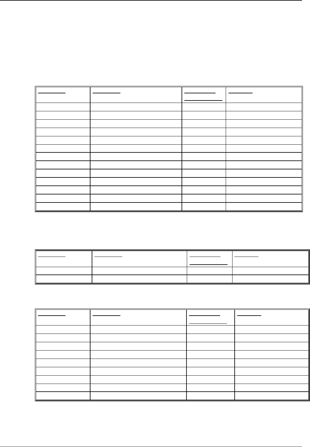
PT 5780 DVB-T Modulator ProTelevision Technologies RS232 Communication
Instruction Manual Revision 3.11
6-25
6.3 Commands Summary
All commands listed consist of both a set and request command unless specifically listed in the
table.
6.3.1 Mandated Commands
Command Parameter Status after
Factory Reset Remarks
*CLS
*ESE No action
*ESE? No action
*ESR? No action
*IDN?
*OPC No action
*OPC? No action
*RST
*SRE No action
*SRE? No action
*STB? No action
*TST? No action
*WAI No action
6.3.2 Required commands
6.3.2.1 SYSTem subsystem
Command Parameter Status after
Factory Reset
Remarks
:ERRor? Query only
:VERSion? Query only
6.3.2.2 STATus subsystem
Command Parameter Status after
Factory Reset
Remarks
:OPERation
[:EVENt]? Query only. No action
:CONDition? Query only. No action
:ENABle 0 to 65535 No action
:QUEStion
[:EVENt]? Query only. No action
:CONDition? Query only. No action
:ENABle No action
:PRESet No action

RS232 Communication ProTelevision Technologies PT 5780 DVB-T Modulator
Instruction Manual Revision 3.11 6-26
6.3.3 Instrument commands
6.3.3.1 DIAGnostic subsystem
Command Parameter Status after
Factory Reset
Remarks
:DISPlay - No query. No action
:ERRorqueue? - - Query only. No action
:ERRorqueue
:RESet - - No query. No action
6.3.3.2 SYSTem subsystem
6.3.3.3 USER subsystem
Command Parameter Status after
Factory Reset
Remarks
:NAMe <”Name”> String data
6.3.3.4 DISPlay subsystem
Command Parameter Status after
Factory Reset
Remarks
:CONTrast 0 to 100 % 25
Command Parameter Status after
Factory Reset Remarks
:PRESet
[:RECall] 1 to 10 -
:STORe 1 to 10 - No query.
:NAMe 1 to 10,<”Name”> - Name – string data
format. Query command
format is
:PRES:NAME? <System
Preset No. 1 to 10>.
:DATE <YYYY,MM,D> 2002,01,01
:TIME <HH,MM,SS> 00,00,00
:OINStalled <”xxxx.xxxx.xxxx.xxxx”> String data format
:OUSed <”101001….”> String data format
consisting of 1’s and 0’s
:COMMunicate:
SERial:TRANsmit
:BAUD
<Port no.>,<Baudrate>
1 | 2 ,
1200 | 2400 | 4800 | 9600 |
19200 | 115200
On both ports -
19200
:FRES See Chap. 4.4 No query.

PT 5780 DVB-T Modulator ProTelevision Technologies RS232 Communication
Instruction Manual Revision 3.11
6-27
6.3.3.5 INPut subsystem
Command Parameter Status after
Factory Reset
Remarks
:ASWitch OFF | ON OFF
:PRImary <high priority>, <low priority>
(low priority only useful in
hierarchical version of modulator)
A | B | C | D | DEModulator
High priority =
A
Low priority = B
The low priority input
parameter should be
ignored in a non-
hierarchical modulator.
:SECondary <high priority>, <low priority>
(low priority only useful if
hierarchical version of modulator)
A | B | C | D | DEModulator
High priority =
B
Low priority = A
The low priority input
parameter should be
ignored in a non-
hierarchical modulator.
:REFerence
:SOURce ADETect | EXTernal | INTernal ADET
:PPS HIMPedance | O_50 HIMP
:MHZ HIMPedance | O_50 O_50
:PPSTlevel 0 to 3.5 V 3.5 V
:REFerence? Query only
:INPut:BUFFerfill?
or
:INPut:BUFFerfill:
HP?
Query only
:INPut:BUFFerfill:
LP?
Low priority in an
hierarchical system.
Query only
:TXIDent 0 to 65535 0 Only available in SFN-
version
6.3.3.6 OUTPut subsystem
Command Parameter Status after
Factory Reset
Remarks
:MODE
:HIERarchy NONE | H_1 | H_2 | H_4 NONE Only available in
Hierarchical version
:IFFT F2K | F8K F8K
:CODerate R1_2 | R2_3 | R3_4 | R5_6 |
R7_8
R2_3 High Priority Code Rate
in the Hierarchical
version.
:LPCoderat
e R1_2 | R2_3 | R3_4 | R5_6 |
R7_8 R2_3 Only available in
Hierarchical version
:CONStell QPSK | QAM16 | QAM64 QAM64
:GUARd G1_4 | G1_8 | G1_16 | G1_32 G1_8
:TSENable OFF | ON OFF in non-
SFN version.
ON in SFN
version.
Only available in SFN
version
:MODE? - - Query only

RS232 Communication ProTelevision Technologies PT 5780 DVB-T Modulator
Instruction Manual Revision 3.11 6-28
Command Parameter Status after
Factory Reset
Remarks
:IF
:FREQuency 35 to 37 MHz 36 MHz Only in IF version. Step
size of 1Hz. Query only
in RF version.
:LEVel -2.0 to 8.0 dB 0.0 Only in IF version. Step
size of 0.1dB. Query only
in RF version.
:RF
:FREQuency 30 to 1000 MHz 474 MHz Only in RF version. Step
size of 1Hz.
:LEVel -10.0 to 0.0 dB 0.0 Only in RF version. Step
size of 0.1dB.
:FREQuency 35 to 37MHz
(if IF version)
30 to 1000 MHz
(if RF version)
36 MHz
(if IF version)
474 MHz
(if RF version)
:LEVel -2.0 to 8.0 dB
(if IF Version)
-10.0 to 0.0 dB
(if RF version)
0.0
:BANDwidth 6 | 7 | 8 MHz 8
:CRASter IUHF | IVHF | IUVH |
UCH (short form)
IUHF | IVHF | IUVHF |
UCHANNEL (long form)
IUHF Only in RF version. The
corresponding query
replies are: IUHF | IVHF |
IUVHF | UCHANNEL
:VSUB VHFB | VHFL | VHFI VHFB Only in RF version and
VHF raster is selected.
:UCDefinition <Start channel>,
<Base frequency>
Start = 21,
Base freq =
470 MHz
Only in RF version and
user defined raster is
selected.
:CHANnel Dependent on channel raster:
IUHF: 21 to 69 |
IVHF & VHF(L): 0 to 5 |
IVHF & VHF(B): 5 to 12 |
IVHF & VHF(I): 1 to 6 |
UCH: 0 to 99
21 (ITU UHF) Only in RF version.
:WINDow? Query only
[:ENABle] OFF | ON ON
:ROLLoff W1_64 | W1_128 | W1_256 |
W1_512
W1_64
:POLarity NORMal | INVerted NORMal
:PEAK
:CLIPping -10.0 to 0.0 dB 0.0 Steps of +0.5dB

PT 5780 DVB-T Modulator ProTelevision Technologies RS232 Communication
Instruction Manual Revision 3.11
6-29
6.3.3.7 MONitor subsystem
Command Parameter Status after
Factory Reset
Remarks
:SOURce HPIN | LPIN | HPOUT | LPOUT |
TPICture | DEModulator
HPIN
6.3.3.8 PRECorrect (Nonlinear Pre-corrector) subsystem
Command Parameter Status after
Factory Reset
Remarks
:ENABle OFF | ON OFF
:GAIN -3.0 to 3.0 dB 0.0 Steps of 0.2 dB
:POINt 0 to 255, {<real>, <imag>} Query command format
is :PREC:POIN? <Point
No>
:CURVe {<real>,<imag>}
:DESCription <”Curve Description”> Curve Description is in
string data format.
:USERpoints <”User Point Information”> User Point Information is
in string data format.
:CURVe
:PRESet
<Preset No. 1 to 10>,
<”Curve Description”>,
<Pre-corrector Gain>,
<Clip Level>,
<”User point information”>,
{<real>,<imag>}
Query command format
is :PREC:CURV:PRES?
<Preset No. 1 to 10>.
:CURVe
:CHECksum?
0 to 10 Query only. Note curve
‘0’ indicates the “active”
location.
:CURVe
:RECall
1 to 10
6.3.3.9 LPRecorrect (Linear Pre-corrector) subsystem
Command Parameter Status after
Factory Reset
Remarks
:ENABle OFF | ON OFF
:COEFFicients {<real>,<imag>}
:DESCription <”Coefficient Description”> Coefficient Description is
in string data format.
:USERpoints <”User Point Information”> User Point Information is
in string data format.
:CHECksum? 0 to 10 Query only. “0” indicates
the “active” location.
:PRESet 1 to 10,
<”Coefficient Description”>,
<”User Point Information”,
{<real>,<imag>}
Query command format
is LPR:PRES? <Preset
No. 1 to 10>
:RECall 1 to 10

RS232 Communication ProTelevision Technologies PT 5780 DVB-T Modulator
Instruction Manual Revision 3.11 6-30
6.3.3.10 SFN subsystem
Command Parameter Status after
Factory Reset
Remarks
:DEL -1 to 1 sec 0 In 100ns steps.
:MARGin? Or
:MARGin:HP? Query only. Response in
msecs.
:MARGin:LP? Query only. Response in
msecs.
:MAXDelay? Query only.
:OPTional
:TIMeoffset? Query only.
:FREQoffset? Query only.
:POWer? Query only.
:MIPData OFF | ON,1 | ON,2 OFF Query command
provides serial port no. to
which MIP data is output.
If “port no.” is 0, MIP data
output is not active.
6.3.3.11 ALARm subsystem
Command Parameter Status after
Factory Reset
Remarks
:SDEFinition <alarm condition>, <”alarm
destination ”>
0 to 13,
any combination of “M12E”
If “alarm condition” = 0,
definition applies to all
alarm condition.
M – Mute control
1 to 2 – Relays 1 to 2
E – Event Log
:STATus? 1 to 13 Query only. Response
format is:
<Alarm ID No(1 to 12)>,
<Is alarm active? (1,0)>,
<Alarm counter, i.e.
number of times alarm
has been raised since
last counter reset or
power on>
CRESet 0 to 13 No query.
0 - resets all alarm
counters.

PT 5780 DVB-T Modulator ProTelevision Technologies RS232 Communication
Instruction Manual Revision 3.11
6-31
6.3.3.12 EVENt subsystem
Command Parameter Status after
Factory Reset
Remarks
:COUNt? Query only. Response
format is:
<n>
n : total number of events
recorded in the log
:CLEAr No Query. Clears the
entire event log.
:VIEW? n
n = 0 to max event count
Query only. Response
format is:
<id number, “tds”, “info”>
id number : identification
number for the recorded
event type
tds: time and date stamp
for the event in the
format “yyyy-mm-dd,
hh:mm:ss”
info: Supplementary text
string describing the
event type
6.3.3.13 TEST subsystem
Command Parameter Status after
Factory Reset
Remarks
:ENABle OFF | SCARrier | M1Carrier |
M50Carrier | TSSTuffing
OFF
:M1Carrier 1 to 1705 1 -1 carrier in 2k mode.
1 to 6817 1 -1 carrier in 8k mode.
:M50Carrier 1 to 1705 1 -50 carrier in 2k mode.
1 to 6817 1 -50 carrier in 8k mode.
6.3.3.14 FACTory subsystem
Command Parameter Status after
Factory Reset Remarks
:SNINst? <Instrument Serial No>
:SNXAcboard? <XA Serial No>
:MONitor
:LIMits?
“MC_BT” | “MC_025V” |
“MC_033V” | “MC_050V” |
“MC_120V” ,
<lower limit>,
<upper limit>
Format for query
command:
:FACT:MON:LIM?
“MC_BT”
:MONitor
:CURRent?
“MC_BT” | “MC_025V” |
“MC_033V” | “MC_050V” |
“MC_120V”
Query only.

RS232 Communication ProTelevision Technologies PT 5780 DVB-T Modulator
Instruction Manual Revision 3.11 6-32
6.4 Error Codes
6.4.1 Command errors [-199, -100]
Error
Number
Error string
[description/explanation/example]
-100 Command error
The command is invalid or incorrect.
-101 Invalid character
A command or parameter contains an invalid character, e.g. a header containing an
ampersand, SYST:VERS&.
-102 Syntax error
An unrecognised command or data type was encountered, e.g. a string was received
when the generator did not accept strings.
-103 Invalid separator
A separator was expected, but an illegal character was encountered, e.g. the
semicolon was omitted after a command, *IDN?:SYST:ERR?;
-104 Data type error
A data element different than one allowed was encountered, e.g. numeric data was
expected but string data was encountered.
-108 Parameter not allowed
More parameters was received than expected for the command, e.g. the *IDN?;
command accepts no parameters, so receiving *IDN? 2; is not allowed
-109 Missing parameter
Fewer parameters were received than expected for the command.
-110 Command header error
An error was detected in the command header.
-111 Header separator error
A character which is not a legal header separator was encountered, e.g. no white
space followed the header, thus SYST:PRES:NAME”MACRO” is an error.
-112 Program mnemonic too long
The header contains more than twelve characters.
-113 Undefined header
The header is syntactically correct, but is not defined for the device.
-114 Header suffix out of range
The command is invalid because the value of the numeric suffix attached to the
program mnemonic is out of range, e.g. OUTP:ALAR3? is illegal because only 2 alarm
outputs exists.
-120 Numeric data error
An error in the numeric data was encountered.
-121 Invalid character in number
An invalid character for the data type was encountered, e.g. an alpha in a decimal
value.
-123 Exponent too large
The magnitude of the exponent was larger than 32000.
-124 Too many digits
The mantissa of a decimal numeric data element contained more than 255 digits.
-125 Numeric data not allowed
A legal numeric data was received, but the device does not accept one.
-130 Suffix error
An error in the suffix was encountered.

PT 5780 DVB-T Modulator ProTelevision Technologies RS232 Communication
Instruction Manual Revision 3.11
6-33
Error
Number
Error string
[description/explanation/example]
-131 Invalid suffix
The suffix is syntactically incorrect.
-134 Suffix too long
The suffix contains more than twelve characters.
-138 Suffix not allowed
A suffix was encountered after a numeric element that does not allow suffixes.
-140 Character data error
An error in the character was encountered.
-150 String data error
An error in the string data was encountered.
-151 Invalid string data
A string data element was expected, but was invalid for some reason, e.g. an END
message was received before the terminal quote character.
-158 String data not allowed
A string data element was received but was not allowed by the device.
-160 Block data error
There is an error in the block data received.
-161 Invalid block data
A block data was expected, but was invalid for some reason.
-170 Expression error
There is an error in the expression received.
6.4.2 Execution errors [-299, -200]
Error
Number
Error string
[Description/explanation/example]
-200 Execution error
-203 Command Protected
Indicates that a legal protected program command or query could not be executed
because the command was disabled.
-220 Parameter error
Indicates that a program data element related error occurred.
-222 Data out of range
Indicates that a legal program data element was received but could not be executed
because the interpreted values was outside the range as defined by the device, e.g.
the command OUTP:GAIN 5; is illegal since the gain cannot exceed 3 dB.
-223 Too much data
Indicates that a legal program data element of block, expression, or string type was
received that contained more data than the device could handle due to memory or
related device-specific requirements.
-224 Illegal parameter value
Used where exact value, from a list of possible, was expected.
-233 Invalid version
Indicates that a legal program data element was parsed but could not be executed
because the version of the data is incorrect to the device.

ProTelevision Technologies PT 5780 DVB-T Modulator
Instruction Manual Revision 3.11 6-34
Error
Number
Error string
[Description/explanation/example]
-241 Hardware missing
Indicates that a legal program command or query could not be executed because of
missing device hardware.
6.4.3 Device specific errors [-399, -300]
Error
Number Error string
[Description/explanation/example]
-300 Device-specific error
-350 Queue overflow
A specific code entered into the queue in lieu of the code that caused the error. This
code indicates that there is no room in the queue and an error occurred but was not
recorded.
-360 Communication error
A communication error on the serial port was detected
-361 Parity error in program message
Parity bit not correct when data received on the serial port
-362 Framing error in program message
A stop bit was not detected when data was received, e.g. a bad rate mismatch.
-363 Input buffer overrun
Software or hardware input buffer on serial port overflows.
6.4.4 Query errors [-499, -400]
Error
Number
Error string
[Description/explanation/example]
-400 Query error
An error occurred during a query.
-410 Query INTERRUPTED
Indicates that a condition causing an INTERRUPTED Query error occurred.
-420 Query UNTERMINATED
Indicates that a condition causing an UNTERMINATED Query error occurred.
-430 Query DEADLOCKED
Indicates that a condition causing an DEADLOCKED Query error occurred.
6.4.5 Device specific errors [1, 32468]
None.

PT 5780 DVB-T Modulator ProTelevision Technologies
Instruction Manual Revision 3.11
A-1
Appendix A Menu System Maps
A set of charts describing the menu system is provided attached overleaf in order to
diagrammatically show the structure of the menu system and the various menu options and
parameters. The charts enclosed are:
• Status Menu System
• Configuration Menu System (page 1 of 2)
• Configuration Menu System (page 2 of 2)
All menu windows in the menu system contain a four-digit number in the top right hand position.
This number is known as the menu identification number and is useful for referencing and
navigating purposes and is shown in “bold” in the Menu System Charts. The menu-structure
has a maximum of four levels; hence the four-digit identification.

PT 5780 DVB-T Modulator ProTelevision Technologies
Instruction Manual Revision 3.11
A-2
Appendix B Document History
Rev.: Date: Name: Details:
1.0 280801 DG First version of manual.
1.1 181001 DG Amendments made to reflect changes made in
software from software version 1.01 to software
version 1.1.
2.0 301101 DG Amendments made to reflect changes made in
software from software version 1.1 to software
version 2.0.
3.0 30.01.2003 HSO Amendments made to reflect changes to the menu
structure and introduction of new features (event log).
This update only applies to modulator units based on
ASIC technology. SW release 3.02
3.1 13.03.2003 HSO Selection of SPI LVDS input via “C” input.
UBS logo and text references substituted for
ProTelevision logo and text references.
3.11
25.08.2003
HSO
3.6.1: RS232 wiring schemes updated (handshake
not implemented).
4.2.1: Presentation method for useful ASI data on the
monitor output described.