UBS Axcera LU1000AT 1000-Watt UHF Transmitter User Manual 379378
UBS-Axcera 1000-Watt UHF Transmitter 379378
Contents
- 1. Title Page Exciter
- 2. Table of Contents Exciter
- 3. Chapter 1 Exciter
- 4. Chapter 2 Exciter
- 5. Chapter 3 Exciter
- 6. Chapter 4 Exciter
- 7. Chapter 5 Exciter
- 8. Appendix Pages Exciter
- 9. Data Sheet Exciter and Amplifier
- 10. Drawings List Exciter
- 11. Title Page External Amplifier
- 12. Table of Contents External Amplifier
- 13. Chapter 1 External Amplifier
- 14. Chapter 2 External Amplifier
- 15. Chapter 3 External Amplifier
- 16. Chapter 4 External Amplifier
- 17. Chapter 5 External Amplifier
- 18. Appendix Pages External Amplifier
- 19. Drawings List External Amplifier
Chapter 1 Exciter

UHF Analog Driver/Transmitter Chapter 1, Introduction
LX Series, Rev. 0 1-1
Chapter 1
Introduction
This manual explains the installation,
setup, alignment, and maintenance
procedures for the Innovator LX Series
UHF analog modular driver/transmitter.
It is important that you read all of the
instructions, especially the safety
information in this chapter, before you
begin to install or operate the unit.
1.1 Manual Overview
This instruction manual is divided into
five chapters and supporting appendices.
Chapter 1, Introduction, contains
information on the assembly numbering
system used in the manual, safety,
maintenance, return procedures, and
warranties. The second chapter describes
the driver/transmitter and includes
discussions on system control and status
indicators and remote control
connections. Chapter 3 explains how to
unpack, install, setup, and operate the
driver/transmitter. Chapter 4 contains
circuit-level descriptions for boards and
board-level components in the
driver/transmitter. Chapter 5, Detailed
Alignment Procedures, provides
information on adjusting the system
assemblies for optimal operation. The
appendices contain assembly and
subassembly drawings and parts lists,
and system specifications.
1.2 Assembly Designators
Axcera has assigned assembly numbers,
such as Ax (x=1,2,3…), to all assemblies,
modules, and boards that are referenced
in the text of this manual and shown on
the block diagrams and interconnect
drawings provided in the appendices.
These supporting documents are
arranged in increasing numerical order in
the appendices. Section titles in the text
for assembly or module descriptions or
alignment procedures contain the
associated part number(s) and the
relevant appendix that contains the
drawings for that item.
1.3 Safety
The UHF drivers and transmitters
manufactured by Axcera are designed to
be easy to use and repair while providing
protection from electrical and mechanical
hazards. Listed throughout the manual
are notes, cautions, and warnings
concerning possible safety hazards that
may be encountered while operating or
servicing the driver/transmitter. Please
review these warnings and familiarize
yourself with the operation and servicing
procedures before working on the
driver/transmitter.
Read All Instructions – All of the
operating and safety instructions should
be read and understood before operating
this equipment.
Retain Manuals – The manuals for the
driver/transmitter should be retained at
the transmitter site for future reference.
We provide two sets of manuals for this
purpose; one set can be left at the office
while one set can be kept at the site.
Heed all Notes, Warnings, and
Cautions – All of the notes, warnings,
and cautions listed in this safety section
and throughout the manual must be
followed.
Follow Instructions – All of the
operating and use instructions for the
driver/transmitter should be followed.
Cleaning – Unplug or otherwise
disconnect all power from the equipment
before cleaning. Do not use liquid or
aerosol cleaners. Use a damp cloth for
cleaning.
Ventilation – Openings in the cabinets
and module front panels are provided for

UHF Analog Driver/Transmitter Chapter 1, Introduction
LX Series, Rev. 0 1-2
ventilation. To ensure the reliable
operation of the driver/transmitter, and
to protect the unit from overheating,
these openings must not be blocked.
Servicing – Do not attempt to service
this product yourself until becoming
familiar with the equipment. If in doubt,
refer all servicing questions to qualified
Axcera service personnel.
Replacement Parts – When
replacement parts are used, be sure that
the parts have the same functional and
performance characteristics as the
original part. Unauthorized substitutions
may result in fire, electric shock, or other
hazards. Please contact the Axcera
Technical Service Department if you have
any questions regarding service or
replacement parts.
1.4 Maintenance
The Innovator LX Series
Driver/Transmitter is designed with
components that require little or no
periodic maintenance except for the
routine cleaning of the fans and the front
panels of the modules.
The amount of time between cleanings
depends on the conditions within the
transmitter room. While the electronics
have been designed to function even if
covered with dust, a heavy buildup of
dust, dirt, or insects will affect the
cooling of the components. This could
lead to a thermal shutdown or the
premature failure of the affected module.
When the front panels of the modules
become dust covered, the top covers
should be taken off and any accumulated
foreign material should be removed. A
vacuum cleaner, utilizing a small, wand-
type attachment, is an excellent way to
suction out the dirt. Alcohol and other
cleaning agents should not be used
unless you are certain that the solvents
will not damage components or the silk-
screened markings on the modules and
boards. Water-based cleaners can be
used, but do not saturate the
components. The fans and heatsinks
should be cleaned of all dust or dirt to
permit the free flow of air for cooling
purposes.
It is recommended that the operating
parameters of the driver/transmitter be
recorded from the LEDs on the modules
and the LCD system metering on the
control/monitoring module at least once
a month. It is suggested that this data be
retained in a rugged folder or envelope.
1.5 Material Return Procedure
To insure the efficient handling of
equipment or components that have been
returned for repair, Axcera requests that
each returned item be accompanied by a
Material Return Authorization Number
(MRA#).
An MRA# can be obtained from any
Axcera Field Service Engineer by
contacting the Axcera Field Service
Department at (724) 873-8100 or by fax
at (724) 873-8105. This procedure
applies to all items sent to the Field
Service Department regardless of
whether the item was originally
manufactured by Axcera.
When equipment is sent to the field on
loan, an MRA# is included with the unit.
The MRA# is intended to be used when
the unit is returned to Axcera. In
addition, all shipping material should be
retained for the return of the unit to
Axcera.
Replacement assemblies are also sent
with an MRA# to allow for the proper
routing of the exchanged hardware.
Failure to close out this type of MRA# will
normally result in the customer being
invoiced for the value of the loaner item
or the exchange assembly.
When shipping an item to Axcera, please
include the MRA# on the packing list and
on the shipping container. The packing
slip should also include contact

UHF Analog Driver/Transmitter Chapter 1, Introduction
LX Series, Rev. 0 1-3
information and a brief description of why
the unit is being returned.
Please forward all MRA items to:
AXCERA, LLC
103 Freedom Drive
P.O. Box 525
Lawrence, PA 15055-0525 USA
For more information concerning this
procedure, call the Axcera Field Service
Department.
Axcera can also be contacted through e-
mail at info@axcera.com and on the
Web at www.axcera.com.
1.6 Limited One-Year Warranty for
Axcera Products
Axcera warrants each new product that
it has manufactured and sold against
defects in material and workmanship
under normal use and service for a
period of one (1) year from the date of
shipment from Axcera's plant, when
operated in accordance with Axcera's
operating instructions. This warranty
shall not apply to tubes, fuses,
batteries, or bulbs.
Warranties are valid only when and if
(a) Axcera receives prompt written
notice of breach within the period of
warranty, (b) the defective product is
properly packed and returned by the
buyer (transportation and insurance
prepaid), and (c) Axcera determines, in
its sole judgment, that the product is
defective and not subject to any misuse,
neglect, improper installation,
negligence, accident, or (unless
authorized in writing by Axcera) repair
or alteration. Axcera's exclusive liability
for any personal and/or property
damage (including direct, consequential,
or incidental) caused by the breach of
any or all warranties, shall be limited to
the following: (a) repairing or replacing
(in Axcera's sole discretion) any
defective parts free of charge (F.O.B.
Axcera’s plant) and/or (b) crediting (in
Axcera's sole discretion) all or a portion
of the purchase price to the buyer.
Equipment furnished by Axcera, but not
bearing its trade name, shall bear no
warranties other than the special hours-
of-use or other warranties extended by
or enforceable against the manufacturer
at the time of delivery to the buyer.
NO WARRANTIES, WHETHER
STATUTORY, EXPRESSED, OR
IMPLIED, AND NO WARRANTIES OF
MERCHANTABILITY, FITNESS FOR
ANY PARTICULAR PURPOSE, OR
FREEDOM FROM INFRINGEMENT,
OR THE LIKE, OTHER THAN AS
SPECIFIED IN PATENT LIABILITY
ARTICLES, AND IN THIS ARTICLE,
SHALL APPLY TO THE EQUIPMENT
FURNISHED HEREUNDER.

UHF Analog Driver/Transmitter Chapter 1, Introduction
LX Series, Rev. 0 1-4
) WARNING!!!
½ HIGH VOLTAGE ¾
DO NOT ATTEMPT TO REPAIR OR TROUBLESHOOT THIS EQUIPMENT UNLESS
YOU ARE FAMILIAR WITH ITS OPERATION AND EXPERIENCED IN
SERVICING HIGH VOLTAGE EQUIPMENT. LETHAL VOLTAGES ARE PRESENT
WHEN POWER IS APPLIED TO THIS SYSTEM. IF POSSIBLE, TURN OFF
POWER BEFORE MAKING ADJUSTMENTS TO THE SYSTEM.
RADIO FREQUENCY RADIATION HAZARD
MICROWAVE, RF AMPLIFIERS AND TUBES GENERATE HAZARDOUS RF
RADIATION THAT CAN CAUSE SEVERE INJURY INCLUDING CATARACTS,
WHICH CAN RESULT IN BLINDNESS. SOME CARDIAC PACEMAKERS MAY BE
AFFECTED BY THE RF ENERGY EMITTED BY RF AND MICROWAVE
AMPLIFIERS. NEVER OPERATE THE TRANSMITTER SYSTEM WITHOUT A
PROPERLY MATCHED RF ENERGY ABSORBING LOAD ATTACHED. KEEP
PERSONNEL AWAY FROM OPEN WAVEGUIDES AND ANTENNAS. NEVER LOOK
INTO AN OPEN WAVEGUIDE OR ANTENNA. MONITOR ALL PARTS OF THE RF
SYSTEM FOR RADIATION LEAKAGE AT REGULAR INTERVALS.

UHF Analog Driver/Transmitter Chapter 1, Introduction
LX Series, Rev. 0 1-5
EMERGENCY FIRST AID INSTRUCTIONS
Personnel engaged in the installation, operation, or maintenance of this equipment are urged to become
familiar with the following rules both in theory and practice. It is the duty of all operating personnel to be
prepared to give adequate Emergency First Aid and thereby prevent avoidable loss of life.
RESCUE BREATHING
1. Find out if the person is
breathing.
You must find out if the person
has stopped breathing. If you
think he is not breathing, place
him flat on his back. Put your ear
close to his mouth and look at his
chest. If he is breathing you can
feel the air on your cheek. You
can see his chest move up and
down. If you do not feel the air
or see the chest move, he is not
breathing.
2. If he is not breathing, open
the airway by tilting his head
backwards.
Lift up his neck with one hand
and push down on his forehead
with the other. This opens the
airway. Sometimes doing this will
let the person breathe again by
himself.
3. If he is still not breathing,
begin rescue breathing.
-Keep his head tilted backward.
Pinch nose shut.
-Put your mouth tightly over his
mouth.
-Blow into his mouth once every
five seconds
-DO NOT STOP rescue breathing
until help arrives.
LOOSEN CLOTHING - KEEP
WARM
Do this when the victim is
breathing by himself or help is
available. Keep him as quiet as
possible and from becoming
chilled. Otherwise treat him for
shock.
BURNS
SKIN REDDENED: Apply ice cold water to burned
area to prevent burn from going deeper into skin
tissue. Cover area with clean sheet or cloth to keep
away air. Consult a physician.
SKIN BLISTERED OR FLESH CHARRED: Apply ice
cold water to burned area to prevent burn from
going deeper into skin tissue.
Cover area with clean sheet or cloth to keep away
air. Treat victim for shock and take to hospital.
EXTENSIVE BURN - SKIN BROKEN: Cover area with
clean sheet or cloth to keep away air. Treat victim
for shock and take to hospital.

UHF Analog Driver/Transmitter Chapter 1, Introduction
LX Series, Rev. 0 1-6
Note: Because of possible FCC assigned offset, check for the assigned Carrier
Frequency as written on License.
UHF Channels NTSC Standard IF, 45.75 MHz
Visual Carrier Frequency (MHz) L.O.
(MHz) Crystal Frequency (MHz)
Channel Nominal Minus Plus Nominal Nominal Minus Plus
14 471.25 471.24 471.26 517.00 64.625 64.62375 64.62625
15 477.25 477.24 477.26 523.00 65.375 65.37375 65.37625
16 483.25 483.24 483.26 529.00 66.125 66.12375 66.12625
17 489.25 489.24 489.26 535.00 66.875 66.87375 66.87625
18 495.25 495.24 495.26 541.00 67.625 67.62375 67.62625
19 501.25 501.24 501.26 547.00 68.375 68.37375 68.37625
20 507.25 507.24 507.26 553.00 69.125 69.12375 69.12625
21 513.25 513.24 513.26 559.00 69.875 69.87375 69.87625
22 519.25 519.24 519.26 565.00 70.625 70.62375 70.62625
23 525.25 525.24 525.26 571.00 71.375 71.37375 71.37625
24 531.25 531.24 531.26 577.00 72.125 72.12375 72.12625
25 537.25 537.24 537.26 583.00 72.875 72.87375 72.87625
26 543.25 543.24 543.26 589.00 73.625 73.62375 73.62625
27 549.25 549.24 549.26 595.00 74.375 74.37375 74.37625
28 555.25 555.24 555.26 601.00 75.125 75.12375 75.12625
29 561.25 561.24 561.26 607.00 75.875 75.87375 75.87625
30 567.25 567.24 567.26 613.00 76.625 76.62375 76.62625
31 573.25 573.24 573.26 619.00 77.375 77.37375 77.37625
32 579.25 579.24 579.26 625.00 78.125 78.12375 78.12625
33 585.25 585.24 585.26 631.00 78.875 78.87375 78.87625
34 591.25 591.24 591.26 637.00 79.625 79.62375 79.62625
35 597.25 597.24 597.26 643.00 80.375 80.37375 80.37625
36 603.25 603.24 603.26 649.00 81.125 81.12375 81.12625
37 609.25 609.24 609.26 655.00 81.875 81.87375 81.87625
38 615.25 615.24 615.26 661.00 82.625 82.62375 82.62625
39 621.25 621.24 621.26 667.00 83.375 83.37375 83.37625
40 627.25 627.24 627.26 673.00 84.125 84.12375 84.12625
41 633.25 633.24 633.26 679.00 84.875 84.87375 84.87625
42 639.25 639.24 639.26 685.00 85.625 85.62375 85.62625
43 645.25 645.24 645.26 691.00 86.375 86.37375 86.37625

UHF Analog Driver/Transmitter Chapter 1, Introduction
LX Series, Rev. 0 1-7
Note: Because of possible FCC assigned offset, check for the assigned Carrier
Frequency as written on License.
UHF Channels NTSC Standard IF, 45.75 MHz
Visual Carrier Frequency (MHz) L.O.
(MHz) Crystal Frequency (MHz)
Channel Nominal Minus Plus Nominal Nominal Minus Plus
44 651.25 651.24 651.26 697.00 87.125 87.12375 87.12625
45 657.25 657.24 657.26 703.00 87.875 87.87375 87.87625
46 663.25 663.24 663.26 709.00 88.625 88.62375 88.62625
47 669.25 669.24 669.26 715.00 89.375 89.37375 89.37625
48 675.25 675.24 675.26 721.00 90.125 90.12375 90.12625
49 681.25 681.24 681.26 727.00 90.875 90.87375 90.87625
50 687.25 687.24 687.26 733.00 91.625 91.62375 91.62625
51 693.25 693.24 693.26 739.00 92.375 92.37375 92.37625
52 699.25 699.24 699.26 745.00 93.125 93.12375 93.12625
53 705.25 705.24 705.26 751.00 93.875 93.87375 93.87625
54 711.25 711.24 711.26 757.00 94.625 94.62375 94.62625
55 717.25 717.24 717.26 763.00 95.375 95.37375 95.37625
56 723.25 723.24 723.26 769.00 96.125 96.12375 96.12625
57 729.25 729.24 729.26 775.00 96.875 96.87375 96.87625
58 735.25 735.24 735.26 781.00 97.625 97.62375 97.62625
59 741.25 741.24 741.26 787.00 98.375 98.37375 98.37625
60 747.25 747.24 747.26 793.00 99.125 99.12375 99.12625
61 753.25 753.24 753.26 799.00 99.875 99.87375 99.87625
62 759.25 759.24 759.26 805.00 100.625 100.62375 100.62625
63 765.25 765.24 765.26 811.00 101.375 101.37375 101.37625
64 771.25 771.24 771.26 817.00 102.125 102.12375 102.12625
65 777.25 777.24 777.26 823.00 102.875 102.87375 102.87625
66 783.25 783.24 783.26 829.00 103.625 103.62375 103.62625
67 789.25 789.24 789.26 835.00 104.375 104.37375 104.37625
68 795.25 795.24 795.26 841.00 105.125 105.12375 105.12625
69 801.25 801.24 801.26 847.00 105.875 105.87375 105.87625
70 807.25 807.24 807.26 853.00 106.625 106.62375 106.62625

UHF Analog Driver/Transmitter Chapter 1, Introduction
LX Series, Rev. 0 1-8
Note: Because of possible FCC assigned offset, check for the assigned Carrier
Frequency as written on License.
UHF Frequency Assignments
Channel
Number
Bandwidth
(MHz)
Video
(MHz)
Color
(MHz)
Audio
(MHz)
14 470-476 471.25 474.83 475.75
15 476-482 477.25 480.83 481.75
16 482-488 483.25 486.83 487.75
17 488-494 489.25 492.83 493.75
18 494-500 495.25 498.83 499.75
19 500-506 501.25 504.83 505.75
20 506-512 507.25 510.83 511.75
21 512-518 513.25 516.83 517.75
22 518-524 519.25 522.83 523.75
23 524-530 525.25 528.83 529.75
24 530-536 531.25 534.83 535.75
25 536-542 537.25 540.83 541.75
26 542-548 543.25 546.83 547.75
27 548-554 549.25 552.83 553.75
28 554-560 555.25 558.83 559.75
29 560-566 561.25 564.83 565.75
30 566-572 567.25 570.83 571.75
31 572-578 573.25 576.83 577.75
32 578-584 579.25 582.83 583.75
33 584-590 585.25 588.83 589.75
34 590-596 591.25 594.83 595.75
35 596-602 597.25 600.83 601.75
36 602-608 603.25 606.83 607.75
37 608-614 609.25 612.83 613.75
38 614-620 615.25 618.83 619.75
39 620-626 621.25 624.83 625.75
40 626-632 627.25 630.83 631.75
41 632-638 633.25 636.83 637.75
42 638-644 639.25 642.83 643.75
43 644-650 645.25 648.83 649.75

UHF Analog Driver/Transmitter Chapter 1, Introduction
LX Series, Rev. 0 1-9
Note: Because of possible FCC assigned offset, check for the assigned
Carrier Frequency as written on License.
UHF Frequency Assignments
Channel
Number
Bandwidth
(MHz)
Video
(MHz)
Color
(MHz)
Audio
(MHz)
44 650-656 651.25 654.83 655.75
45 656-662 657.25 660.83 661.75
46 662-668 663.25 666.83 667.75
47 668-674 669.25 672.83 673.75
48 674-680 675.25 678.83 679.75
49 680-686 681.25 684.83 685.75
50 686-692 687.25 690.83 691.75
51 692-698 693.25 696.83 697.75
52 698-704 699.25 702.83 703.75
53 704-710 705.25 708.83 709.75
54 710-716 711.25 714.83 715.75
55 716-722 717.25 720.83 721.75
56 722-728 723.25 726.83 727.75
57 728-734 729.25 732.83 733.75
58 734-740 735.25 738.83 739.75
59 740-746 741.25 744.83 745.75
60 746-752 747.25 750.83 751.75
61 752-758 753.25 756.83 757.75
62 758-764 759.25 762.83 763.75
63 764-770 765.25 768.83 769.75
64 770-776 771.25 774.83 775.75
65 776-782 777.25 780.83 781.75
66 782-788 783.25 786.83 787.75
67 788-794 789.25 792.83 793.75
68 794-800 795.25 798.83 799.75
69 800-806 801.25 804.83 805.75
70 806-812 807.25 810.83 811.75
UHF Analog Driver/Transmitter Chapter 1, Introduction
LX Series, Rev. 0 1-10
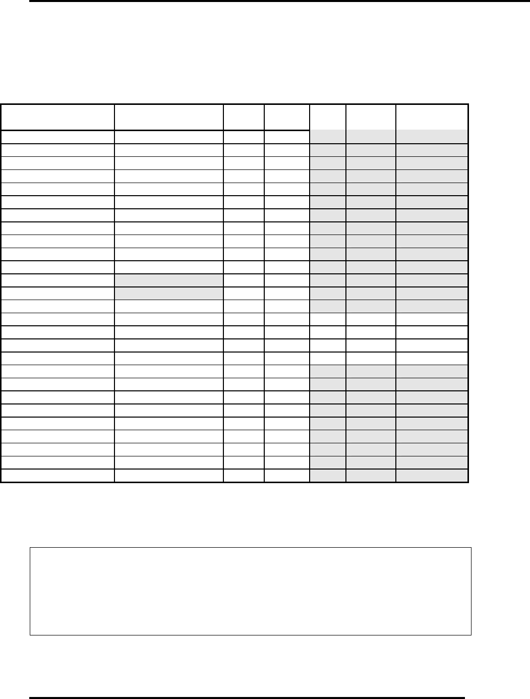
dBm, dBw, dBmV, dBµV, & VOLTAGE
EXPRESSED IN WATTS
50 Ohm System
WATTS PREFIX dBm dBw dBm
V
dBµV VOLTAGE
1,000,000,000,000 1 TERAWATT +150 +120
100,000,000,000 100 GIGAWATTS +140 +110
10,000,000,000 10 GIGAWATTS +130 +100
1,000,000,000 1 GIGAWATT +120 + 99
100,000,000 100 MEGAWATTS +110 + 80
10,000,000 10 MEGAWATTS +100 + 70
1,000,000 1 MEGAWATT + 90 + 60
100,000 100 KILOWATTS + 80 + 50
10,000 10 KILOWATTS + 70 + 40
1,000 1 KILOWATT + 60 + 30
100 1 HECTROWATT + 50 + 20
50 + 47 + 17
20 + 43 + 13
10 1 DECAWATT + 40 + 10
1 1 WATT + 30 0 + 77 +137 7.07V
0.1 1 DECIWATT + 20 - 10 + 67 +127 2.24V
0.01 1 CENTIWATT + 10 - 20 + 57 +117 0.707V
0.001 1 MILLIWATT 0 - 30 + 47 +107 224mV
0.0001 100 MICROWATTS - 10 - 40
0.00001 10 MICROWATTS - 20 - 50
0.000001 1 MICROWATT - 30 - 60
0.0000001 100 NANOWATTS - 40 - 70
0.00000001 10 NANOWATTS - 50 - 80
0.000000001 1 NANOWATT - 60 - 90
0.0000000001 100 PICOWATTS - 70 -100
0.00000000001 10 PICOWATTS - 80 -110
0.000000000001 1 PICOWATT - 90 -120
TEMPERATURE CONVERSION
°F = 32 + [(9/5) °C]
°C = [(5/9) (°F - 32)]

UHF Analog Driver/Transmitter Chapter 1, Introduction
LX Series, Rev. 0 1-11
USEFUL CONVERSION FACTORS
TO CONVERT FROM TO MULTIPLY BY
mile (US statute) kilometer (km) 1.609347
inch (in) millimeter (mm) 25.4
inch (in) centimeter (cm) 2.54
inch (in) meter (m) 0.0254
foot (ft) meter (m) 0.3048
yard (yd) meter (m) 0.9144
mile per hour (mph) kilometer per hour(km/hr) 1.60934
mile per hour (mph) meter per second (m/s) 0.44704
pound (lb) kilogram (kg) 0.4535924
gallon (gal) liter 3.7854118
U.S. liquid
(One U.S. gallon equals 0.8327 Canadian gallon)
fluid ounce (fl oz) milliliters (ml) 29.57353
British Thermal Unit watt (W) 0.2930711
per hour (Btu/hr)
horsepower (hp) watt (W) 746
NOMENCLATURE OF FREQUENCY BANDS
FREQUENCY RANGE DESIGNATION
3 to 30 kHz VLF - Very Low Frequency
30 to 300 kHz LF - Low Frequency
300 to 3000 kHz MF - Medium Frequency
3 to 30 MHz HF - High Frequency
30 to 300 MHz VHF - Very High Frequency
300 to 3000 MHz UHF - Ultrahigh Frequency
3 to 30 GHz SHF - Superhigh Frequency
30 to 300 GHz EHF - Extremely High Frequency
LETTER DESIGNATIONS FOR UPPER FREQUENCY
BANDS
LETTER FREQ. BAND
L 1000 - 2000 MHz
S 2000 - 4000 MHz
C 4000 - 8000 MHz
X 8000 - 12000 MHz
Ku 12 - 18 GHz
K 18 - 27 GHz
Ka 27 - 40 GHz
V 40 - 75 GHz
W 75 - 110 GHz

UHF Analog Driver/Transmitter Chapter 1, Introduction
LX Series, Rev. 0 1-12
ABBREVIATIONS/ACRONYMS
AC Alternating Current
AFC Automatic Frequency Control
ALC Automatic Level Control
AM Amplitude modulation
AGC Automatic Gain Control
AWG American wire gauge
BER Bit Error Rate
BW Bandwidth
DC Direct Current
D/A Digital to analog
dB Decibel
dBm Decibel referenced to 1 milliwatt
dBmV Decibel referenced to 1 millivolt
dBw Decibel referenced to 1 watt
FEC Forward Error Correction
FM Frequency modulation
Hz Hertz
ICPM Incidental Carrier Phase Modulation
I/P Input
IF Intermediate Frequency
LED Light emitting diode
LSB Lower Sideband
MPEG Motion Pictures Expert Group
O/P Output
PLL Phase Locked Loop
PCB Printed circuit board
QAM Quadrature Amplitude Modulation
UHF Analog Driver/Transmitter Chapter 1, Introduction
LX Series, Rev. 0 1-13
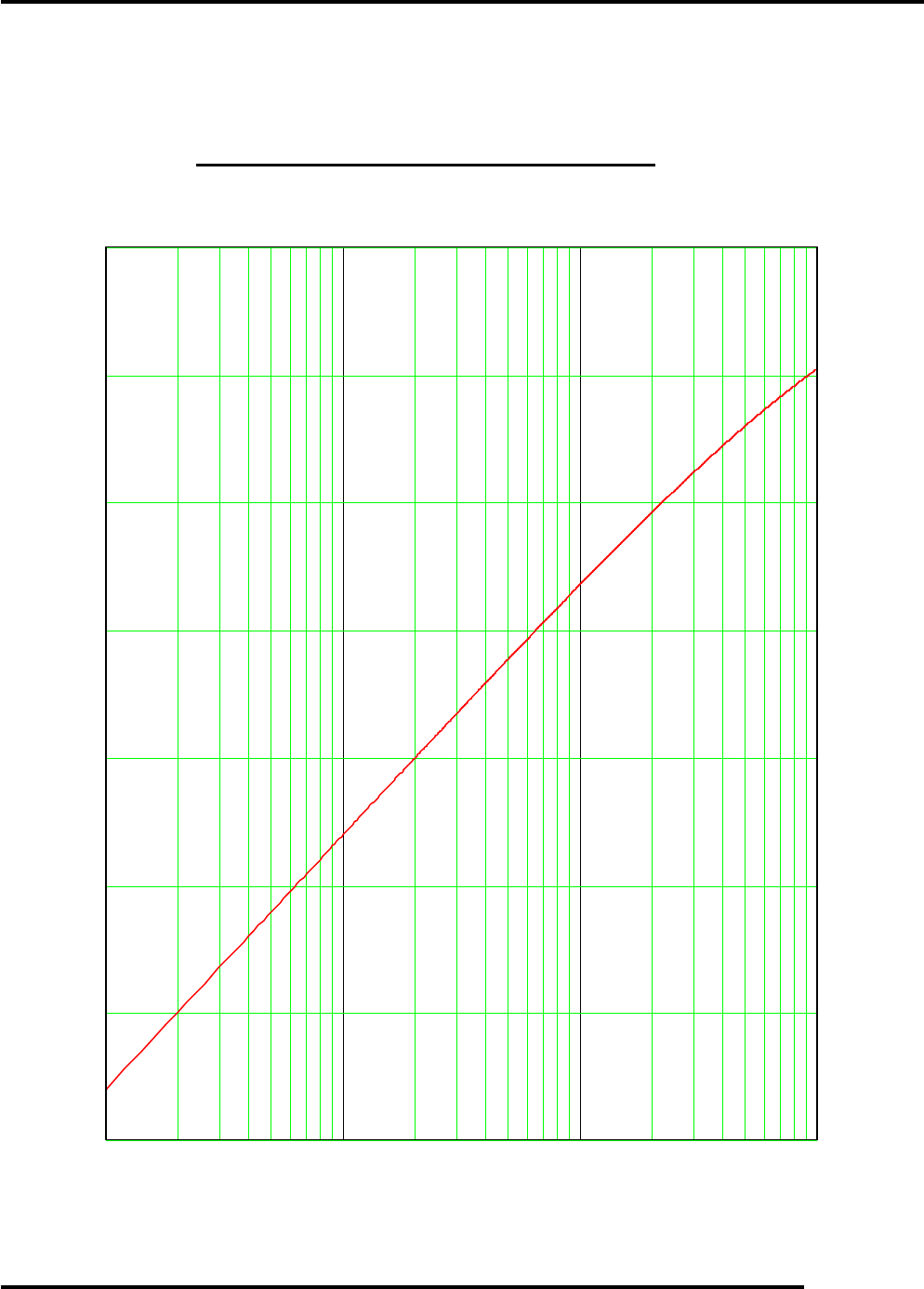
RETURN LOSS VS. VSWR
1.001 1.01 1.1 2.0
VSWR
0
-10
-20
-30
-40
-50
-60
-70
R
E
T
U
R
N
L
O
S
S
dB