UBS Axcera LU1000AT 1000-Watt UHF Transmitter User Manual 379379
UBS-Axcera 1000-Watt UHF Transmitter 379379
Contents
- 1. Title Page Exciter
- 2. Table of Contents Exciter
- 3. Chapter 1 Exciter
- 4. Chapter 2 Exciter
- 5. Chapter 3 Exciter
- 6. Chapter 4 Exciter
- 7. Chapter 5 Exciter
- 8. Appendix Pages Exciter
- 9. Data Sheet Exciter and Amplifier
- 10. Drawings List Exciter
- 11. Title Page External Amplifier
- 12. Table of Contents External Amplifier
- 13. Chapter 1 External Amplifier
- 14. Chapter 2 External Amplifier
- 15. Chapter 3 External Amplifier
- 16. Chapter 4 External Amplifier
- 17. Chapter 5 External Amplifier
- 18. Appendix Pages External Amplifier
- 19. Drawings List External Amplifier
Chapter 2 Exciter
UHF Analog Driver/Transmitter Chapter 2, System Description
& Remote Control Connections
LX Series, Rev. 0 2-1
Chapter 2
System Description & Remote Control Connections
The analog transmitters in the Innovator
LX Series are complete 10W to 100W
UHF Analog internally diplexed modular
television transmitters that operate at a
nominal visual output power of 10 to 100
watts peak sync and an average aural
output power of 1 to 10 watts, at an A/V
ratio of 10 dB, 10% sound, or .5 to 5
watts at 13 dB, 5% sound.
The LX Series can also be used as a
driver. The output power of the driver is
determined by the level needed to attain
the full output power of the transmitter.
The driver’s maximum output is 7 Watts
peak of sync.
2.1 System Overview
The Analog LX Series driver/transmitter
is made up of the modules and
assemblies listed in Table 2-1.
Table 2-1: LX Series Trays and Assemblies
ASSEMBLY DESIGNATOR TRAY/ASSEMBLY NAME PART NUMBER
A2 Modulator Module (not
present in translator)
1301929
A3 IF Processor Module 1301938
A4 Control/Power Supply Module 1301936 (110 VAC) OR
1303229 (220 VAC)
A5 LO/Upconverter Module 1301930
A6 Power Amplifier Module, used
in 10-100 Watt Transmitters 1301923
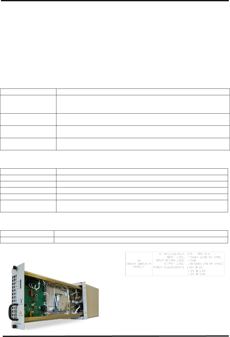
OR A6 Driver Amplifier Module, used
in high power transmitters 1302846
A11 Backplane Board 1301941
A12 Switch Board 1527-1406
A20 LCD Display Board
Exciter Amplifier Chassis Assembly,
110 VAC (1301914) or 220 VAC
(1303228); Appendix B
The chassis assembly is factory set for
operation using 110 VAC or 220 VAC. All
of the modules except the power
amplifier module and the power supply
section of the Control & Monitoring/Power
Supply Module, plug directly into a
backplane board. The backplane board
provides module to module
interconnection as well as interconnection
to remote command and control
connectors.
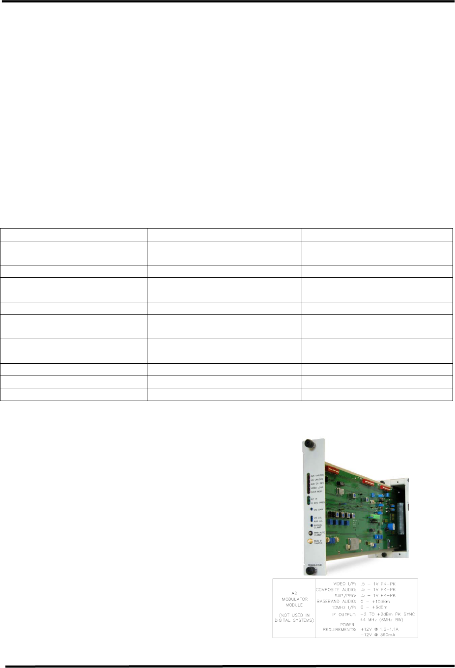
2.1.1 (A2) Modulator Module
Assembly (1301929; Appendix B)
NOTE: The Modulator module is not
present in a translator system
UHF Analog Driver/Transmitter Chapter 2, System Description
& Remote Control Connections
LX Series, Rev. 0 2-2
The (A2) Modulator Assembly contains
the Modulator Board (1301797). The
modulator is broadcast quality and
provides front panel access to control and
monitoring points. The video level is
controlled through a sync tip clamp and
sync and white clipping circuitry. The IF
oscillator is oven controlled and locked to
a 10 MHz reference for stability. The IF
signal is fed through a SAW filter for
precise sideband shaping. The Modulator
operates using either the baseband audio
and video inputs or the 4.5-MHz
composite input to produce a diplexed,
modulated, and on-channel frequency
visual + aural RF output that is cabled to
the IF Processing Module.
Table 2-2. Modulator Front Panel Switch
SWITCH FUNCTION
MAN/AUTO CLAMP
SW1
When Manual Clamp is selected, the video level is set by the
Manual Bias Pot R67 located on the board. (NOTE: The pot is
factory set and needs no adjustment by the customer).
When Auto Clamp is selected, the video level control circuit
will automatically increase or decrease the video to maintain
the desired video level.
Table 2-3. Modulator Front Panel Status Indicators
LED FUNCTION
AUR UNLOCK
DS5 (Red)
When lit it indicates that the 4.5 MHz VCO and the 10 MHz reference
are not PLL locked.
VIS UNLOCK
DS6 (Red)
When lit it indicates that the 45.75 MHz VCXO and the 10 MHz
reference signal are not PLL locked.
AUD OV DEV
DS4 (Red) When lit it indicates the deviation level is more than ±80kHz
VIDEO LOSS
DS1 (Red) When lit it indicates the Video Input to the transmitter is lost.
OVER MOD
DS3 (Red) When lit it indicates the Video input level is too high.
ALT IF
DS7 (Green) When lit it indicates that external or alternate 4.5MHZ is present.
10 MHz PRES
DS2 (Green)
When lit it indicates that a 10MHz reference is present to the
transmitter.
Table 2-4. Modulator Front Panel Control Adjustments
POTENTIOMETERS DESCRIPTION
Video Gain (R42) Adjusts the level of the output video.
Visual Level (R214) Adjusts the Visual IF level that combines with the Aural IF.
Aural Level (R243) Adjusts the Aural IF level that combines with the Visual IF.
MONO (R110) Adjusts the deviation level of the balanced audio input.
STEREO (R132) Adjusts the deviation level of the composite audio input.
SAP/PRO (R150) Adjusts the deviation level of the subcarrier audio input.
Table 2-5. Modulator Front Panel Sample
SMA CONNECTOR DESCRIPTION
MOD IF SAMPLE (J10) Sample of the combined Aural IF and Visual IF signals.
UHF Analog Driver/Transmitter Chapter 2, System Description
& Remote Control Connections
LX Series, Rev. 0 2-3
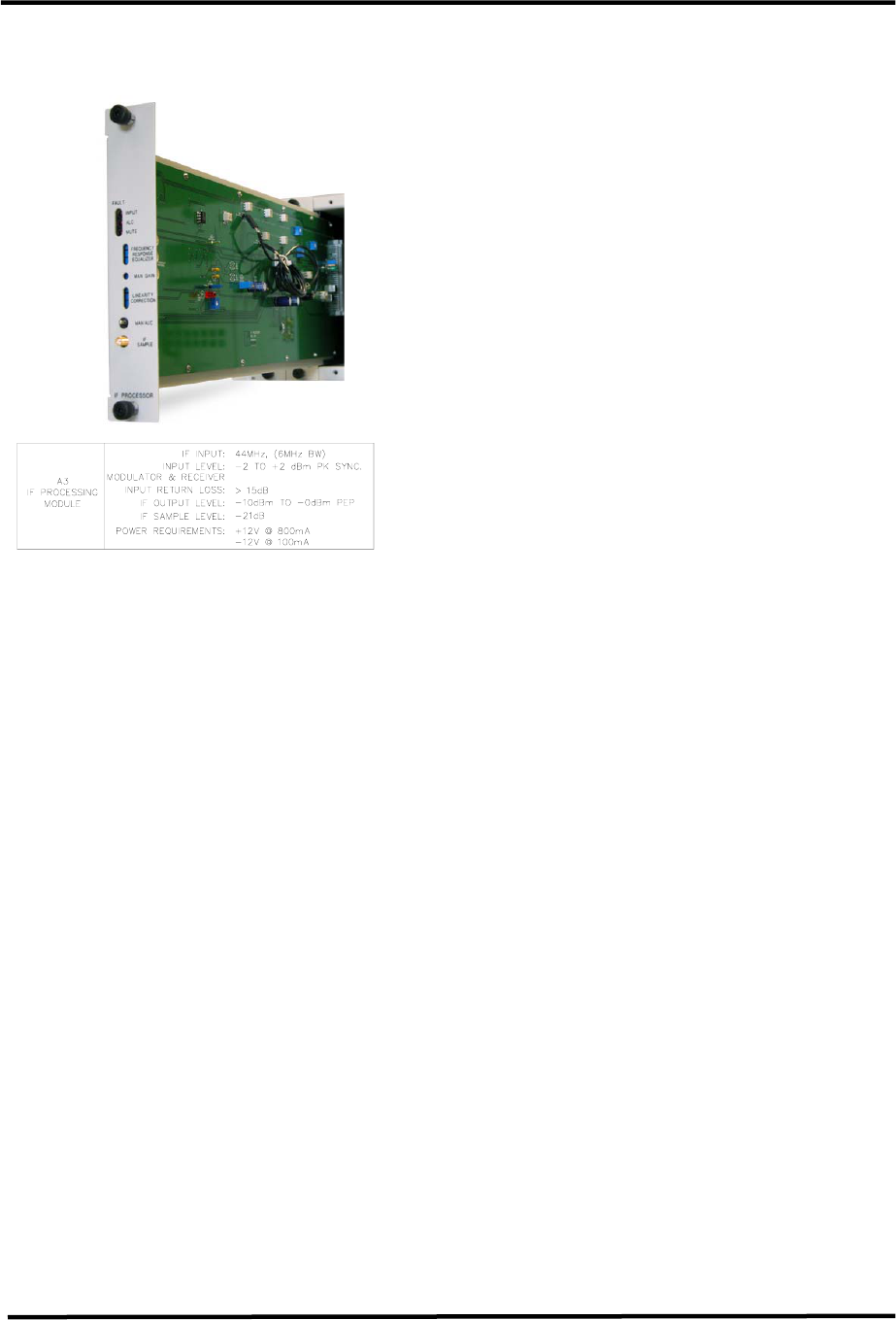
2.1.2 (A3) IF Processor Module
Assembly (1301938; Appendix B)
The (A3) IF Processor Assembly contains
the IF Processor Board (1301977). The IF
Processor provides pre-correction to
ensure broadcast quality output signal.
The pre-correction consists of amplitude
linearity correction, Incidental Carrier
Phase Modulation (ICPM) correction and
frequency response correction.
The IF Processor module is configured
either for an analog or digital system.
Pin 13C of the IF Processor module is
grounded in analog systems and left not
connected in digital systems. An IF
Processor Interlock signal is used to
report the presence of the IF Processor
module to the Control Monitoring board.
If the IF Processor interlock signal is not
present, the LX Series 100 Watt
Transmitter/Exciter Driver RF output is
Muted (turned off). If an analog IF
Processor module is installed and the
Modulation Present signal is not true,
the LX Series 100 Watt Transmitter /
Exciter Driver output is Muted (turned
off).
The Control & Monitoring/Power Supply
module uses the IF Processor module for
System output power control. Through
the front panel display or a remote
interface, an operator can set the
transmitter's RF output power. The
range of RF power adjustment is
between 0% (full off) and 105% (full
power plus). A front panel IF Processor
module potentiometer sets the upper
limit of RF power at 120%. The
system's Control Monitoring board
compares the RF Power Monitoring
module RF power level with the desired
level and uses the IF Power Control PWM
line to correct for errors.
In digital systems, a digital level control
(DLC) voltage is generated on the IF
Processor module and sent to an
external digital modulator (DT1C). RF
power control is implemented by
changing the DLC voltage provided to
the external digital modulator. The 'RF
High' potentiometer sets the upper
adjusted range of RF control circuit
output to 120%.
The IF Processor module provides a
reference ALC voltage to the system's
Upconverter. When the ALC voltage
decreases, the Upconverter
automatically lowers the system output
power through the AGC circuits.
The IF Processor module has a front
panel switch to select Auto or Manual
ALC. When Manual ALC is selected, the
reference ALC voltage is set by a front
panel potentiometer. In this condition,
the RF power level control circuit is
removed from use. When the ALC select
switch is changed to Auto, the RF power
level control circuit will start at low
power and increase the RF output until
the desired output power is attained.
The IF Processor module Modulation
Present signal is monitored. If the
modulation level is too low or non-
existent, a Modulation Present fault is
reported to the Control Monitoring
board. When the controller detects this
fault, it can be set to Automatically Mute
UHF Analog Driver/Transmitter Chapter 2, System Description
& Remote Control Connections
LX Series, Rev. 0 2-4
the transmitter or in Manual mode the
transmitter will continue to operate at
25% output.
The IF Processor module Input Signal
level is monitored. If the signal level is
too low or non-existent, an Input fault is
reported on the Control Monitoring
board. When the IF Processor board
detects an Input Signal fault it
automatically Mutes the transmitter.
The system controller does not Mute on
an IF Processor Input fault.
Table 2-6. IF Processor Front Panel Switch
SWITCH FUNCTION
MAN/AUTO ALC
When Manual ALC is selected, the reference ALC voltage is set
by the ALC Gain front panel potentiometer.
When Auto ALC is selected, the IF level control circuit will
automatically increase the IF output until the desired output
power is attained.
Table 2-7. IF Processor Front Panel Status Indicators
LED FUNCTION
INPUT FAULT (Red) When lit it indicates that there is a loss of the IF Input signal to the
IF Processor. Transmitter can be set to Mute on an IF Input Fault.
ALC Fault (Red)
When lit it indicates that the required gain to produce the desired
output power level has exceeded the operational range of the ALC
circuit. The LED will also be lit when ALC is in Manual.
MUTE (Red) When lit it indicates that the IF input signal is cut back but the
enable to the Power Supply is present and the +32 VDC remains on.
Table 2-8. IF Processor Front Panel Control Adjustments
POTENTIOMETERS DESCRIPTION
FREQUENCY
RESPONSE
EQUALIZER
These three variable resistors, R103, R106 & R274, adjust the
depth of gain for the three stages of frequency response correction.
ALC GAIN Adjusts the gain of the transmitter when the transmitter is in the
Auto ALC position.
MAN GAIN Adjusts the gain of the transmitter when the transmitter is in the
Manual ALC position.
LINEARITY
CORRECTION
These three variable resistors adjust the threshold cut in for the
three stages of linearity pre-correction. R211 and R216, the top
two pots, are adjusted to correct for in phase amplitude distortions.
R 231, the bottom pot, is adjusted to correct for quadrature phase
distortions.
Table 2-9. IF Processor Front Panel Sample
SMA CONNECTOR DESCRIPTION
IF SAMPLE Sample of the pre-corrected IF output of the IF Processor
UHF Analog Driver/Transmitter Chapter 2, System Description
& Remote Control Connections
LX Series, Rev. 0 2-5
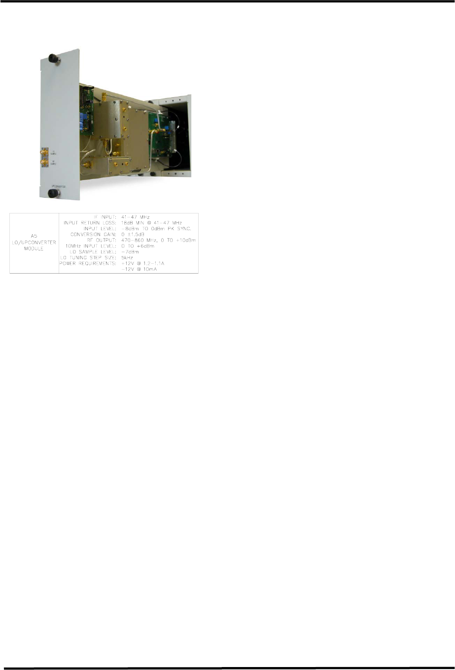
2.1.3 (A5) LO/Upconverter Module
Assembly (1301930; Appendix B)
The (A5) LO/Upconverter Module
Assembly contains a front panel LED
display board (1303033), a UHF Filter
(1007-1101), a UHF Generator Board
(1585-1265) and a LO/Upconverter
Assembly (1303039). The
LO/Upconverter Assembly contains the
LO/Upconverter Board (1302132).
The LX Series Upconverter converts an
IF input signal to a RF output signal on
the desired channel frequency using a
high stability oven controlled oscillator
with very low phase noise and an
Automatic Level Control (ALC) for stable
output signal level.
Several control voltages are used for
transmitter power control. Automatic
gain control (AGC) circuits set the RF
output level of the transmitter system.
AGC #1 is provided by the
Transmitter/Exciter Driver Power
Amplifier module. This voltage is used
by the Upconverter to maintain a
constant RF output level at the Power
Amplifier module output. If this voltage
exceeds 0.9 VDC, the system is in an
over-drive condition. The 0.9 VDC over-
driver threshold is set by a front panel
Upconverter module potentiometer.
When an over-drive condition is
detected, the Upconverter module
reduces its RF output level. For values
less than 0.9 VDC, the Upconverter uses
the AGC #1 voltage for automatic gain
control by setting it's RF output to
maintain AGC #1 equal to the AGC
voltage set by another front panel
potentiometer. When the Upconverter is
set for manual gain, the RF output of the
Upconverter is set by the front panel
AGC potentiometer. In manual gain
operation, the AGC #1 feedback voltage
from the PA is not used to adjust the RF
level unless an over-drive condition is
detected.
AGC #2 is provided by each of the
optional external amplifier modules.
Diodes are used in each of the external
amplifier forward power circuits to
capture the highest detected sample
voltage. This voltage is used by the
Upconverter to maintain a constant RF
output of the system. As with AGC #1,
the Upconverter module reduces its RF
output level if AGC #2 is too high. AGC
#1 and ACG #2 are diode ORed together
in the Upconverter gain circuit. Both
AGC voltages are first reduced by an on-
board potentiometer before being
amplified. If an over-drive condition
does not exist, the higher of the two
AGC voltages is used to control the
Upconverter gain circuit. An AFC Voltage
is generated to control the VCXO of the
UHF Generator portion of the
Upconverter module. The typical AFC
voltage is 0.5 VDC but it can be as high
as +1.5 VDC.
The Upconverter can operate on either
it's internal 10 MHz source or on a 10
MHz external reference signal. When an
external 10 MHz source is present on
J10, it is automatically selected. An
external reference present signal is
provided to the controller for display
purposes. The selected 10 MHz signal
from the Upconverter is buffered then
UHF Analog Driver/Transmitter Chapter 2, System Description
& Remote Control Connections
LX Series, Rev. 0 2-6
sent to the backplane on two ports. One
port is sent to the Modulator module, if
present, and the other is routed to a
BNC connector (J11) on the backplane
for a system 10 MHz output signal.
A National Semiconductor frequency
synthesizer IC is used in the frequency
conversion of the IF signal to a RF
signal. The frequency synthesizer IC
uses a 10MHz reference frequency for
signal conversion. Typically the IF input
frequency is 45.75 MHz for analog
system and 44 MHz for DTV. To obtain
different output RF frequencies, the
synthesizer IC is serial programmed by
the Control Monitoring board. The part
is programmed to use a 5 kHz phase
detection frequency. With a 10 MHz
input signal, the R counter is set to
2000. With these settings the N counter
is set to the desired LO frequency in kHz
/ 5 kHz. The maximum LO frequency
setting with these parameters is
1310.715 MHz.
Example:
For a Frequency RF Out = 517.125 MHz,
N = 517125 kHz / 5 kHz = 103425
An Upconverter PLL Lock indicator is
used to insure that the frequency control
circuits are operating properly. When
the Upconverter PLL is locked, the
frequency synthesizer IC is programmed
and the Power Amplifier module(s) can
be enabled.
The RF output of the LO/Upconverter
Module is at J23 on the rear chassis.
Table 2-10. LO/Upconverter Front Panel Switch
SWITCH FUNCTION
MAN/AUTO AGC
When Manual AGC is selected, the reference AGC voltage is
set by the AGC Manual Gain front panel potentiometer.
When Auto AGC is selected, the RF power level control circuit
will automatically increase the RF output until the desired
output power is attained.
Table 2-11. LO/Upconverter Front Panel Status Indicator
LED FUNCTION
AGC CUTBACK
(Red)
When lit it indicates that the required gain to produce the desired
output power level has exceeded the level set by the AGC Cutback
(Override) adjust. Transmitter will cut back power to 25%
Table 2-12. LO/Upconverter Front Panel Control Adjustments
POTENTIOMETERS DESCRIPTION
MAN GAIN ADJ Adjusts the gain of the transmitter when the transmitter is in the
Manual AGC position.
AGC CUTBACK ADJ
(AGC OVERRIDE)
Adjusts the point at which the transmitter will cut back in power
when the Transmitter is in the Auto AGC position.
Table 2-13. LO/Upconverter Front Panel Samples
SMA CONNECTOR DESCRIPTION
LO SAMPLE Sample of the LO signal to the Upconverter as generated by the
UHF Generator Board.
RF SAMPLE Sample of the On Channel RF Output of the Upconverter
UHF Analog Driver/Transmitter Chapter 2, System Description
& Remote Control Connections
LX Series, Rev. 0 2-7
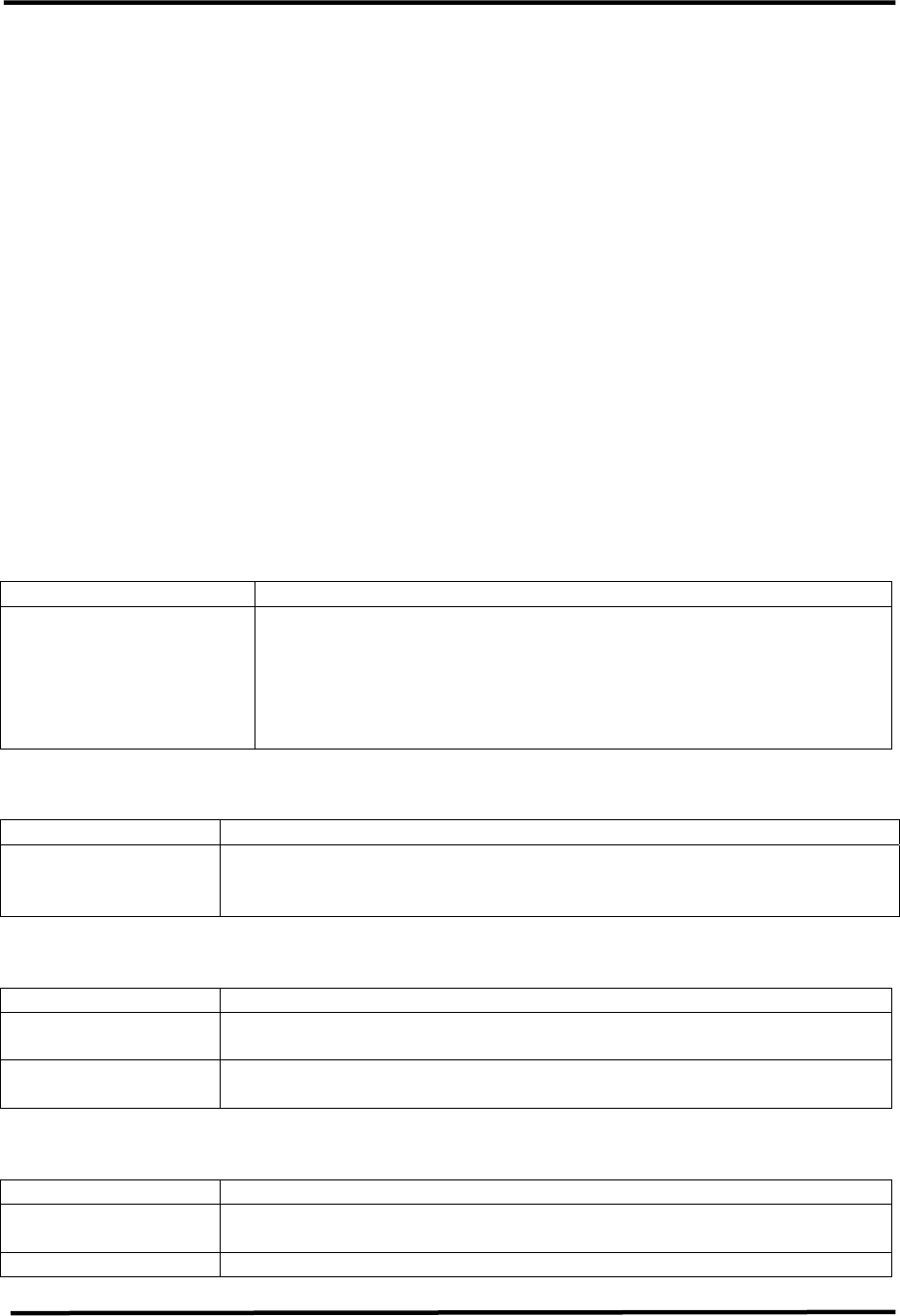
2.1.4 (A4) Control/Power Supply
Module Assembly (110 VAC,
1301936 or 220 VAC, 1303229;
Appendix B)
8
A
4 A
The (A4) Control & Monitoring/Power
Supply Assembly is configured at the
factory for operation at 110 VAC or 220
VAC. The assembly made up of a Control
Board (1302021), a Power Protection
Board (1302837) and a Switch Board
(1527-1406). The Assembly also
contains a switching power supply that
provides ±12 VDC to the rest of the
modules in the chassis and +32 VDC to
the Power Amplifier module.
The Assembly provides all transmitter
control and monitoring functions. The
Front panel LCD allows monitoring of
system parameters, including forward
and reflected power, transistor currents,
module temperatures and power supply
voltages.
Table 2-14. Controller/Power Supply Display
DISPLAY FUNCTION
LCD
A 4 x 20 display providing a four-line readout of the internal
functions, external inputs, and status. See Chapter 3,
Controller/Power Supply Display Screens, for a listing of displays.
Table 2-15. Controller/Power Supply Status Indicator
LED FUNCTION
OPERATE
(green)
When lit it indicates that the transmitter is in the Operate Mode. If
transmitter is Muted the Operate LED will stay lit, the transmitter
will remain in Operate, until the input signal is returned.
FAULT
(red or green)
Red indicates that a problem has occurred in the transmitter. The
transmitter will be Muted or placed in Standby until the problem is
corrected.
DC OK
( red or green )
Green indicates that the switchable fuse protected DC outputs that
connect to the modules in the transmitter are OK.
Table 2-16. Controller/Power Supply Control Adjustments
POTENTIOMETERS DESCRIPTION
DISPLAY CONTRAST Adjusts the contrast of the display for desired viewing of screen.
UHF Analog Driver/Transmitter Chapter 2, System Description
& Remote Control Connections
LX Series, Rev. 0 2-8
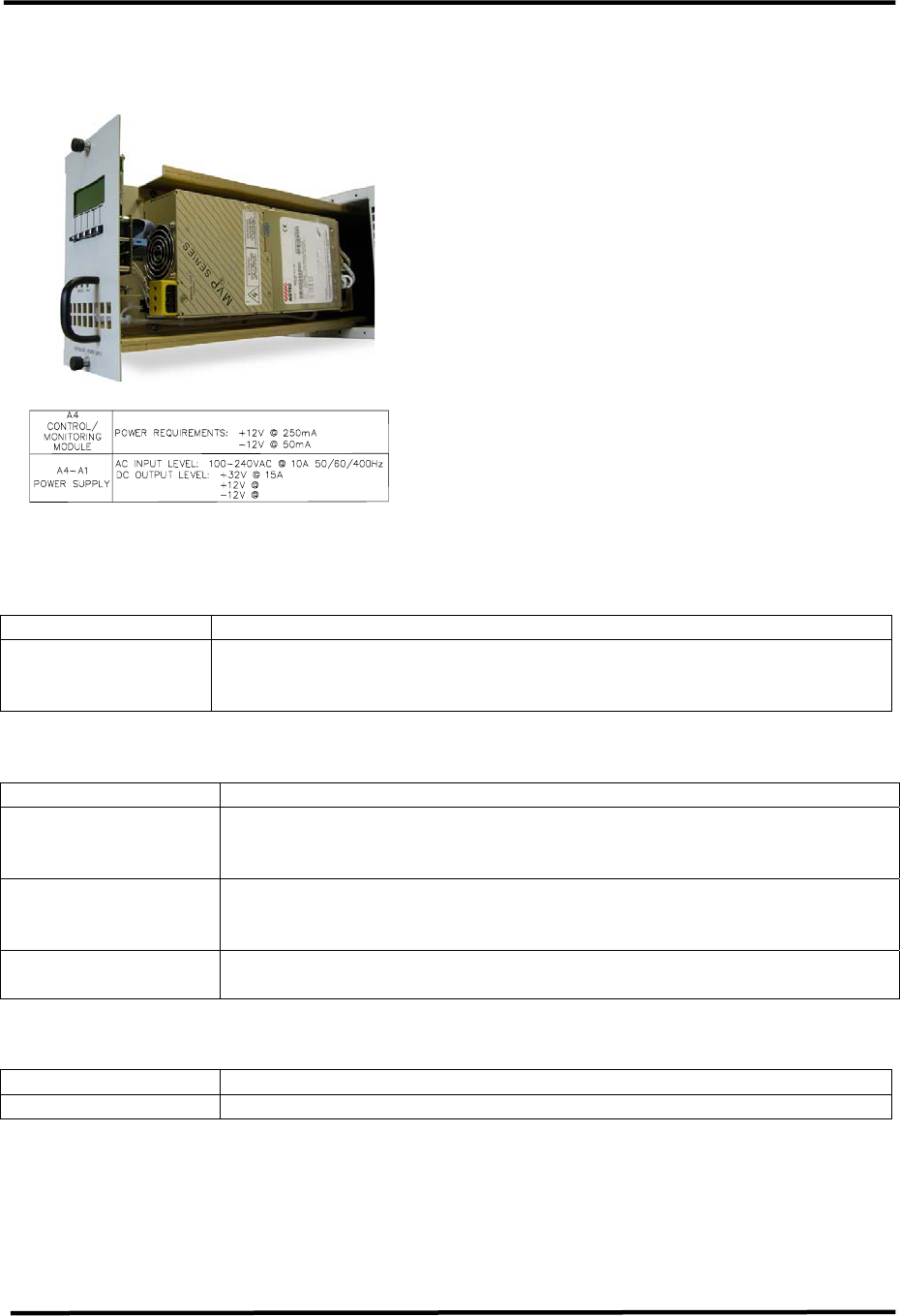
2.1.5 (A6) Power Amplifier Module
Assembly, Exciter, 100W Transmitter
(1301923; Appendix B)
NOTE: The (A6) Power Amplifier Module
Assembly (1301923) is used in the 10-
100 Watt Transmitter.
The (A6) Power Amplifier Module
Assembly is made up of a Coupler Board
Assembly (1301949), an Amplifier
Control Board (1301962), a 1 Watt
Module Assembly (1302891), a TFS 40W
UHF Module (1206693) and a RF Module
Pallet, Philips (1300116).
The Power Amplifier Module contains
Broadband LDMOS amplifiers that cover
the entire UHF band with no tuning
required. They amplify the RF to the
10W to 100W output power level of the
transmitter.
The Power Amplifier of the
Transmitter/Exciter Driver is used to
amplify the RF output of the
Upconverter module. A cable, located on
the rear chassis, connects the RF output
from the LO/Upconverter at J23 to J24
the RF input to the PA Assembly. This
module contains RF monitoring circuitry
for both an analog and a digital system.
Control and monitoring lines to the
Power Amplifier module are routed
through the floating blind-mate
connector of the Control &
Monitoring/Power Supply module.
The 100 Watt Transmitter/Exciter Driver
Power Amplifier module and any
External Amplifier modules contain the
same control and monitoring board.
This board monitors RF output power,
RF reflected power, the current draw of
amplifier sections, the supply voltage,
and the temperature of the PA heat sink.
The RF power detector circuit outputs
vary with operating frequency. These
circuits must be calibrated at their
intended operating frequency. Front
panel adjustment potentiometers are
used to calibrate the following:
Table 1: Power Amplifier Calibration
Adjustments in Analog Systems
R201 Reflected Power Cal
R202 Visual / Forward Power Cal
R203 Aural Power Cal
R204 Visual Offset Zero
R205 Aural Null
In analog systems, the Aural power of
an Exciter Driver Power Amplifier and
the Aural power of any external
amplifier will not be reported by the
system Control Monitoring module.
Additionally the Visual power of these
amplifiers, is reported as Forward Power
just like in digital systems. In analog
systems, aural and visual power will only
be reported for the final system RF
output.
In digital systems, the Forward power of
an Exciter Driver Power Amplifier and
the Forward power of any external
amplifier, is reported by the system
Control Monitoring module.
If the Control Monitoring module is
monitoring a 5-50 Watt digital or 10-100
Watt analog Transmitter, system power
is measured in the Power Amplifier
module. The wired connections are
transferred through the power supply
connector to the backplane board on a
five position header. All four positions
UHF Analog Driver/Transmitter Chapter 2, System Description
& Remote Control Connections
LX Series, Rev. 0 2-9
of control board switch SW1 must be set
on to route these lines as the system's
RF power signals. In systems of output
power greater than 50 Watts digital or
100 Watts analog, system power is
monitored by an external module that is
connected to TB31 and control board
SW1 switches must be set off.
The Forward Power of the
Transmitter/Exciter Driver Power
Amplifier module is routed to the
Upconverter module as AGC #1. A
system over-drive condition is detected
when this value rises above 0.9 VDC.
When an over-drive condition is
detected, the Upconverter module
reduces its RF output level. For values
less than 0.9 VDC, the Upconverter uses
this voltage for automatic gain.
Table 2-17. Power Amplifier Status Indicator
LED FUNCTION
ENABLED
(Green)
When lit Green, it indicates that the PA is in the Operate Mode. If a
Mute occurs, the PA will remain Enabled, until the input signal is
returned.
DC OK
(Green)
When lit Green, it indicates that the fuse protected DC inputs to the
PA module are OK.
TEMP
(Green)
When lit Green, it indicates that the temperature of the heatsink
assembly in the module is below 78˚C.
MOD OK
(Green)
When lit Green, it indicates that the PA Module is operating and has
no faults.
Table 2-18. Power Amplifier Control Adjustments
POTENTIOMETERS DESCRIPTION
RFL CAL Adjusts the gain of the Reflected Power monitoring circuit
VISUAL CAL Adjusts the gain of the Visual / Forward Power monitoring circuit
AURAL CAL Adjusts the gain of the Aural Power monitoring circuit
VISUAL ZERO Adjusts the offset of the Forward Power monitoring circuit
AURAL NULL Adjusts the offset of the Forward Power monitoring circuit based on
the Aural signal level.
Table 2-19. Power Amplifier Sample
DISPLAY FUNCTION
FWD SAMPLE RF sample of the amplified signal being sent out the module on J25.
2.1.5.1 (A6) Driver Amplifier Module
Assembly (1302846; Appendix B)
NOTE: The (A6) Driver Amplifier Module
Assembly (1302846) replaces the Power
Amplifier Module Assembly (1301923)
when the amplifier module is used as a
driver for any external PA assemblies.
The (A6) Power Amplifier Module
Assembly is made up of a Coupler Board

UHF Analog Driver/Transmitter Chapter 2, System Description
& Remote Control Connections
LX Series, Rev. 0 2-10
Assembly (1301949), an Amplifier
Control Board (1301962), a 1 Watt
Module Assembly (1302891) and a TFS
40W UHF Module (1206693).
The Driver Power Amplifier Module
contains Broadband LDMOS amplifiers
that cover the entire UHF band with no
tuning required. They amplify the RF to
the power level, 7 Watts Peak of Sync is
maximum, that is needed to drive the
external amplifiers to the output power
level of the transmitter.
The Driver Power Amplifier is used to
amplify the RF output of the
Upconverter module. A cable, located on
the rear chassis, connects the RF output
from the LO/Upconverter at J23 to J24
the RF input to the driver PA Assembly.
This module contains RF monitoring
circuitry for both an analog and a digital
system. Control and monitoring lines to
the Driver Power Amplifier module are
routed through the floating blind-mate
connector of the Control &
Monitoring/Power Supply module.
The Driver Power Amplifier module and
any External Amplifier modules contain
the same control and monitoring board.
This board monitors RF output power,
RF reflected power, the current draw of
amplifier sections, the supply voltage,
and the temperature of the PA heat sink.
The RF power detector circuit outputs
vary with operating frequency. These
circuits must be calibrated at their
intended operating frequency. Front
panel adjustment potentiometers are
used to calibrate the following:
Table 2: Power Amplifier Calibration
Adjustments in Analog Systems
R201 Reflected Power Cal
R202 Visual / Forward Power Cal
R203 Aural Power Cal
R204 Visual Offset Zero
R205 Aural Null
In analog systems, the Aural power of
an Exciter Driver Power Amplifier and
the Aural power of any external PA
amplifiers will not be reported by the
system Control Monitoring module.
Additionally the Visual power of these
amplifiers, is reported as Forward Power
just like in digital systems. In analog
systems, aural and visual power will only
be reported for the final system RF
output.
In digital systems, the Forward power of
an Exciter Driver Power Amplifier and
the Forward power of any external
amplifiers, are reported by the system
Control Monitoring module.
If the Control Monitoring module is
monitoring a 10-100 Watt Transmitter,
system power is measured in the Power
Amplifier module. The wired
connections are transferred through the
power supply connector to the
backplane board on a five position
header. All four positions of control
board switch SW1 must be set on to
route these lines as the system's RF
power signals. In systems of output
power greater than 100 Watts, system
power is monitored by an external
module that is connected to TB31. In
this configuration switches SW1 on the
control board must be set off.
The Forward Power of the Exciter Driver
Power Amplifier module is routed to the
Upconverter module as AGC #1. A
system over-drive condition is detected
when this value rises above 0.9 VDC.
When an over-drive condition is
detected, the Upconverter module
reduces its RF output level.
For values less than 0.9 VDC, the
Upconverter uses this voltage for
automatic gain.
UHF Analog Driver/Transmitter Chapter 2, System Description
& Remote Control Connections
LX Series, Rev. 0 2-11
Table 2-20. Driver Amplifier Status Indicator
LED FUNCTION
ENABLED
(Green)
When lit Green, it indicates that the PA is in the Operate Mode. If a
Mute occurs, the PA will remain Enabled, until the input signal is
returned.
DC OK
(Green)
When lit Green, it indicates that the fuse protected DC inputs to the
PA module are OK.
TEMP
(Green)
When lit Green, it indicates that the temperature of the heatsink
assembly in the module is below 78˚C.
MOD OK
(Green)
When lit Green, it indicates that the PA Module is operating and has
no faults.
Table 2-21. Driver Amplifier Control Adjustments
POTENTIOMETERS DESCRIPTION
RFL CAL Adjusts the gain of the Reflected Power monitoring circuit
VISUAL CAL Adjusts the gain of the Visual / Forward Power monitoring circuit
AURAL CAL Adjusts the gain of the Aural Power monitoring circuit
VISUAL ZERO Adjusts the offset of the Forward Power monitoring circuit
AURAL NULL Adjusts the offset of the Forward Power monitoring circuit based on
the Aural signal level..
Table 2-22. Driver Amplifier Sample
DISPLAY FUNCTION
FWD SAMPLE RF sample of the amplified signal being sent out the module on J25.
2.1.6 RF Output Assemblies
The RF output from the driver power
amplifier is at the RF output jack, an “N”
connector J25, PA RF Output, of the
chassis assembly. If this assembly is
used as a driver the output connects to
the input of the PA Assembly mounted
beneath the Exciter Assembly. If this
assembly is used as a 10W to 100W
transmitter, then the output connects
directly to the bandpass filter for the
system.
The RF output of the transmitter is
typically connected to a bandpass filter
and then to a trap filter mounted on the
rear of the assembly. The bandpass and
trap filters are tuned to eliminate
unwanted sideband and harmonic
frequencies. Located on the output of
the trap filter is a BNC output sample
jack that can be used for test purposes.
2.2 Control and Status
The control and status of the
exciter/amplifier Chassis assembly are
found by operating the front panel
display screen on the front of the
assembly. Detailed information on the
use of the screens is found in chapter 3.
2.2.1 Front Panel Display Screens
A 4 x 20 display located on the front of
the Control & Monitoring/Power Supply
Module is used in the LX Series
transmitter for control of the operation
and display of the operating parameters
of the transmitter.
2.3 System Operation
When the transmitter is in operate, as set
by the menu screen located on the
Control & Monitoring Module. The IF

UHF Analog Driver/Transmitter Chapter 2, System Description
& Remote Control Connections
LX Series, Rev. 0 2-12
Processor will be enabled, the mute
indicator on the front panel will be
extinguished. The +32 VDC stage of the
Power Supply in the Control & Monitoring
Module is enabled, the operate indicator
on the front panel is lit and the DC OK on
the front panel should also be green.
The enable and DC OK indicators on the
PA Module will also be green.
When the transmitter is in standby. The
IF Processor will be disabled, the mute
indicator on the front panel will be red.
The +32 VDC stage of the Power Supply
in the Control & Monitoring Module is
disabled, the operate indicator on the
front panel will be extinguished and the
DC OK on the front panel should remain
green. The enable indicator on the PA
Module is also extinguished.
If the transmitter does not switch to
Operate when the operate menu is
switched to Operate, check that all faults
are cleared and that the remote control
terminal block stand-by signal is not
active.
The transmitter can be controlled by the
presence of a modulated input signal. If
the input signal to the transmitter is lost,
the transmitter will automatically cutback
and the input fault indicator on the IF
Processor module will light. When the
video input signal returns, the
transmitter will automatically return to
full power and the input fault indicator
will be extinguished.
2.3.1 Principles of Operation
Operating Modes
This transmitter is either operating or in
standby mode. The sections below
discuss the characteristics of each of
these modes.
Operate Mode
Operate mode is the normal mode for
the transmitter when it is providing RF
power output. To provide RF power to
the output, the transmitter will not be in
mute. Mute is a special case of the
operate mode where the +32 VDC
section of the power supply is enabled
but there is no RF output power from
the transmitter. This condition is the
result of a fault condition that causes
the firmware to hold the IF Processor
module in a mute state.
Operate Mode with Mute Condition
The transmitter will remain in the
operate mode but will be placed in mute
when the following fault conditions
exists in the transmitter.
• Upconverter is unlocked
• Upconverter module is not present
• IF Processor module is not present
• Modulator (if present) is in
Aural/Visual Mute
Entering Operate Mode
Entering the operate mode can be
initiated a few different ways by the
transmitter control board. A list of the
actions that cause the operate mode to
be entered is given below:
• A low on the Remote Transmitter
Operate line.
• User selects "OPR" using switches
and menus of the front panel.
• Receipt of an “Operate CMD” over
the serial interface.
There are several fault or interlock
conditions that may exist in the
transmitter that will prevent the
transmitter from entering the operate
mode. These conditions are:
• Power Amplifier heat sink
temperature greater than 78˚C.
• Transmitter is Muted due to
conditions listed above.
UHF Analog Driver/Transmitter Chapter 2, System Description
& Remote Control Connections
LX Series, Rev. 0 2-13
• Power Amplifier Interlock is high
indicating that the amplifier is not
installed.
Standby Mode
The standby mode in the transmitter
indicates that the output amplifier of the
transmitter is disabled.
Entering Standby Mode
Similar to the operate mode, the
standby mode is entered using various
means. These are:
• A low on the Remote Transmitter
Stand-By line.
• Depressing the “STB” key on
selected front panel menus.
• Receipt of a “Standby CMD” over the
serial interface.
Operating Frequency
The LX Series transmitter controller is
designed to operate on UHF frequencies.
The exact output frequency of the
transmitter can be set to one of the
standard UHF frequencies, or it can be
set to a custom frequency using
software set-up menus. Since RF
performance of the transmitter requires
different hardware for different
frequency bands, not all frequency
configurations are valid for a specific
transmitter. The Power detectors in the
transmitter have frequency dependency,
therefore detectors of power amplifiers
are calibrated at their frequency of use.
The detectors for System RF monitoring
are also calibrated at the desired
frequency of use.
Table 2-23: UHF Television Frequencies
CH
# FREQUENCY CH
# FREQUENCY CH
# FREQUENCY
14 470-476 MHz 38 614-620 MHz 61 752-758 MHz
15 476-482 MHz 39 620-626 MHz 62 758-764 MHz
16 482-488 MHz 40 626-632 MHz 63 764-770 MHz
17 488-494 MHz 41 632-638 MHz 64 770-776 MHz
18 494-500 MHz 42 638-644 MHz 65 776-782 MHz
19 500-506 MHz 43 644-650 MHz 66 782-788 MHz
20 506-512 MHz 44 650-656 MHz 67 788-794 MHz
21 512-518 MHz 45 656-662 MHz 68 794-800 MHz
22 518-524 MHz 46 662-668 MHz 69 800-806 MHz
23 524-530 MHz 47 668-674 MHz 70 806-812 MHz
24 530-536 MHz 48 674-680 MHz 71 812-818 MHz
25 536-542 MHz 49 680-686 MHz 72 818-824 MHz
26 542-548 MHz 50 686-692 MHz 73 824-830 MHz
27 548-554 MHz 51 692-698 MHz 74 830-836 MHz
28 554-560 MHz 52 698-704 MHz 75 836-842 MHz
29 560-566 MHz 53 704-710 MHz 76 842-848 MHz
30 566-572 MHz 54 710-716 MHz 77 848-854 MHz
31 572-578 MHz 55 716-722 MHz 78 854-860 MHz
32 578-584 MHz 56 722-728 MHz 79 860-866 MHz
33 584-590 MHz 57 728-734 MHz 80 866-872 MHz
34 590-596 MHz 58 734-740 MHz 81 872-878 MHz
35 596-602 MHz 59 740-746 MHz 82 878-884 MHz
36 602-608 MHz 60 746-752 MHz 83 884-890 MHz
37 608-614 MHz
UHF Analog Driver/Transmitter Chapter 2, System Description
& Remote Control Connections
LX Series, Rev. 0 2-14
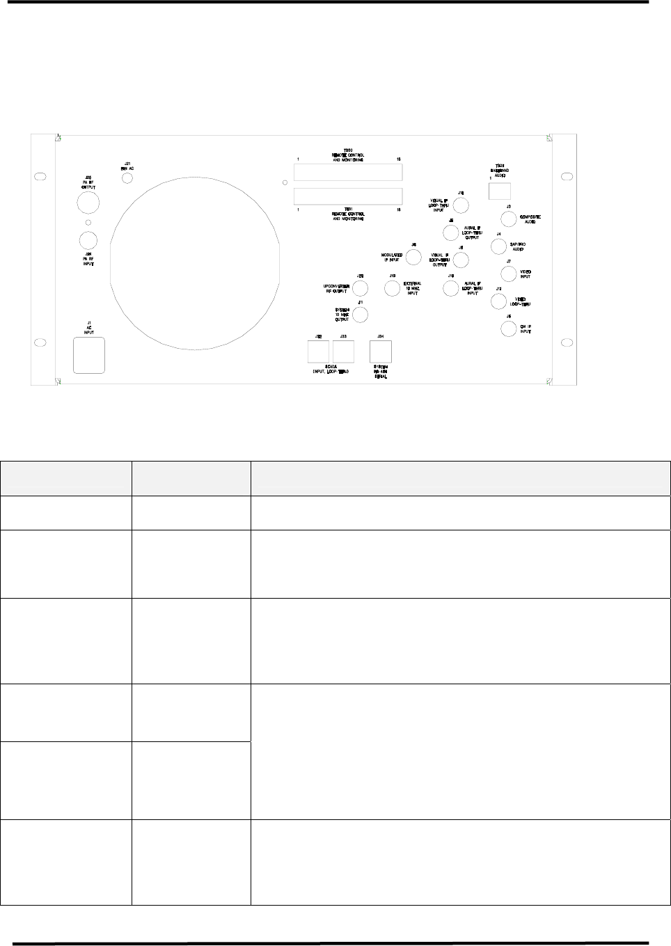
2.4 Customer Remote Connections
The remote monitoring and operation of
the transmitter is provided through jacks
TB30 and TB31 located on the rear of the
chassis assembly. If remote connections
are made to the transmitter, they must
be made through plugs TB30 and TB31
at positions noted on the transmitter
interconnect drawing and Table 2-20.
Table 2-24: LX Series Chassis Assembly Hard Wired Remote Interface Connections to
TB30 or TB31, 18 pos. Terminal Blocks Located on the Rear of the Assembly
Signal Name Pin
Designations Signal Type/Description
RMT Transmitter
State TB30-1 Discrete Open Collector Output - A low indicates that the
transmitter is in the operate mode.
RMT Transmitter
Interlock TB30-2
Discrete Open Collector Output - A low indicated the
transmitter is OK or completes a interlock daisy chain.
When the transmitter is not faulted, the interlock circuit
is completed.
RMT Transmitter
Interlock
Isolated Return
TB30-3
Ground - Configurable ground return which can be either
jumpered directly to ground or it can be the “source” pin
of an FET so that the transmitter interlock can be daisy
chained with other transmitters. This signal does not
directly interface to the microcontroller.
RMT AUX IO 1 TB30-4
RMT AUX IO 2 TB30-5
Discrete Open Collector Inputs, Discrete Open Drain
Outputs, or 0 - 5 VDC Analog Input - When used as an
output, this line is pulled to +5 VDC with a 1.0 kΩ
resistor for logic high and pulled to ground for a low. A
diode allows this line to be pulled up to 12 VDC. When
used as a digital input, this line considers all values over
2 Volts as high and those under 1 volt as low. As an
analog input, this line is protected by a 5.1 zener diode.
RMT
Transmitter
Operate
TB30-6
Discrete Open Collector Input - A pull down to ground on
this line indicates that the transmitter is to be placed into
the operate mode.

UHF Analog Driver/Transmitter Chapter 2, System Description
& Remote Control Connections
LX Series, Rev. 0 2-15
Signal Name Pin
Designations Signal Type/Description
RMT
Transmitter
Stand-By
TB30-7
Discrete Open Collector Input - A pull down to ground on
this line indicates that the transmitter is to be placed into
the standby mode.
RMT Power
Raise TB30-8
Discrete Open Collector Input - A pull down to ground on
this line indicates that the transmitter power is to be
raised.
RMT Power
Lower TB30-9
Discrete Open Collector Input - A pull down to ground on
this line indicates that the transmitter power is to be
lowered.
RMT
System Reflect
Power
TB30-10
Analog Output - 0 to 4.0 V- This is a buffered loop
through of the calibrated “System Reflected Power ” and
indicates the transmitter's reflected output power. The
scale factor is 25%/3.2V.
RMT System
Visual/Forward
Power
TB30-11
Analog Output - 0 to 4.0 V- This is a buffered loop
through of the calibrated “System Visual/Avg. Power ”.
Indicates the transmitter's Visual / Average power. Scale
factor is 100%/3.2V.
RMT
System Aural
Power
TB30-12
Analog Output - 0 to 4.0 V- This is a buffered loop
through of the calibrated “System Aural Power ”.
Indicates the transmitter's forward Aural output power.
The scale factor is 100%/3.2V.
RMT Spare 1 TB30-13 Remote connection to spare module - Use is TBD.
RMT Spare 2 TB30-14 Remote connection to spare module - Use is TBD.
System Reflect
Power TB31-13
Analog Input - 0 to 1.00 V- This is the input of the
“System Reflected Power ” indicating the transmitter's
reflected output power. The scale factor is 25%/0.80V.
System Visual /
Forward Power TB31-14
Analog Input - 0 to 1.00 V- This is the input of the
“System Visual / Forward Power ” indicating the
transmitter's forward Visual / Forward output power. The
scale factor is 100%/0.80V.
System Aural
Power TB31-15
Analog Input - 0 to 1.00 V- This is the input of the
“System Aural Power ” indicating the transmitter's
forward Aural output power. The scale factor is
100%/0.80V.
IF Processor
IF Signal Select TB31-3
Discrete Open Collector Input - A low indicates that the
modulator IF source is to be used by the IF Processor
module. When floating an analog IP Processor module
may use the Modulated IF Input if the IF Processor sled
is so configured.
IF Processor
DLC Voltage TB31-4
Analog Output - 0 to 5.00 V- This is the input of IF
Processor module for digital system RF output power
control.
UC AGC #2
Voltage TB31-5
Auxiliary Analog Input - 0 to 1V- This voltage is used by
the Upconverter for gain control. Linear signal with
display resolution of 0.01 %. Primary signal source is
J34-1.
RMT Ground TB30-15, and
17 Ground pins available through Remote
RMT Ground TB31-1, 2, 6
to 12, and 17 Ground pins available through Remote

UHF Analog Driver/Transmitter Chapter 2, System Description
& Remote Control Connections
LX Series, Rev. 0 2-16
Signal Name Pin
Designations Signal Type/Description
RMT +12 VDC TB30-16
TB31-16
+12 VDC available through Remote w/ 2 Amp re-settable
fuse
RMT -12 VDC TB30-18
TB31-18
-12 VDC available through Remote w/ 2 Amp re-settable
fuse