UTC Fire and Security Americas 612-H20PANIC 60-578 User Manual
UTC Fire & Security Americas Corporation, Inc. 60-578
User Manual
P/N 46-667 • REV J •23APR14 1
Learn Mode Water Resistant Pendant Panic
Button Installation Instructions
Introduction
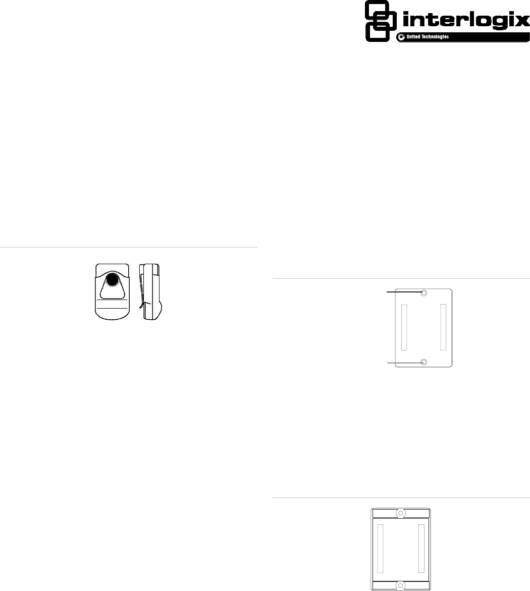
This panic button can be used throughout the premises for
police, medical, or auxiliary alarm activation. When the sensor
button is pressed, the built-in transmitter sends a signal to the
panel (Figure 1 below).
Figure 1: 60-578 Pendant Panic Button
The water-resistant design helps prevent damage in case the
sensor accidently gets wet.
The sensor can be worn using the built-in belt clip or it can be
mounted on a wall in a location convenient for the customer,
using the optional wall-mount holder (kit number 80-116). Each
kit includes the following:
• 5 wall-mount holders;
• 5 pieces of double-sided tape;
• 10 plastic anchors; and
• 10 Phillips-head screws.
You will also need a small Phillips screwdriver (if installing the
optional wall-mount holder).
Installation guidelines
Use the following guidelines when installing this button:
• The transmitter in the button has an open-air range of up
to 1,000 ft. (305 m), but the installation environment may
influence this range.
• When mounting on a wall, determine the best location for
each panic button so it is easily accessible.
• The 3.5 VDC lithium battery will last at least 12 months.
Installation
You can mount the optional wall-mount holder, using anchors
and screws or double-sided tape.
To mount the holder with anchors and screws:
1. Place the holder on the wall at the desired location and
mark the mounting holes with a pencil (Figure 2 below).
Figure 2: Mounting with screws
Mounting hole
Mounting hole
2. Secure the holder to the wall with the screws supplied.
Use the anchors supplied where studs are not present.
To mount the holder with double-sided tape:
1. Peel off the colored backing from the double-sided tape
and place it on back of the holder (Figure 3 below).
Figure 3: Mounting with double-sided tape
Affix
tape
here
2. Peel off the other backing and firmly press the holder
against the mounting surface.

2 Learn Mode Water Resistant Pendant Panic Button Installation Instructions
Programming
This section describes the basic steps for adding the sensor to
panel memory. For complete instructions, refer to the specific
panel’s documentation.
To program the sensor:
1. Set the panel in program mode.
2. When prompted by the panel, enter the appropriate group
number (groups 00 through 07).
Note: For UL installations where the holder is used, the
sensor must be added as a fixed type (sensor groups 00,
02, 04, or 05).
3. When prompted by the panel, select the desired sensor
number.
4. When prompted by the panel, trip the sensor by pressing
the sensor button.
5. Exit from program mode.
Sensor test
To test the sensor:
1. Set the system to the Dealer Sensor Test mode.
2. Press the button on the sensor.
3. Count the number of signals received by the panel,
indicated by interior siren beeps. Seven to eight beeps are
considered acceptable.
4. Test the sensor from several locations within the premises
to check for consistent response.
Battery replacement
To replace the sensor battery:
1. To disassemble the sensor, remove the two screws on the
back of the sensor and separate the front and back plastic.
Caution: You must be free of static electricity before handling
the transmitter circuit board. Touch a grounded, bare metal
surface before touching the circuit board, or wear a grounding
strap.
2. Remove the old battery from its holder and install the new
battery, observing polarity
Caution: Install only the same size and type of battery. Do not
substitute another size or type of battery.
3. Reassemble the sensor.
Note: Be sure to assemble the sensor correctly to ensure
water resistance. Be especially careful not to nick or
damage the rubber gasket lining.
4. Test the sensor as described in “Sensor test” above.
Lithium battery disposal
Lithium batteries that are no longer usable are considered
hazardous waste. Be sure to properly dispose of the old
battery. Contact your local city government for hazardous
waste disposal laws.
Specifications
Compatibility All Interlogix Security Learn Mode panels
Power source 3.6 VDC Saft or Tekcell lithium battery
Enclosure Water-resistant and shock-resistant
Dimensions (LxWxD) 2.25 x 1.75 x 0.75 in. (5.71 x 4.44 x 1.90 cm)
Regulatory information
Manufacturer UTC Fire & Security Americas Corporation, Inc.
1275 Red Fox Rd., Arden Hills, MN 55112-6943,
USA
FCC compliance This device complies with part 15 of the FCC
Rules. Operation is subject to the following two
conditions: (1) This device may not cause harmful
interference, and (2) this device must accept any
interference received, including interference that
may cause undesired operation.
Changes or modifications not expressly approved
by Interlogix can void the user’s authority to
operate the equipment.
FCC ID: B4Z-612-H2OPANIC
IC compliance IC: 1175C-612PANIC
This Class B digital apparatus complies with
Canadian ICES-003.
Cet appareil numérique de la classe B est
conforme à la norme NMB-003 du Canada.
Le fonctionnement est soumis aux deux
conditions suivantes : (1) cet appareil peut ne pas
provoquer d’interférences et (2) cet appareil doit
accepter toutes interférences, y compris les
interférences pouvant provoquer un
fonctionnement non désiré de l’appareil.
U.S. patents 4,855,713, 4,864,636, and others pending.
Contact information
For contact information, see www.utcfireandsecurity.com or
www.interlogix.com.
For technical support, toll-free: 888.437.3287 in the US
including Alaska, Hawaii, Puerto Rico, and Canada. Outside
the toll-free area, contact your dealer.
Copyright © 2014 Interlogix, a UTC Fire & Security Company.
All rights reserved.