UTC Fire and Security Americas 764A-SMOKE User Manual newsmoke
UTC Fire & Security Americas Corporation, Inc. newsmoke
Exhibit G

Page 1
System Sensor Smoke Sensor
System Sensor Smoke
Sensor Model 2100ARFT
Document Number: 466-xxxx Rev. A PRELIMINARY
August 1998
INSTALLATION
INSTRUCTIONS
Product Summary
The System Sensor™ Smoke Sensor Model 2100ARFT
(smoke alarm) is a Learn Mode, wireless, photoelectric
smoke sensor with a self-contained alarm siren, a low-
battery annunciator, and a status light. The smoke
alarm is part of a security/fire alarm system and com-
municates with the system’s control panel.
Figure 1 illustrates the smoke sensor’s parts.
Installation Guidelines
νAvoid installing the unit until all contsruction is
completed. The mounting ring may be pre-
installed.
νLeave the orange dust cover on the unit until
sheet rocking and sanding are completed; other-
wise, dust can get into the unit and cause false
alarms.
CAUTION: The orange dust cover must be
removed for the unit to detect
smoke.
νDo not mix battery brands.
νNot compatible with CareTaker Plus or custom
versions with software versions 3.0 or earlier.
νNot compatible with Commander 2000 or custom
versions with software versions 4.0 or earlier.
(The Commander 2000 announces the version
when it is powered up or reset.)
Tools Needed
νPhillips screwdriver and pocket-sized slotted
screwdriver
Batteries
UL Note: Each smoke alarm uses two 3-volt lithium
batteries. For UL installations, use one of
the following: Sanyo CR123A, Panasonic
CR123A, or Duracell DL123A. Do not mix
brands.
Inserting Batteries
The batteries must be correctly installed before the
panel can learn the smoke alarm ID. [Batteries are
shipped in the unit backwards.] You must remove
them and reinstall them correctly.
To insert batteries into the smoke sensor:
1. Gently twist the cover counterclockwise to sepa-
rate it from the mounting bracket.
2. Remove the batteries from the battery compart-
ment.
3. Insert the batteries into the battery compartment.
Observe proper polarity.
4. Leave the mounting ring off and proceed to
“Learning the Smoke Sensor.”
Low Batteries
When the batteries need to be replaced, the unit trans-
mits a signal to the panel. If the batteries are not
replaced within 7 days, the unit will chirp every 40
seconds until the batteries are exhausted.
Note: If you test the smoke alarm or it goes into
alarm during this 7-day period, chirp delay is
canceled and the unit begins chirping immedi-
ately.
Programming
For more detailed programming information, refer to
the specific panel’s installation manual.
60-838-95
EXHIBIT G
Page 2
System Sensor Smoke Sen-
CAUTION: If the smoke sensor is attached to
the mounting bracket, the panel
cannot learn the ID.
To add the smoke alarm to panel memory:
1. Put the panel in Program Mode/Learn Sensors.
2. Select a group and sensor number.
3. Use a pencil or small screwdriver to press the
smoke alarm test button for at least one second.
The panel will indicate that the sensor has been
learned. If you release the test button in less than
2.5 seconds, the smoke alarm siren will not sound.
Mounting Guidelines
Determine the best mounting location for the smoke
alarm using the following guidelines:
UL Note: DO NOT mount a smoke alarm to a drop
ceiling tile; mount it to a metal runner.
νMount all smoke alarms within 100 feet of the
panel.
νInstall a minimum of two smoke alarms in any
household, no matter how small it is.
νPut a smoke alarm in the hallway outside of every
bedroom area. A minimum of two smoke alarms
are required in homes with two bedroom areas
(see Figure 4).
A78-1171-02
Figure 1. Residence with multiple sleeping areas.
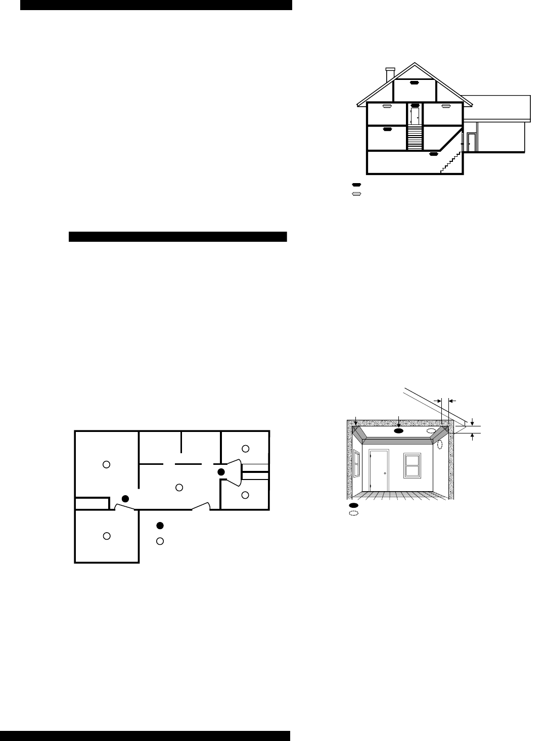
νPut a smoke alarm on every level of a multi-level
residence (Figure 5).
νInstall basement alarms on the ceiling at the bot-
tom of the basement stairwell.
Figure 2. Multi-level residence.
νInstall smoke alarms on the ceiling as close to the
center of the room as possible. If this is not practi-
cal, install it on the ceiling no closer than 4 inches
(10 cm) from any wall or corner (Figure 6).
νIf ceiling mounting is not practical, install on an
inside wall between 4 and 6 inches (10 and 15 cm)
from the ceiling (Figure 6).
νPut smoke alarms at both ends of a bedroom hall-
way if the hallway is more than 30 feet (9 meters)
long. Large rooms over 900 square feet require
more than a single sensor.
Figure 3. Smoke alarm mounting locations.
νAreas with rough ceilings or short, transom-type
walls coming down from the ceiling require addi-
tional smoke alarms.
νInstall second-floor smoke alarms on the ceiling at
the top of the first-to-second floor stairwell. Be
sure no door or other obstruction blocks the path
of smoke to the unit.
νIn rooms with sloped, peaked, or gabled ceilings,
install smoke alarms 3 feet (0.9 meter) measured
down on the slant from the highest point of the
ceiling (Figure 7).
BEDROOM
SMOKE DETECTORS FOR
MINIMUM PROTECTION
SMOKE DETECTORS FOR
MORE PROTECTION AND
REQUIRED IN NEW CONSTRUCTION
BEDROOM
BEDROOM
LIVING ROOM
DINING
ROOM
KITCHENFAMILY ROOM
BEDROOM
BEDROOM BEDROOM
LIVING
ROOM
KITCHEN
BASEMENT
GARAGE
SMOKE DETECTORS FOR MINIMUM PROTECTION
SMOKE DETECTORS FOR MORE PROTECTION AND
REQUIRED IN NEW CONSTRUCTION
BEST LOCATION
ACCEPTABLE LOCATION
DEAD AIR
SPACE BEST IN CENTER
OF CEILING
NO CLOSER THAN 4
"
(10 cm)
FROM SIDE WALL
MOUNT ON WALL
AT LEAST 4
"
(10 cm)
FROM CEILING
NO MORE
THAN 6
"
(15 cm)
FROM CEILING

System Sensor Smoke Sensor
Page 3
Figure 4. Sloped, peaked, or gabled ceilings.
Do not install smoke alarms in the following loca-
tions:
νIn or near areas where combustion particles are
normally present such as kitchens; in garages
where there are particles of combustion in vehicle
exhausts; near furnaces, hot water heaters, or gas
space heaters.
νOn the ceiling in rooms next to kitchens where
there is no transom between the kitchen and these
rooms.
νIn damp or very humid areas, or next to bath-
rooms with showers. Install sensors at least 5 feet
(1.5 meters) away from bathrooms.
νIn very cold or very hot areas.
νIn dusty, dirty, or insect-infested areas.
νNear fresh air inlets or returns or excessively
drafty areas. Air conditioners, heaters, fans, and
fresh air intakes and returns can drive smoke
away from smoke alarms.
νIn dead air spaces at the top of a peaked ceiling or
wall/ceiling intersect. Dead air may prevent
smoke from reaching a smoke alarm.
νNear fluorescent light fixtures. Install smoke
alarms at least 10 feet (3 meters) away from fluo-
rescent light fixtures.
Mounting
The mounting bracket must be separated from the unit
before you begin.
To mount the smoke alarm:
1. Secure the mounting bracket directly onto wood
surfaces using No. 8, 1½ inch wood screws. If
mounting onto plaster or dry wall, use appropri-
ate anchors.
2. Align the arrows on the mounting bracket with
the raised marks on the smoke alarm. Turn the
smoke alarm clockwise until it locks in place.
Testing
Test each smoke alarm every week to verify that its
siren and signal integrity are adequate.
To test the smoke alarm:
1. Put the panel in sensor test mode. Refer to the
panel’s installation manual for details.
Note: To avoid a fire department dispatch from the
central station, make sure the panel is in sen-
sor test mode before testing.
2. Use a pencil or small screwdriver to press and
hold the test button on the smoke alarm for 5 sec-
onds (Figure 1).
The sensor should immediately send an alarm signal
to the panel, causing it to beep up to 16 times, or by
sounding one high-pitch beep from system sirens
(refer to the panel’s installation manual for response
details).
After 2.5 seconds, the siren inside the smoke alarm
sounds and the status light flashes rapidly.
Maintaining the Smoke Alarm
Batteries
The 3-volt lithium batteries may last as much as 5
years before they need to be replaced.
Replace both batteries when the smoke alarm or panel
notifies you that the batteries are low.
Cleaning the Smoke Alarm Chamber
Clean the smoke alarm chamber at least once each
year.
To clean the smoke alarm chamber:
1. Place the panel in sensor test mode.
2. Remove the batteries. Do not remove the skirt.
3. Follow the instructions in the section “Removing
the Shorting Blocks” to remove the cover and the
screen.
4. Vacuum both the screen and the smoke chamber.
HORIZONTAL
DISTANCE
FROM PEAK
3 FEET
(.9M)

Page 4
System Sensor Smoke Sen-
Specifications
Compatibility:
Dimensions:
Operating Temperature Range: 32° (0°C) to 100°F
(38°C).
Power Source: Two 3-volt lithium batteries of the
same type. UL-approved types: Sanyo CR123A, Pana-
sonic CR123A, Duracell DL123A.
Notices
Agency Listings: UL 268—Residential Installations
NFPA 72, Chapter 2, Section 2-2.1.1.1 states as follows: “Smoke sensors shall be
installed outside of each separate sleeping area in the immediate vicinity of the bed-
rooms and on each additional story of the family living unit, including basements and
excluding crawl spaces and unfinished attics. In new construction, a smoke sensor also
shall be installed in each sleeping room.”
The above NFPA standard is a minimum requirement for smoke sensor installation. For
better protection, we also require the installation of a smoke sensor inside every bed-
room in existing construction.
This device complies with part 15 of the FCC rules. Operation is subject to the following
two conditions:
1) This device may not cause harmful interference.
2) This device must accept any interference received, including interference that may
cause undesired operation.
Changes or modifications not expressly approved by Interactive Technologies, Inc. can
void the user’s authority to operate the equipment.
FCC Registratio No.: B4Z764A-SMOKE
ITI is a registered trademark of Interactive Technologies, Inc. System Sensor is a trade-
mark of System Sensor.
651/777-2690
651/779-4890