UTC Fire and Security Americas 785B-ALGRO Security Panel User Manual
UTC Fire & Security Americas Corporation, Inc. Security Panel
UserManual.wiki
>
UTC Fire and Security Americas
>
785B ALGRO User Manual
Install Manual
Navigation menu
Upload a User Manual
Namespaces
Wiki Guide
HTML
PDF
Info
Views
User Manual
Discussion / Help
Navigation
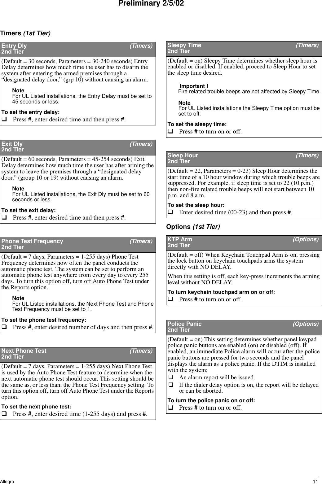
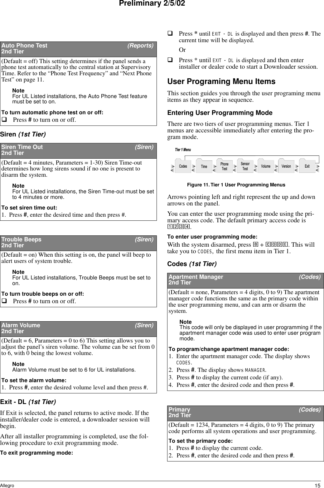
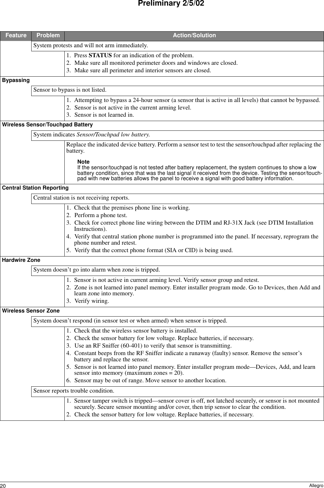
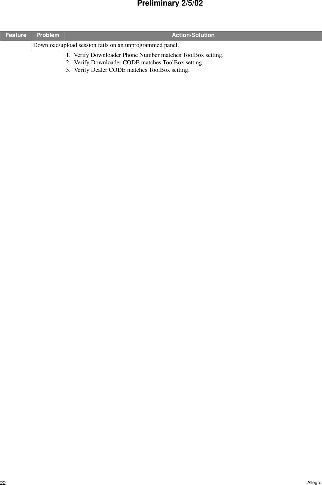
![21AllegroPreliminary 2/5/02Wireless Sensor Zone (Continued)Panel indicates [sensor #] supervisory.1. Use an RF Sniffer (60-401) to verify that sensor is transmitting. If sensor is not transmitting, check battery for low or no voltage and replace.2. Change mounting position of sensor (from horizontal to vertical or vice versa) and test sensor several times for consistency.3. Sensor signal is not reaching panel/receiver because sensor is too far away or there is too much inter-ference. Remove sensor from mounted location and test from other locations. Mount sensor in area where signal can reach panel/receiver.Smoke sensor beeps once every minute.Sensor batteries are getting low. Replace batteries.Note System Sensor smoke sensors do not transmit a low battery signal to the panel/receiver until battery voltage drops to within a range of 7.0 to 7.8 VDC. The sensor sounds beeps to notify occupants that the sensor’s batteries need replacing, but the sensor does not transmit a low battery signal to the panel until the next supervisory signal (69 minutes later).Wireless TouchpadSystem doesn’t respond to commands entered from wireless touchpad.❑Check for dead batteries.❑Perform a sensor test.Touchpad reports trouble condition.Check the touchpad battery for low voltage. Replace battery, if necessary.DTIMPanel displays phone module memory failure, or Service required.1. Perform a sensor test.2. Call technical support for assistance.Panel displays Phone Module Low Battery.1. Replace the battery and perform a sensor test.2. Call technical support.PhoneConstant dial tone, preventing dial-out on premises phones.One or more polarity-sensitive phones exist on-site. Panel displays phone 1 fail, phone 2 fail, or phone failure.1. Perform a phone test.2. Check to make sure manual phone test option is on.3. Verify that high and/or low level reporting option is on.4. Perform a sensor test to verify communication between the DTIM and panel. See Phone Test (Reports) on page 145. Check DTIM wiring (see DTIM installation instructions).Phone TestPanel does not display option to perform a phone test.❑The central station phone number is not programmed in.❑DTIM has not been enrolled.DownloaderDownload/upload session fails on a pre-programmed panel.1. Verify Downloader Phone Number matches ToolBox setting.2. Verify Downloader CODE matches ToolBox setting.3. Verify Dealer CODE matches ToolBox setting.4. Verify panel Account Number matches ToolBox setting.Feature Problem Action/Solution](https://usermanual.wiki/UTC-Fire-and-Security-Americas/785B-ALGRO/User-Guide-224640-Page-23.png)