UTC Fire and Security Americas 824-DWS 900MHz Door/Window Sensor User Manual
UTC Fire & Security Americas Corporation, Inc. 900MHz Door/Window Sensor
UserManual.wiki
>
UTC Fire and Security Americas
>
824 DWS User Manual
Installation Manual
Navigation menu
Upload a User Manual
Namespaces
Wiki Guide
HTML
PDF
Info
Views
User Manual
Discussion / Help
Navigation
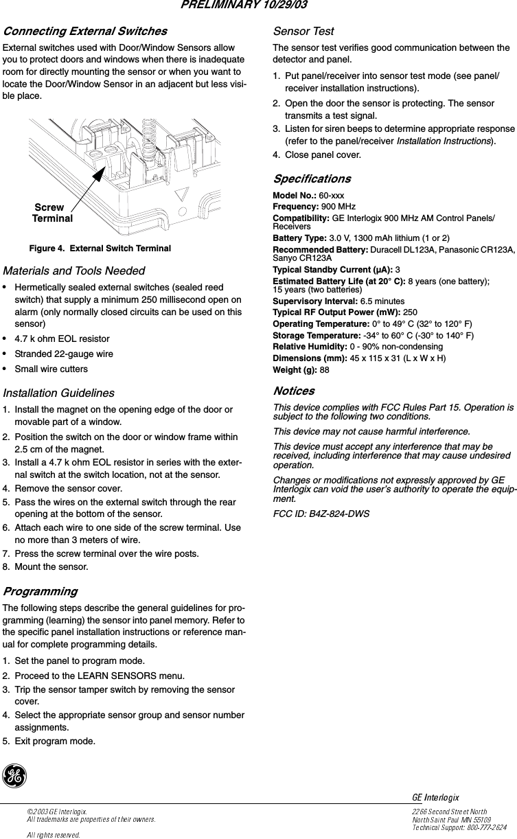
![1,QVWDOODWLRQ,QVWUXFWLRQV*(,QWHUORJL['Product InformationThe sensor can be installed on doors, windows, and many other objects that open and close. The sensors transmit sig-nals to the Control Panel when a magnet mounted near the sensor is moved away from or closer to the sensor. The 900 MHz Long-Life Door/Window Sensor is equipped with a wall and cover tamper for additional security. Extend the battery life of the sensor by adding a second 3-volt lithium battery.Installation GuidelinesUse the following guidelines for installing Door/Window sen-sors.•Mount the sensor on the door frame and the magnet on the door. If the sensor is to be used on double doors, mount the sensor on the least-used door and the magnet on the other door.•If possible, locate sensors within 30 meters of the panel. While a transmitter may have a range of 150 meters or more out in the open, the environment at the installation site can have a significant effect on transmitter range. Sometimes a change in sensor location can help over-come adverse wireless conditions.•Make sure the alignment arrow on the magnet points to the alignment mark on the sensor.•Place sensors at least 12 cm above the floor to avoid damaging them.•Avoid mounting sensors in areas where they will be exposed to moisture or where the operating temperature (0° to 49° C) will be exceeded.Materials Needed•#6 flathead screws•Screwdriver or brad driverVerify Programming and Sensor-to-Panel RF CommunicationBefore mounting, verify the desired detector location pro-vides good RF communication to the panel.1. Put panel/receiver into sensor test mode.2. Take sensor to desired mounting location.3. Trip the sensor. The sensor transmits a test signal.4. Listen for siren beeps to determine appropriate response (refer to the panel/receiver Installation Instructions).5. Exit sensor test mode.To install Door/Window sensors:1. Remove the sensor cover by pressing a small screw-driver into the slot on the end of the sensor while lifting the cover.NoteIf you need to connect external switches, they should be installed at this point. See the procedure for connecting external switches in this docu-ment.2. Mount the sensor base with two #6 flathead screws at the locations shown in Figure 2. Figure 2. Mounting the Sensor and Magnet3. Remove the magnet from its base. Line up the arrow on the magnet with the mark on the narrow end or side of the sensor.4. Mount the magnet base no more than 1 cm away from the sensor base. Replace the magnet cover.5. Install the tamper switch as shown in Figure 36. Attach the sensor cover to the sensor baseFigure 3. Installing Tamper SwitchFigure 1. Opening the Sensor CoveMounting HolesDoor Door Frame1 cm OR120+]'RRU:LQGRZ6HQVRUDocument No. 466-2xxx Rev. AOctober 2003PRELIMINARY 10/29/03](https://usermanual.wiki/UTC-Fire-and-Security-Americas/824-DWS/User-Guide-474336-Page-1.png)