UTC Fire and Security Americas 824-DWS 900MHz Door/Window Sensor User Manual
UTC Fire & Security Americas Corporation, Inc. 900MHz Door/Window Sensor
Installation Manual
1
,QVWDOODWLRQ,QVWUXFWLRQV
*(,QWHUORJL[
'
Product Information
The sensor can be installed on doors, windows, and many
other objects that open and close. The sensors transmit sig-
nals to the Control Panel when a magnet mounted near the
sensor is moved away from or closer to the sensor. The 900
MHz Long-Life Door/Window Sensor is equipped with a wall
and cover tamper for additional security. Extend the battery
life of the sensor by adding a second 3-volt lithium battery.
Installation Guidelines
Use the following guidelines for installing Door/Window sen-
sors.
•Mount the sensor on the door frame and the magnet on
the door. If the sensor is to be used on double doors,
mount the sensor on the least-used door and the magnet
on the other door.
•If possible, locate sensors within 30 meters of the panel.
While a transmitter may have a range of 150 meters or
more out in the open, the environment at the installation
site can have a significant effect on transmitter range.
Sometimes a change in sensor location can help over-
come adverse wireless conditions.
•Make sure the alignment arrow on the magnet points to
the alignment mark on the sensor.
•Place sensors at least 12 cm above the floor to avoid
damaging them.
•Avoid mounting sensors in areas where they will be
exposed to moisture or where the operating temperature
(0° to 49° C) will be exceeded.
Materials Needed
•#6 flathead screws
•Screwdriver or brad driver
Verify Programming and Sensor-to-Panel RF
Communication
Before mounting, verify the desired detector location pro-
vides good RF communication to the panel.
1. Put panel/receiver into sensor test mode.
2. Take sensor to desired mounting location.
3. Trip the sensor. The sensor transmits a test signal.
4. Listen for siren beeps to determine appropriate response
(refer to the panel/receiver Installation Instructions).
5. Exit sensor test mode.
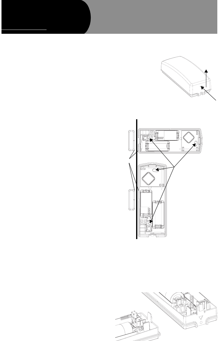
To install Door/Window sensors:
1. Remove the sensor cover by pressing a small screw-
driver into the slot on the end of the sensor while lifting
the cover.
Note
If you need to connect
external switches,
they should be
installed at this point.
See the procedure for
connecting external
switches in this docu-
ment.
2. Mount the sensor
base with two #6
flathead screws at the locations shown in Figure 2.
Figure 2. Mounting the Sensor and Magnet
3. Remove the magnet from its base. Line up the arrow on
the magnet with the mark on the narrow end or side of
the sensor.
4. Mount the magnet base no more than 1 cm away from
the sensor base. Replace the magnet cover.
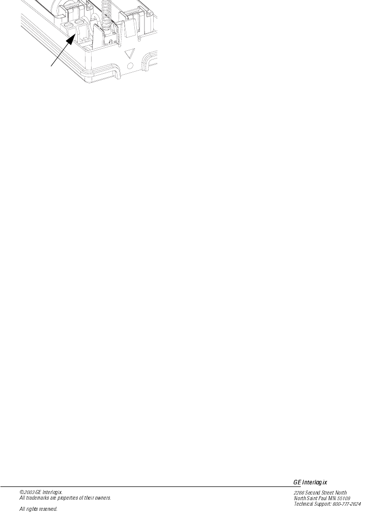
5. Install the tamper switch as shown in Figure 3
6. Attach the sensor cover to the sensor base
Figure 3. Installing Tamper Switch
Figure 1. Opening the Sensor Cov
e
Mounting Holes
Door Door Frame
1 cm OR
1
2
0+]'RRU:LQGRZ
6HQVRU
Document No. 466-2xxx Rev. A
October 2003
PRELIMINARY 10/29/03
2
PRELIMINARY 10/29/03
Connecting External Switches
External switches used with Door/Window Sensors allow
you to protect doors and windows when there is inadequate
room for directly mounting the sensor or when you want to
locate the Door/Window Sensor in an adjacent but less visi-
ble place.
Figure 4. External Switch Terminal
Materials and Tools Needed
•Hermetically sealed external switches (sealed reed
switch) that supply a minimum 250 millisecond open on
alarm (only normally closed circuits can be used on this
sensor)
•4.7 k ohm EOL resistor
•Stranded 22-gauge wire
•Small wire cutters
Installation Guidelines
1. Install the magnet on the opening edge of the door or
movable part of a window.
2. Position the switch on the door or window frame within
2.5 cm of the magnet.
3. Install a 4.7 k ohm EOL resistor in series with the exter-
nal switch at the switch location, not at the sensor.
4. Remove the sensor cover.
5. Pass the wires on the external switch through the rear
opening at the bottom of the sensor.
6. Attach each wire to one side of the screw terminal. Use
no more than 3 meters of wire.
7. Press the screw terminal over the wire posts.
8. Mount the sensor.
Programming
The following steps describe the general guidelines for pro-
gramming (learning) the sensor into panel memory. Refer to
the specific panel installation instructions or reference man-
ual for complete programming details.
1. Set the panel to program mode.
2. Proceed to the LEARN SENSORS menu.
3. Trip the sensor tamper switch by removing the sensor
cover.
4. Select the appropriate sensor group and sensor number
assignments.
5. Exit program mode.
Sensor Test
The sensor test verifies good communication between the
detector and panel.
1. Put panel/receiver into sensor test mode (see panel/
receiver installation instructions).
2. Open the door the sensor is protecting. The sensor
transmits a test signal.
3. Listen for siren beeps to determine appropriate response
(refer to the panel/receiver Installation Instructions).
4. Close panel cover.
Specifications
Model No.: 60-xxx
Frequency: 900 MHz
Compatibility: GE Interlogix 900 MHz AM Control Panels/
Receivers
Battery Type: 3.0 V, 1300 mAh lithium (1 or 2)
Recommended Battery: Duracell DL123A, Panasonic CR123A,
Sanyo CR123A
Typical Standby Current (µA): 3
Estimated Battery Life (at 20° C): 8 years (one battery);
15 years (two batteries)
Supervisory Interval: 6.5 minutes
Typical RF Output Power (mW): 250
Operating Temperature: 0° to 49° C (32° to 120° F)
Storage Temperature: -34° to 60° C (-30° to 140° F)
Relative Humidity: 0 - 90% non-condensing
Dimensions (mm): 45 x 115 x 31 (L x W x H)
Weight (g): 88
Notices
This device complies with FCC Rules Part 15. Operation is
subject to the following two conditions.
This device may not cause harmful interference.
This device must accept any interference that may be
received, including interference that may cause undesired
operation.
Changes or modifications not expressly approved by GE
Interlogix can void the user’s authority to operate the equip-
ment.
FCC ID: B4Z-824-DWS
Screw
Termin al
)