UTC Fire and Security Americas 839-TWTP Two Way RF Touch Pad User Manual
UTC Fire & Security Americas Corporation, Inc. Two Way RF Touch Pad
Users Manual
1
,QVWDOODWLRQ,QVWUXFWLRQV
*(6HFXULW\
'
Product
Summary
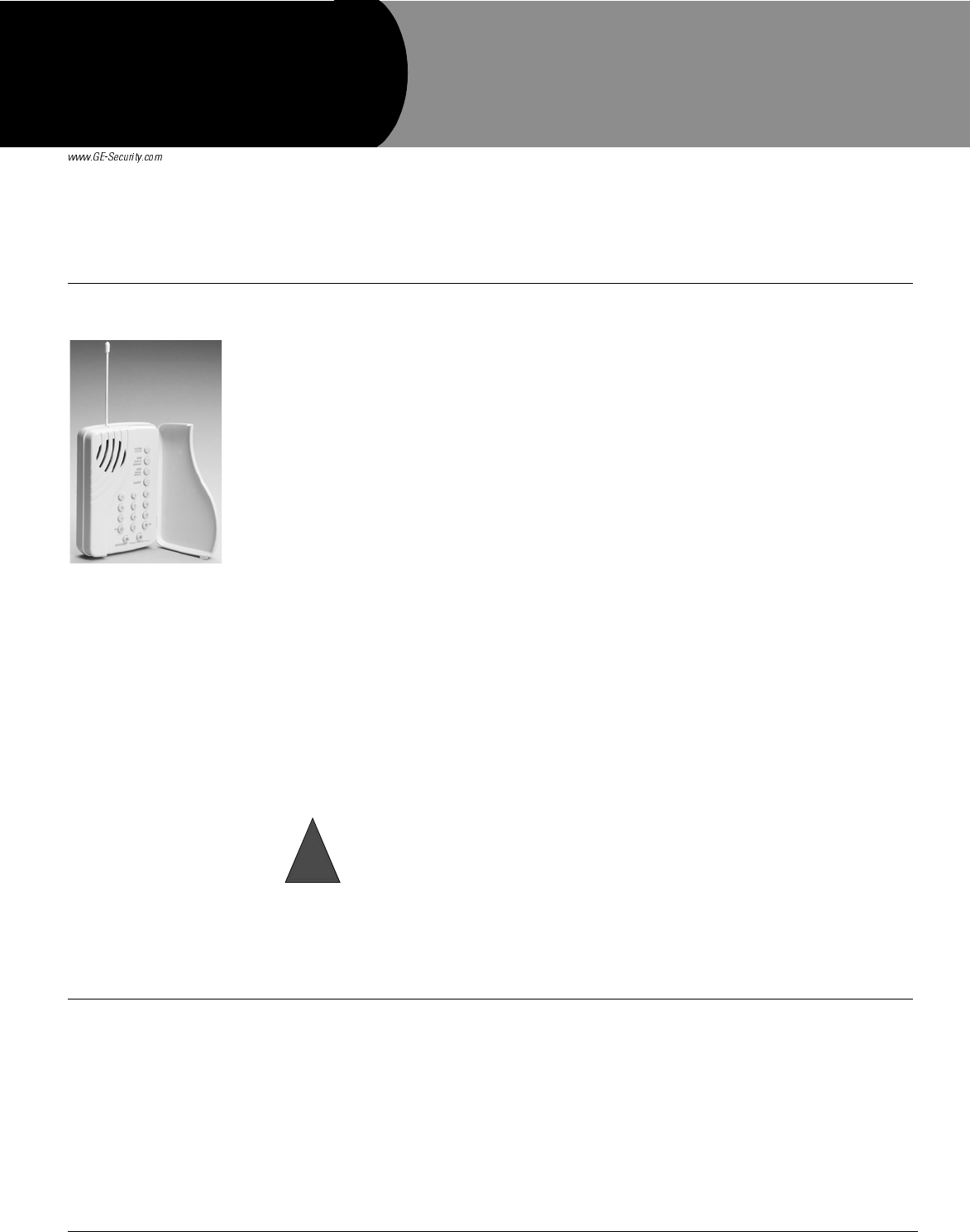
The wall-mounted wireless Dialog QS1500 Touchtalk Interactive Keypad combines a conven-
tional Learn Mode™ keypad with an RF receiver, speech chip, and voice amplification circuit for
your Simon 3 ® security system.
The QS1500 Touchtalk Interactive Keypad is an alkaline battery-powered, wireless keypad
designed to provide users a convenient option for the following system operations:
• Arm the system (doors, windows, and motion sensors).
• Arm the system with No Entry Delay.
• Disarm the system.
• Activate a panic alarm to call the central monitoring station in a non-medical emergency.
• Check system status.
• Turn system controlled lights on or off (all or individual).
• Enables the user to hear the voice feedback that is heard at the Simon 3 Control Panel.
The keypad has two operating modes: key and chime.
In key mode, voice feedback is heard only at the keypad when a system command is entered.
Examples of this would be: system status, arming and disarming. In this mode the keypad does
not repeat siren sounds and will not make any alarm sounds or status beeps. This feature extends
battery life to the keypad and gives feedback only to the user who needs it. When the keypad is
in key mode it is compatible with Simon 3 panels version 3.3 and newer.
In chime mode, all voice feedback that is heard in key mode, plus, trouble beeps, entry/exit
beeps and alarm sounds (Fire, Aux, Police) are heard at the keypad. The keypad will also
respond to panel broadcast messages at multiple keypads. While in chime mode the keypad can
be supervised and will send supervision messages to the panel. In chime mode the keypad is
compatible with Simon 3 panels version 4.0 and newer
Voice feedback depends on how Simon 3 panel options 41 and 87 are set. See the Simon 3 Instal-
lation Instructions (466-1873) for more information.
Voice feedback is heard at all keypads. If the keypad is talking, the panel is silent. When the
panel is talking, the keypad is silent.
The keypad has no tamper detection. A low battery condition is automatically detected by the
keypad and communicated to the control panel.
Installation Installation of the QS1500 Touchtalk Interactive Keypad includes guidelines for installing, pro-
gramming, sensor testing, improving sensor communication and mounting the keypad.
Installation Guidelines
Use the following guidelines when adding this keypad to your Simon 3 system:
• Program the keypad as key or chime mode.
• Keypads are learned into the control panel as sensors.
Part No. 60-924-01-3
The keypad has limited audio power. Therefore, the keypad should not be relied on for
alarm announcements and is no substitute for an alarm siren.
Warning
!
'RFXPHQW1XPEHU5HY$
-XQH
'LDORJ467RXFKWDON
,QWHUDFWLYH.H\SDG

2Dialog QS1500 Touchtalk Interactive Keypad Installation Instructions
• Key mode keypads should be programmed using sensor groups 01, 03, 06, or 07 for non
supervised use.
• Chime mode keypads can be programmed using sensor groups 01, 03, 06 or 07 for non
supervised use or sensor groups 00, 02, 04 or 05 for supervised use.
• The keypad must be deleted and reprogrammed into panel memory every time the key-
pad operating mode is changed.
• Each learned keypad uses one of the available sensor numbers (24 total sensors/zones
can be used with the Simon 3 panel).
• When the keypad is mounted on the wall, it might not work properly if mounted too
close to the Simon 3 panel.
Programming
For complete programming instructions, refer to your Simon 3 installation instructions. The
keypad must be programmed for key or chime mode before programming into panel mem-
ory.
¾To program the keypad mode:
1. Remove the mounting plate on the back of the keypad.
2. Insert two of the three batteries into the keypad.
Note
To check the software ver-
sion of the keypad, press 1
after Step 3.
3. While holding down the Lights On and Lights Off keys, insert the third battery. Release
the keys. The keypad will sound one long beep.
4. Immediately press 8 to program the keypad for key mode. The keypad announces “No
chime hello, touchpad OK”. OR Press 9 to program the keypad for chime mode. The
keypad announces “Chime hello, touchpad OK”.
Note
The “Chime” and “No chime” announcements from the keypad only describe the keypad mode
being programmed. The announcements don’t describe doors and special motion chime functions
programmed at the panel.
After programming the mode, the keypad must be programmed into the panel.
¾To program the keypad into panel memory:
1. Open the control panel cover.
2. Enter Utility Access Code 1 or 2 using the red numbered keys.
3. Press Add. The panel announces “Select from Main Menu.”
4. Press Sensor/Remote. The panel announces “Press button on sensor.”
Note
If the keypad doesn’t
announce “OK”, press Can-
cel at the panel and repeat
process starting from Step 3.
5. Press the Lights Off button on the keypad six times in rapid succession. On the sixth key
press the keypad makes a long beep. The keypad announces “OK”, to indicate that it has
been learned into the panel. Panel announces keychain remote.
Note
For a more specific location
name, press Option # for
compass directions (north,
northeast, east, southeast,
south, southwest, west,
northwest).
6. Press Sensor/Remote repeatedly until you hear the sensor name or item you want to use.
Each name may be used more than once.
7. Press DONE when you hear the desired sensor name. The panel announces “Use num-
bered keys to enter sensor group.”
Note
If you wish to use a sensor
number other than the next
one available, use the num-
bered keys to enter a 2 digit
sensor number immediately
after entering the sensor
group.
8. Enter the 2-digit sensor group (Key mode: 01, 03, 06 or 07 OR Chime mode: 00 through
07). The panel announces the sensor group and the first available sensor number, then
prompts you to press DONE to accept.
9. Press DONE. The panel confirms programming by announcing the sensor number,
name, and group.
Performing a Sensor Test
The keypad is sensitive to its orientation to the control panel. For that reason, it is recom-
mended that you test the keypad prior to mounting it on the wall.
The following steps describe the guidelines for testing sensors used in a Simon 3 system.
1. Make sure the panel is disarmed.
2. Open the panel cover.
3. Enter the appropriate access code.
3Dialog QS1500 Touchtalk Interactive Keypad Installation Instructions
4. Press Test.
The panel responds with Sensor test, press again to change or DONE to select.
5. Press DONE.
Note
To verify the communication
between the panel and the
keypad, close the panel’s
cover to put the panel in run
mode. Press the SYSTEM
STATUS button on the key-
pad. The keypad should
announce the correct sys-
tem status (i.e. “System Dis-
armed”).
The panel will prompt you to trip each sensor one at a time. To trip the keypad, press and hold the
two Emergency buttons simultaneously for three seconds. You may follow the panel voice
prompting or test the sensors in any order. Use the “Sensor Tripping Instructions” table in your
Simon 3 Installation Manual to trip sensors.
We recommend that you test the keypad after all programming is completed and whenever a key-
pad-related problem occurs.
If a Keypad Fails a Sensor Test
If panel sirens do not beep when a keypad is tripped, use a GE Security RF Sniffer (60-401) test
tool to verify that the keypad is transmitting. Constant beeps from the RF Sniffer indicate a run-
away (faulty) keypad. Two or three beeps from the RF Sniffer indicates the keypad is functional,
but may have to be relocated. If the keypad is faulty, replace it.
How to Improve Sensor Communication
• Relocate the keypad.
• If necessary, replace the keypad.
¾To Relocate a Keypad:
1. Test the keypad a few inches from the original position.
2. Increase the distance from the original position. Retest until an acceptable location is found.
3. Mount the keypad in the new location (see Mounting the Keypad section).
4. If no location is acceptable, replace the keypad.
¾To Replace a Keypad:
1. Test a known good keypad at the same location.
2. If transmission beeps remain below the minimum level, avoid mounting a keypad at the loca-
tion.
3. If the replacement keypad functions, contact GE Security for repair or replacement of the
problem keypad.
Mounting the Keypad
To mount the keypad on a wall, do the following:
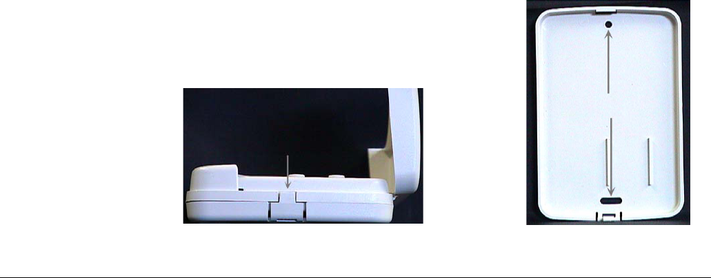
1. Open the door of the keypad.
2. Gently pull down on the tab at the bottom of the keypad to separate the keypad body from the
keypad mounting plate (Figure 1).
3. Hold the keypad mounting plate against the wall. Using the two screws included with the key-
pad, attach the keypad mounting plate to the wall through the mounting holes (Figure 2).
Figure 1. Keypad Bottom View Figure 2. Keypad Mounting Plate
Mounting Holes
Tab
4Dialog QS1500 Touchtalk Interactive Keypad Installation Instructions
4. Reattach the keypad to the mounting plate.
Testing the Keypad After Mounting
Note
While the sensor test is a
valuable installation and ser-
vice tool, it only tests sensor
operation for the current
conditions. You should per-
form a sensor test after any
change in environment,
equipment, or programming.
Repeat the steps listed in the “Performing a Sensor Test” section in this manual.
Keypad Operation
• Numeric Buttons (0 - 9) - Used to enter an access code or turn individual lights on and off.
• Disarm Button - The control panel is disarmed to level 0 or 1. (Level 0 all sensors except
smoke alarms are disarmed. Level 1 doors, windows, and motion sensors are disarmed). Dis-
arm also requires the access code to be entered.
• ARM Doors & Windows Button - The control panel is armed to level 2.
• ARM Motion Sensors Button - The control panel is armed to level 3. If the ARM Doors &
Windows button was previously pressed, the control panel is armed to level 4 (Doors/Win-
dows and Motion Sensors armed).
• Lights On Button - Pressing this button twice quickly turns on all lights controlled by the sys-
tem. Pressing this button once plus 1-8 will turn on that individual numbered light.
• Lights Off Button - Pressing this button twice quickly turns off all lights controlled by the sys-
tem. Pressing this button once plus 1-8 will turn off that individual numbered light.
• Emergency Buttons - The panel will react according to the sensor group they are learned in to
(00-07) Intrusion, Silent or Emergency. Press and hold both keys OR press both keys twice
quickly, to activate alarm reports to the central station.
Battery Replacement
When the batteries get low on the keypad, the keypad announces “Touchpad low battery”. The
panel announces “<Sensor name> low battery”.
Note
Avoid pressing the buttons
on the keypad during battery
replacement.
Remove the touchpad from the mounting plate and replace all three batteries with AAA alkaline
batteries.
After replacing the batteries, run a sensor test to realign the keypad to the panel.
Specifications Compatibility: ..........................Simon 3 (version 3.3 and later)
Power Requirements: ..............3 AAA Alkaline batteries
Storage Temperature: ..............-40° to 140° F (-34° to 60° C)
Operating Temperature: .........32° to 120° F (0° to 49° C)
Maximum Humidity:...............90% relative humidity, non-condensing
Dimensions: ..............................3.6 x 1.2 x 5.4 in. (W x D x H)
Installation: ..............................Wall mounting
Listings:
FCC Notice
1. This device may not cause harmful interference.
2. This device must accept any interference that may be received, including interference that may cause undesired
operation.
Notices
)
*(6HFXULW\