UTC Fire and Security Americas 910C-SIMON GE Simon XT User Manual simonxt iman
UTC Fire & Security Americas Corporation, Inc. GE Simon XT simonxt iman
UserManual.wiki
>
UTC Fire and Security Americas
>
910C SIMON User Manual
Manual
Navigation menu
Upload a User Manual
Namespaces
Wiki Guide
HTML
PDF
Info
Views
User Manual
Discussion / Help
Navigation

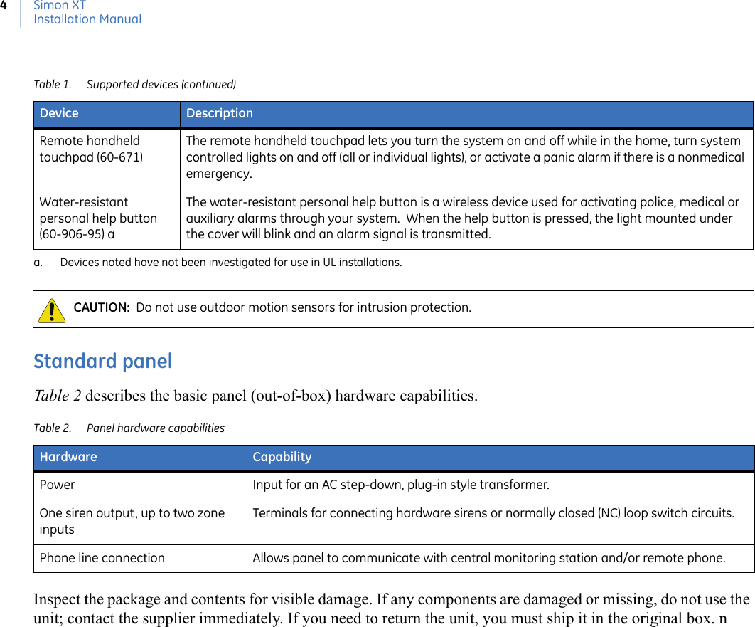
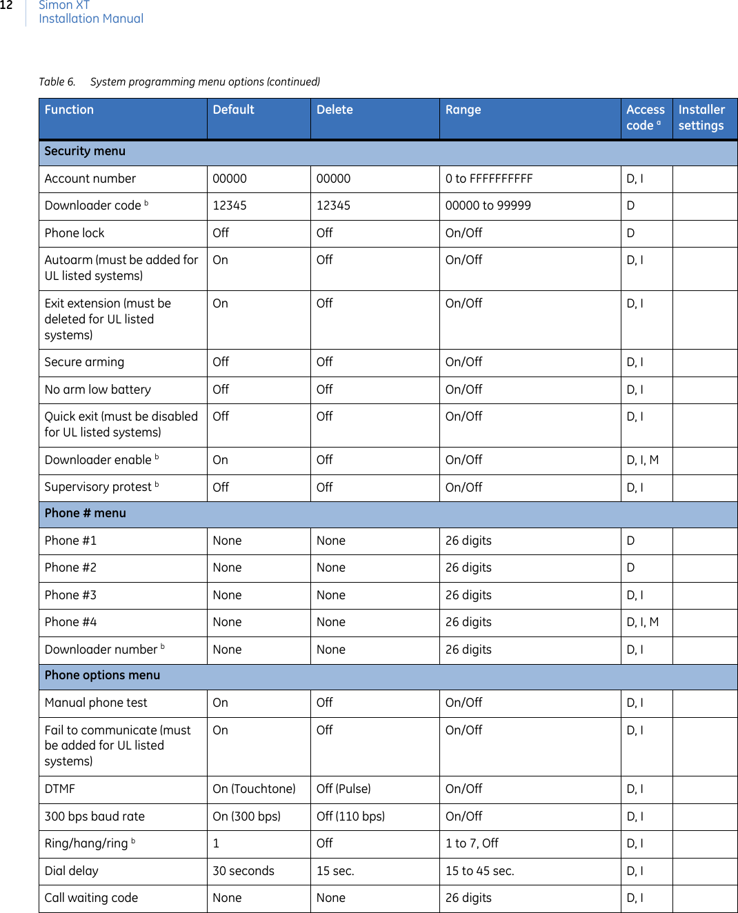
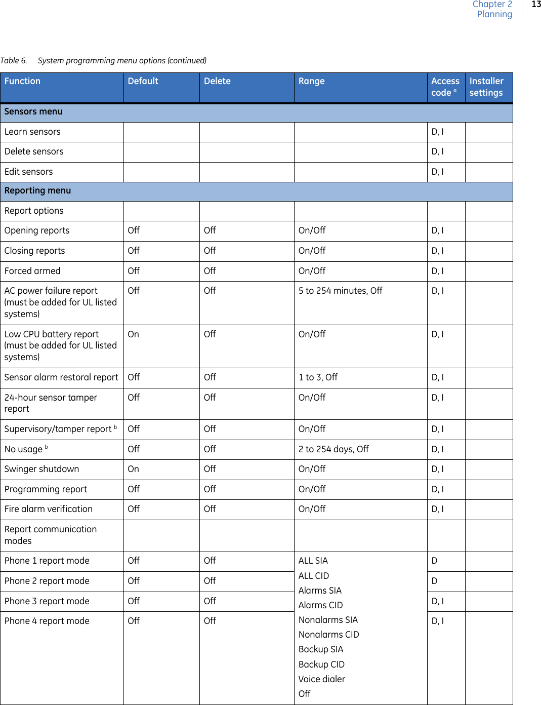
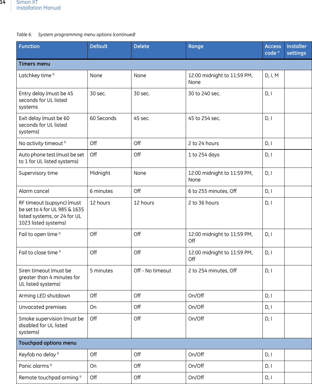
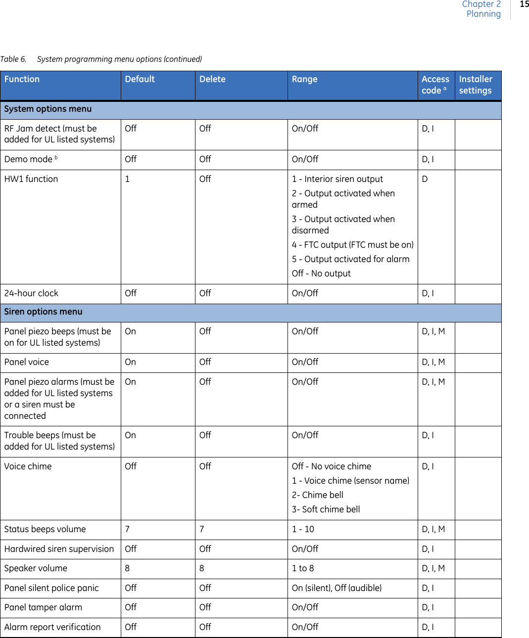
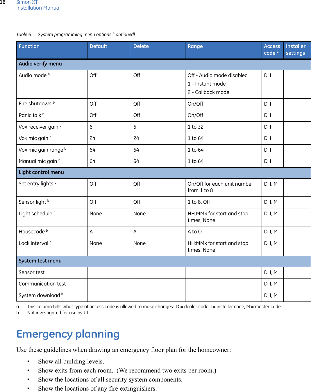
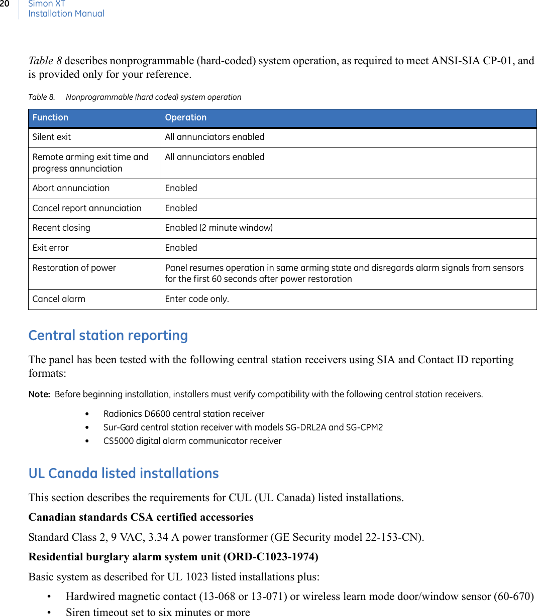
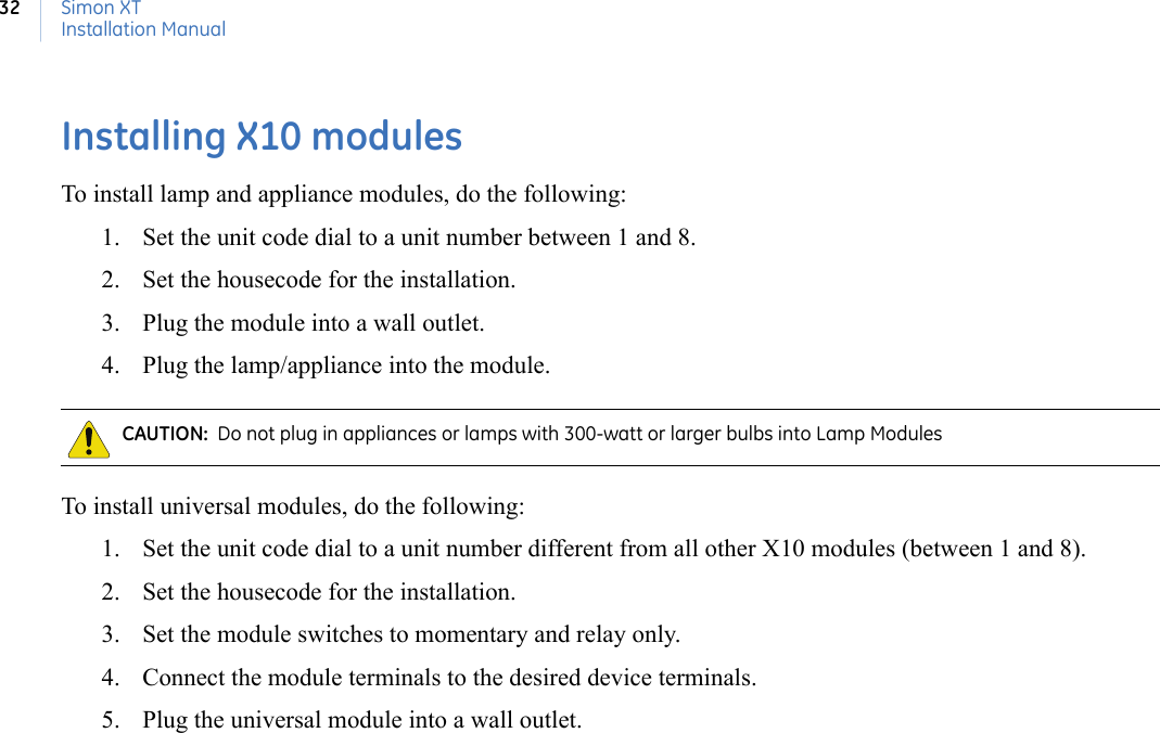
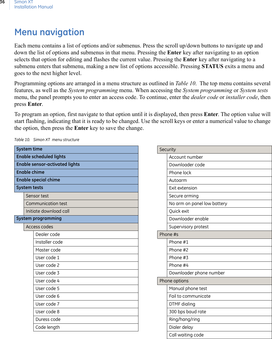
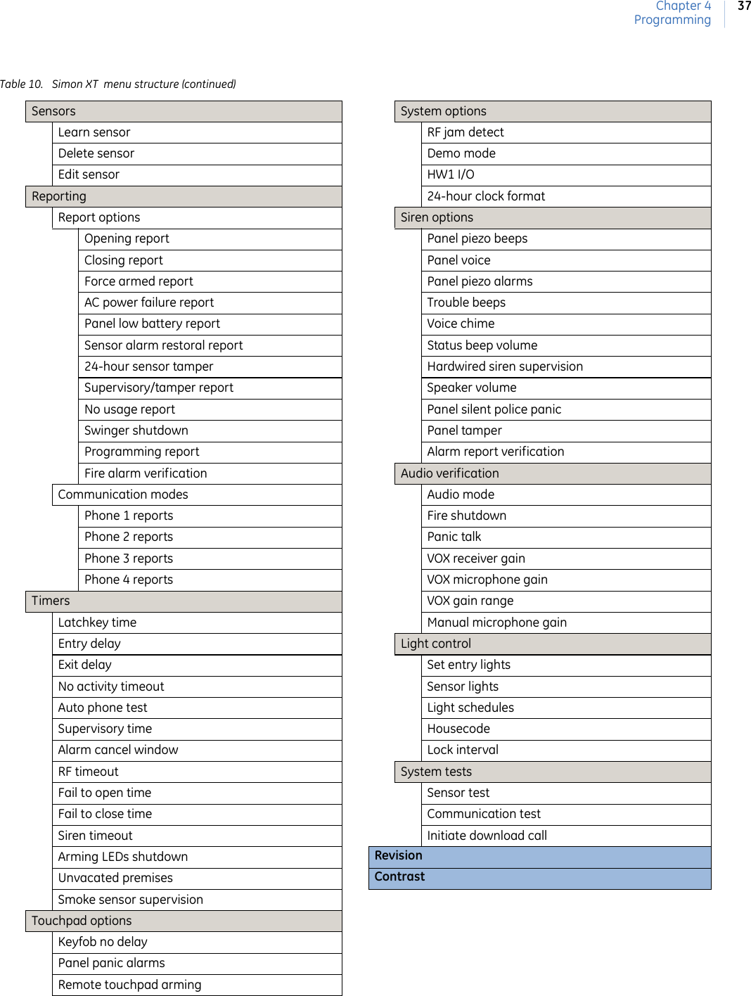
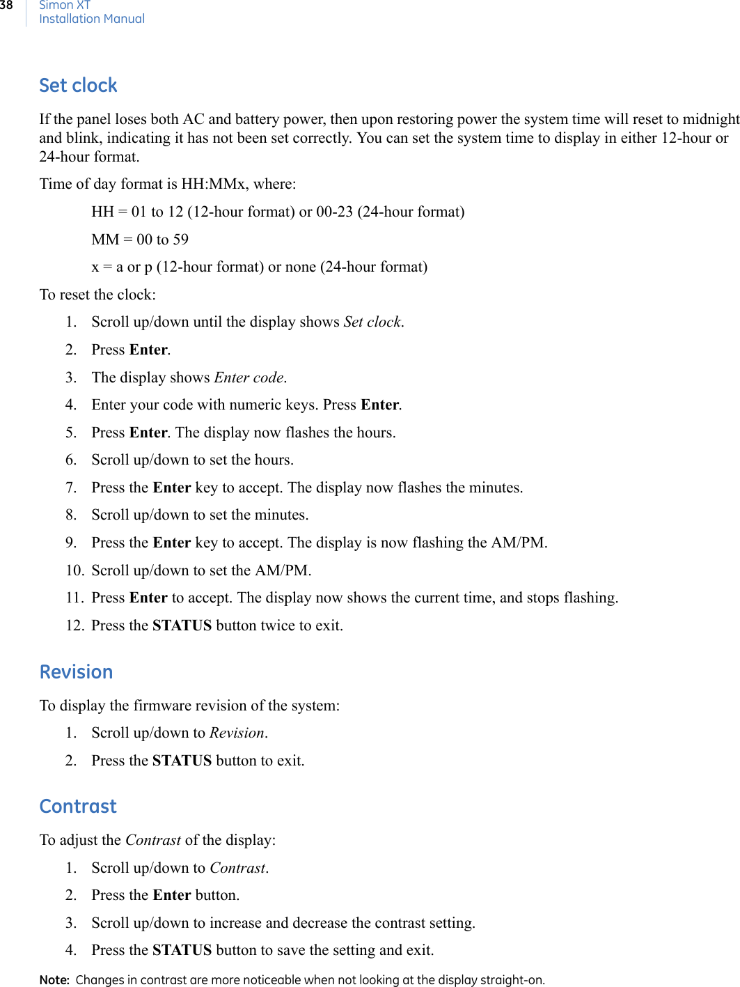
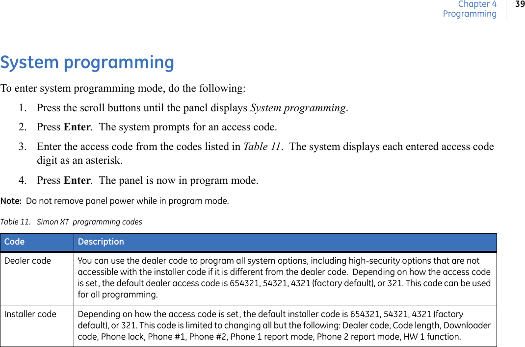
![73Table 39. Sensor name segments by index number (in scrolling order) #Phrase000 Keyfob (keychain)001 Touchpad002 Front door003 Front window004 Back door005 Back window006 Garage door007 Garage window008 Master bedroom009 Master bedroom window010 Bedroom011 Bedroom window012 Guest room013 Guest room window014 Child’s room015 Child’s room window016 Utility room017 Living room018 Living room window019 Kitchen020 Kitchen window021 Porch022 Porch window023 Patio door024 Office025 Office window026 Den027 Den window028 Garage029 Special chime030 Basement031 Basement window032 Upstairs033 Upstairs window034 Downstairs035 Downstairs window036 Hallway037 Medicine Cabinet038 Closet039 Attic040 System panic041 Module042 Phone module043 A044 B045 C046 D047 E048 F049 G050 H051 I052 J053 K054 L055 M056 N057 O058 P059 Q060 R061 S062 T063 U064 V065 W066 X067 Y068 Z069 0070 1071 2072 3073 4074 5075 6076 7077 8078 9079 /080 ’081 !082 @083 #084 $085 %#Phrase086 &087 *088 (089 )090 “091 -092 _093 +094 =095 {096 }097 |098 .099 <100 >101 ?102 [space]103 a 104 b105 c106 d107 e108 f109 g110 h111 i112 j113 k114 l115 m116 n117 o118 p119 q120 r121 s122 t123 u124 v125 w126 x127 y128 z#Phrase](https://usermanual.wiki/UTC-Fire-and-Security-Americas/910C-SIMON/User-Guide-921065-Page-83.png)