UTC Fire and Security Americas 984-PANIC TX-4200-01 User Manual Personal Panic Device Installation Sheet

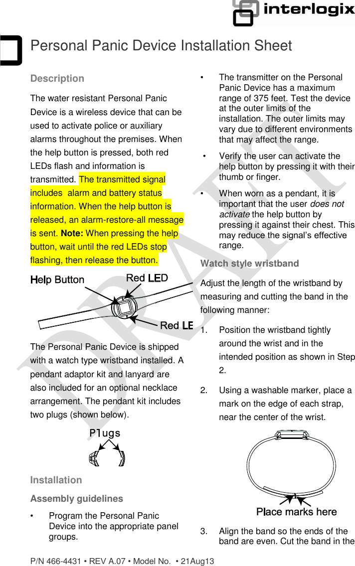
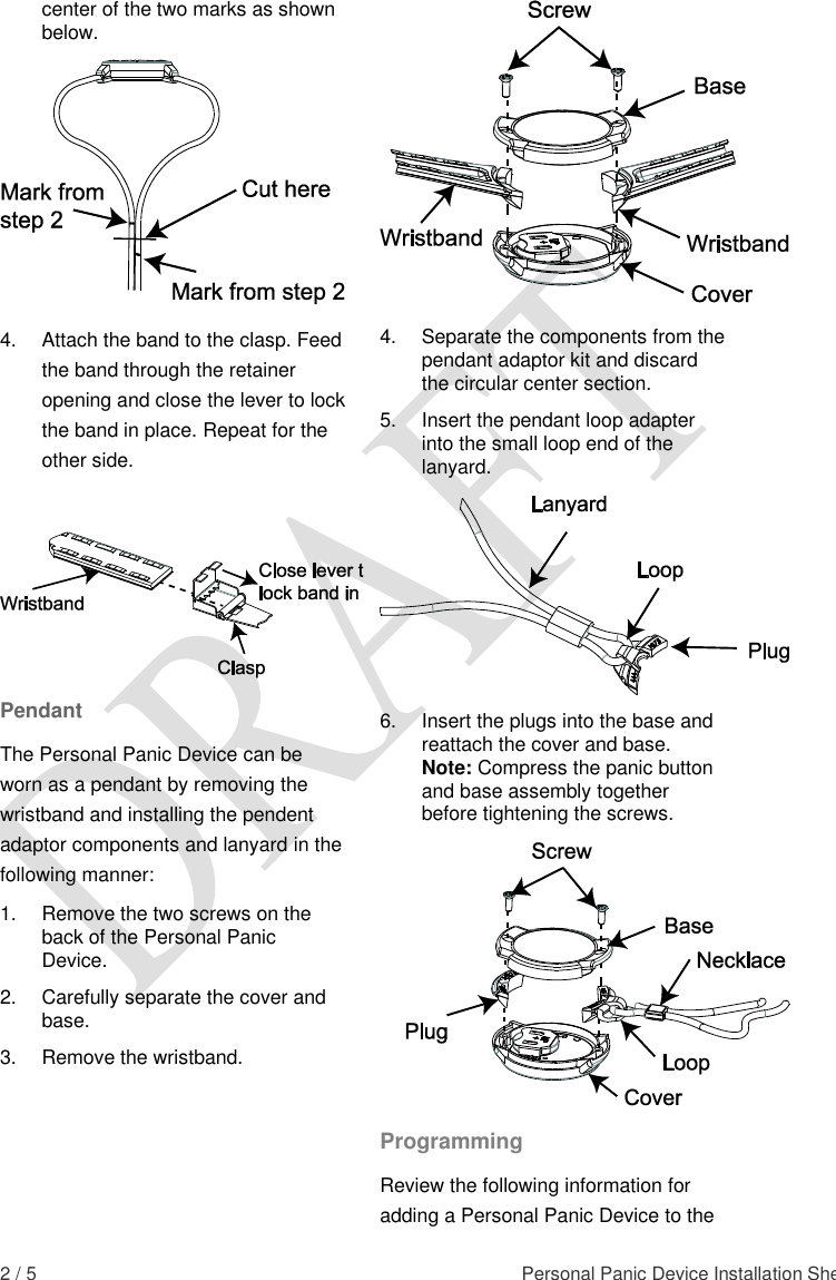
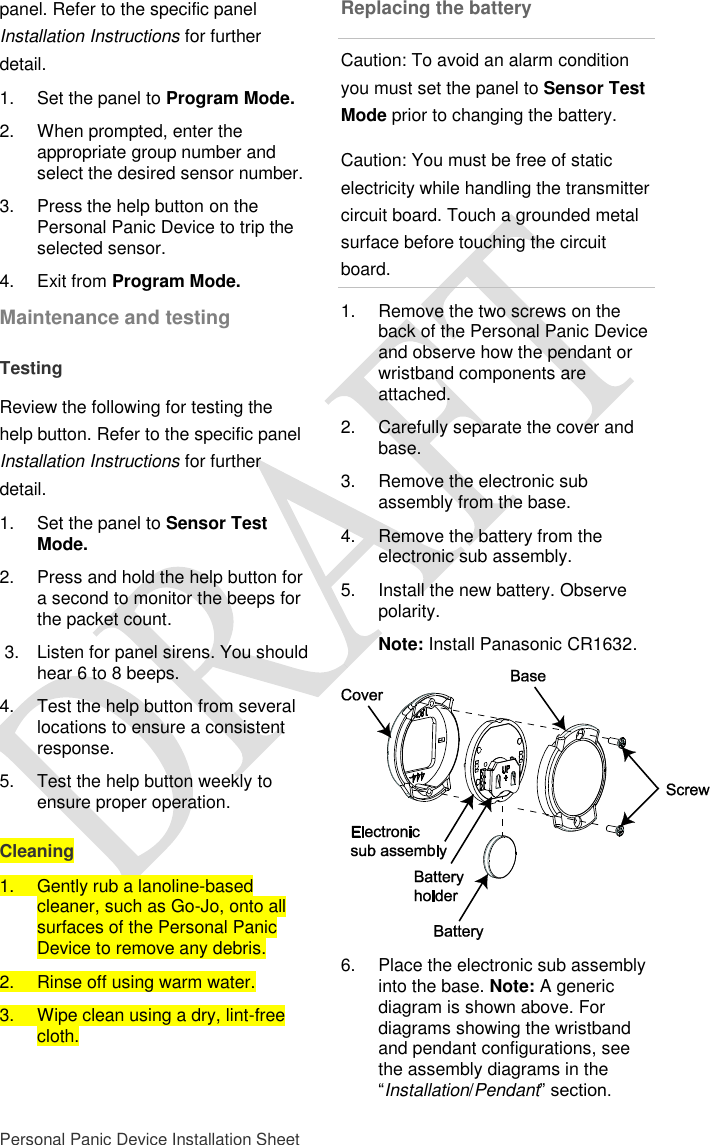
UTC Fire & Security Americas Corporation, Inc. TX-4200-01 Personal Panic Device Installation Sheet

User Manual

 P/N 466-4431 • REV A.07 • Model No.  • 21Aug13  1 / 5  Personal Panic Device Installation Sheet Description The water resistant Personal Panic Device is a wireless device that can be used to activate police or auxiliary alarms throughout the premises. When the help button is pressed, both red LEDs flash and information is transmitted. The transmitted signal includes  alarm and battery status information. When the help button is released, an alarm-restore-all message is sent. Note: When pressing the help button, wait until the red LEDs stop flashing, then release the button.  The Personal Panic Device is shipped with a watch type wristband installed. A pendant adaptor kit and lanyard are also included for an optional necklace arrangement. The pendant kit includes two plugs (shown below).  Installation Assembly guidelines •  Program the Personal Panic Device into the appropriate panel groups. •  The transmitter on the Personal Panic Device has a maximum range of 375 feet. Test the device at the outer limits of the installation. The outer limits may vary due to different environments that may affect the range.  •   Verify the user can activate the help button by pressing it with their thumb or finger. •   When worn as a pendant, it is important that the user does not activate the help button by pressing it against their chest. This may reduce the signal’s effective range. Watch style wristband Adjust the length of the wristband by measuring and cutting the band in the following manner: 1.  Position the wristband tightly around the wrist and in the intended position as shown in Step 2. 2.  Using a washable marker, place a mark on the edge of each strap, near the center of the wrist.  3.   Align the band so the ends of the band are even. Cut the band in the
 2 / 5  Personal Panic Device Installation Sheet center of the two marks as shown below.  4.  Attach the band to the clasp. Feed the band through the retainer opening and close the lever to lock the band in place. Repeat for the other side.   Pendant The Personal Panic Device can be worn as a pendant by removing the wristband and installing the pendent adaptor components and lanyard in the following manner: 1.  Remove the two screws on the back of the Personal Panic Device.  2.  Carefully separate the cover and base. 3.  Remove the wristband.  4.  Separate the components from the pendant adaptor kit and discard the circular center section. 5.  Insert the pendant loop adapter into the small loop end of the lanyard.  6.  Insert the plugs into the base and reattach the cover and base. Note: Compress the panic button and base assembly together before tightening the screws.  Programming Review the following information for adding a Personal Panic Device to the
 Personal Panic Device Installation Sheet  3 / 5 panel. Refer to the specific panel Installation Instructions for further detail. 1.  Set the panel to Program Mode. 2.  When prompted, enter the appropriate group number and select the desired sensor number. 3.  Press the help button on the Personal Panic Device to trip the selected sensor. 4.  Exit from Program Mode. Maintenance and testing Testing  Review the following for testing the help button. Refer to the specific panel Installation Instructions for further detail. 1.  Set the panel to Sensor Test Mode. 2.  Press and hold the help button for a second to monitor the beeps for the packet count.  3.  Listen for panel sirens. You should hear 6 to 8 beeps. 4.  Test the help button from several locations to ensure a consistent response. 5.  Test the help button weekly to ensure proper operation. Cleaning 1.  Gently rub a lanoline-based cleaner, such as Go-Jo, onto all surfaces of the Personal Panic Device to remove any debris. 2.  Rinse off using warm water. 3.  Wipe clean using a dry, lint-free cloth. Replacing the battery Caution: To avoid an alarm condition you must set the panel to Sensor Test Mode prior to changing the battery. Caution: You must be free of static electricity while handling the transmitter circuit board. Touch a grounded metal surface before touching the circuit board. 1.  Remove the two screws on the back of the Personal Panic Device and observe how the pendant or wristband components are attached.  2.  Carefully separate the cover and base. 3.   Remove the electronic sub assembly from the base.  4.  Remove the battery from the electronic sub assembly. 5.  Install the new battery. Observe polarity.  Note: Install Panasonic CR1632.  6.  Place the electronic sub assembly into the base. Note: A generic diagram is shown above. For diagrams showing the wristband and pendant configurations, see the assembly diagrams in the “Installation/Pendant” section.
 4 / 5  Personal Panic Device Installation Sheet 7.  Inspect the water seal area and the plugs to ensure they are free from debris.  8. Reattach the cover, lanyard assembly or wristband and the base. Note: Press the pushbutton and cover together before tightening the screws. 9.  Test the help button for proper operation. Specifications Model no. TX-4200-01-1 (white) TX-4200-01-2  (black) RF frequency 319.5 MHz Compatibility Interlogix Learn Mode Panels and Receivers Battery type 3.0 V lithium (CR1632) Recommended battery: Panasonic CR1632  Typical standby current (μA): ≤ 1 Estimated battery life (at 20° C):  4 years Supervisory interval:  Less than 64 minutes  Typical RF output power:  .25 mW Operating temperature range 32° to 120°F (0° to 49°C) Storage temperature range -30 to 140°F (-34 to 60°C) Relative humidity 5-90% non-condensing Dimensions  (L x W x D) 1.60 x 1.40 x 0.410 in. (4.1 x 3.6 x 1.0 cm)
 Personal Panic Device Installation Sheet  5 / 5 Regulatory Information This device complies with FCC Rules Part 15. Operation is subject to the following two conditions: 1.  This device may not cause harmful interference. 2.  This device must accept any interference that may be received, including interference that may cause undesired operation. Changes or modifications not expressly approved by Interlogix can void the user’s authority to operate the equipment. FCC ID:  B4Z-984-PANIC IC: 1175C-984PANIC US Patents 4,855,713; 4,864,636, and others pending. Contact information For general information, see www.utcfireandsecurity.com or www.interlogix.com. For customer support, see www.interlogix.com/customer-support or call +1 855 286 8889. Trademark/Copyright © 2013 UTC Fire & Security Americas Corporation, Inc. Interlogix is part of UTC Climate Controls & Security, a unit of United Technologies Corporation. All rights reserved.                  This device complies with part 15 of the FCC Rules. Operation is subject to the following two conditions: (1) This device may not cause harmful interference, and (2) this device must accept any interference received, including interference that may cause undesired operation.   Changes or modifications not expressly approved by Interlogix can void the user’s authority to operate the equipment.  FCC ID: B4Z-984-PANIC  IC: 1175C-984PANIC  This Class B digital apparatus complies with Canadian ICES-003. Cet appareil numérique de la classe B est conforme à la norme NMB-003 du Canada.  Le fonctionnement est soumis aux deux conditions suivantes : (1) cet appareil peut ne pas provoquer d’interférences et (2) cet appareil doit accepter toutes interférences, y compris les interférences pouvant provoquer un fonctionnement non désiré de l’appareil.

Navigation menu