UTC Fire and Security Americas CGGAA3 Motion Detector User Manual User Manaual
UTC Fire & Security Americas Corporation, Inc. Motion Detector User Manaual
UserManual.wiki
>
UTC Fire and Security Americas
>
CGGAA3 User Manual
User Manaual
Navigation menu
Upload a User Manual
Namespaces
Wiki Guide
HTML
PDF
Info
Views
User Manual
Discussion / Help
Navigation
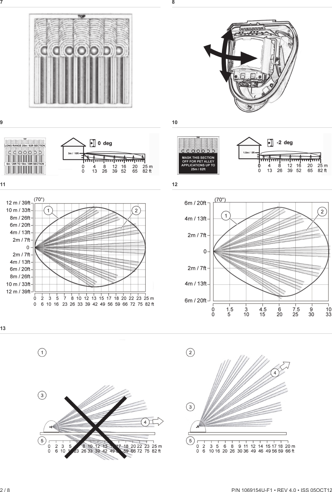
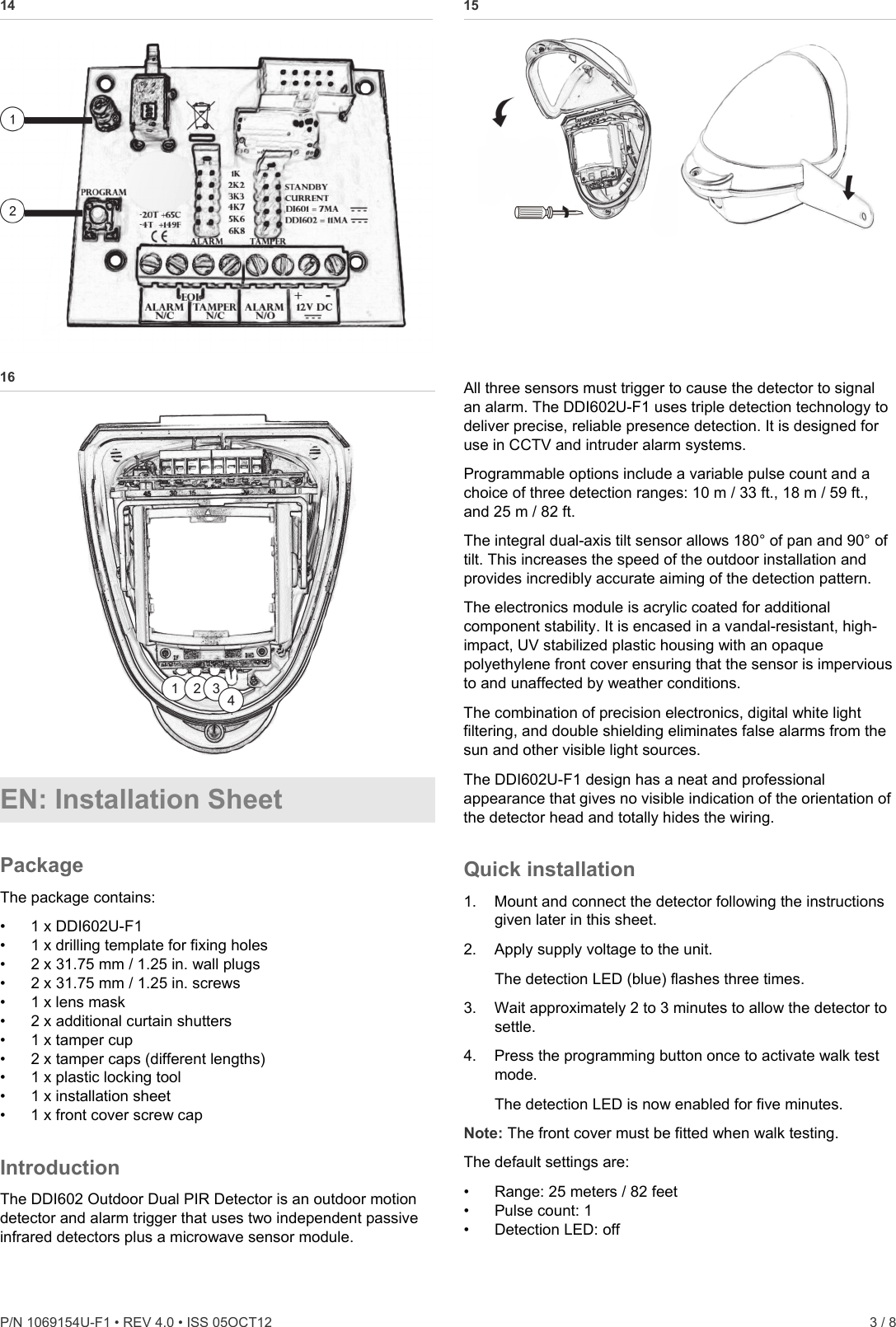
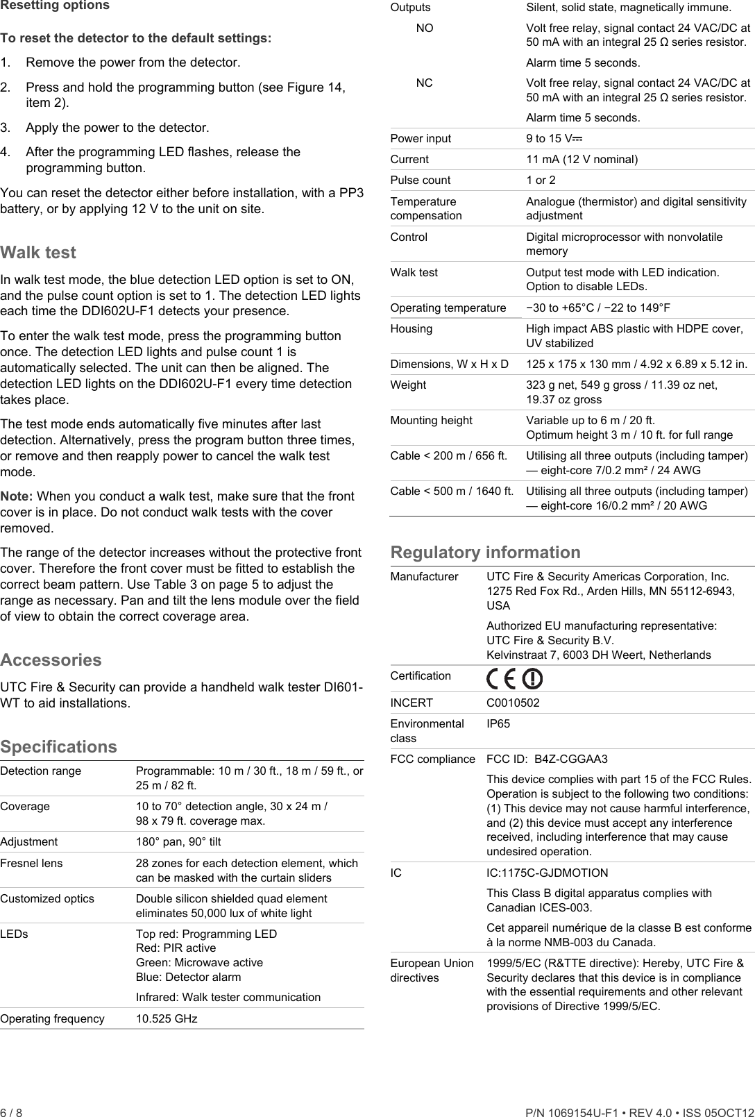
![P/N 1069154U-F1 • REV 4.0 • ISS 05OCT12 5 / 8 Table 2 below summarizes typical masking configurations for use when the range option is set to 25 meters. Table 2: Masking configurations for maximum range Configuration Height (m / ft.) Tilt (°) Max. range (m / ft.) ReferenceMultibeam, optimum 3 / 10 0 25 / 82 Figure 9 Pet immunity [1] 1.5 / 5 −2 25 / 82 Figure 10 [1] Black area should be masked for pet alley applications up to 30 meters / 98 feet. [2] Black area should be masked for curtain coverage applications. Figure 11 shows the pattern for the maximum range in the optimum position (see Figure 9). Masking the top section of the lens reduces the range to 18 m / 59 ft. Item 1 is the microwave coverage, item 2 is the PIR pattern. Figure 12 shows the pattern for the minimum range (10 m / 33 ft.) In this case masking the top section of the lens reduces the range to 6 meters. Figure 13 shows possible alignments when the detector is mounted close to a wall. Figure 13 legend Item Description 1. 90° mounting, not recommended 2. 55° mounting, recommended 3. Detector housing 4. Long range beam direction 5. Wall The alignment shown as item 1 in Figure 13 is not recommended. If the detector head is mounted at an angle of 90° to the perimeter, the mounting wall may cut off short and medium range beams. The long-range beam still will detect an intruder, however the wall can cause false alarms when heated by sunlight. Item 2 in Figure 13 shows the recommended alignment. The detector head is mounted at a 55° angle to the perimeter. As a result, short and medium range beams are parallel to the perimeter, but the detection range along the perimeter is reduced to 20 m. LEDs LEDs are shown on Figure 16. Figure 16 legend Item Colour Description 1. Red PIR active 2. Green Microwave active 3. Blue Detection alarm 4. Infrared Walk tester communication Programmable options Pulse count Pulse count is the number of times the detector must detect a presence before signalling an alarm. The DDI602U-F1 includes magnetically immune, volt-free relay contacts that can be used to trigger alarm inputs on connected equipment. The contacts are rated at a maximum of 24 V AC/DC at 50 mA. When the pulse count is set to 1, the detector is most sensitive. Detection LED enabled • Off: Detection LED is disabled • On: Detection LED signals detection Programming Figure 14 legend Item Description 1. Programming LED (red) 2. Programming button All available settings are listed in Table 3 below. Table 3: Programming settings Value Option 1 2 3 1. Range (m / ft.) 10 / 33 18 / 59 25 / 82* 2. Pulse count 1* 2 3. Detection LED OFF* ON * Default settings To change any of DDI602U-F1 settings: 1. Press the programming button to select the option number you want to change. Press once for range, twice for pulse count, and three times for detection LED. 2. Wait until the programming (red) LED turns off (typically 4 seconds). 3. Count the number of times the programming LED flashes to determine the current value for that option. 4. Press the programming button to select the value number for the new setting. Example: To set the range to 30 m / 98 ft., press three times. The programming LED blinks twice to indicate that the new value was set. Any alterations made to DDI602U-F1 settings are stored in the detector’s nonvolatile memory. Example To change the detection LED setting from OFF to ON: 1. Press the programming button three times. 2. Wait until the programming LED turns off. 3. The programming LED flashes once to show that the current value is off. 4. Press the programming button twice. 5. The programming LED flashes twice showing that the new value has been stored. The detector returns to normal operation.](https://usermanual.wiki/UTC-Fire-and-Security-Americas/CGGAA3/User-Guide-1826112-Page-5.png)