UTC Fire and Security Americas CGGAA3 Motion Detector User Manual User Manaual
UTC Fire & Security Americas Corporation, Inc. Motion Detector User Manaual
User Manaual
© 2012 UTC Fire & Security. All rights reserved. 1 / 8 P/N 1069154U-F1 • REV 4.0 • ISS 05OCT12
DDI602U-F1 Outdoor Dual PIR Detector
Installation Sheet
EN
1
2
3
4
5
6
2 / 8 P/N 1069154U-F1 • REV 4.0 • ISS 05OCT12
7
8
9 10
11 12
13
P/N 1069154U-F1 • REV 4.0 • ISS 05OCT12 3 / 8
14 15
16
EN: Installation Sheet
Package
The package contains:
• 1 x DDI602U-F1
• 1 x drilling template for fixing holes
• 2 x 31.75 mm / 1.25 in. wall plugs
• 2 x 31.75 mm / 1.25 in. screws
• 1 x lens mask
• 2 x additional curtain shutters
• 1 x tamper cup
• 2 x tamper caps (different lengths)
• 1 x plastic locking tool
• 1 x installation sheet
• 1 x front cover screw cap
Introduction
The DDI602 Outdoor Dual PIR Detector is an outdoor motion
detector and alarm trigger that uses two independent passive
infrared detectors plus a microwave sensor module.
All three sensors must trigger to cause the detector to signal
an alarm. The DDI602U-F1 uses triple detection technology to
deliver precise, reliable presence detection. It is designed for
use in CCTV and intruder alarm systems.
Programmable options include a variable pulse count and a
choice of three detection ranges: 10 m / 33 ft., 18 m / 59 ft.,
and 25 m / 82 ft.
The integral dual-axis tilt sensor allows 180° of pan and 90° of
tilt. This increases the speed of the outdoor installation and
provides incredibly accurate aiming of the detection pattern.
The electronics module is acrylic coated for additional
component stability. It is encased in a vandal-resistant, high-
impact, UV stabilized plastic housing with an opaque
polyethylene front cover ensuring that the sensor is impervious
to and unaffected by weather conditions.
The combination of precision electronics, digital white light
filtering, and double shielding eliminates false alarms from the
sun and other visible light sources.
The DDI602U-F1 design has a neat and professional
appearance that gives no visible indication of the orientation of
the detector head and totally hides the wiring.
Quick installation
1. Mount and connect the detector following the instructions
given later in this sheet.
2. Apply supply voltage to the unit.
The detection LED (blue) flashes three times.
3. Wait approximately 2 to 3 minutes to allow the detector to
settle.
4. Press the programming button once to activate walk test
mode.
The detection LED is now enabled for five minutes.
Note: The front cover must be fitted when walk testing.
The default settings are:
• Range: 25 meters / 82 feet
• Pulse count: 1
• Detection LED: off

4 / 8 P/N 1069154U-F1 • REV 4.0 • ISS 05OCT12
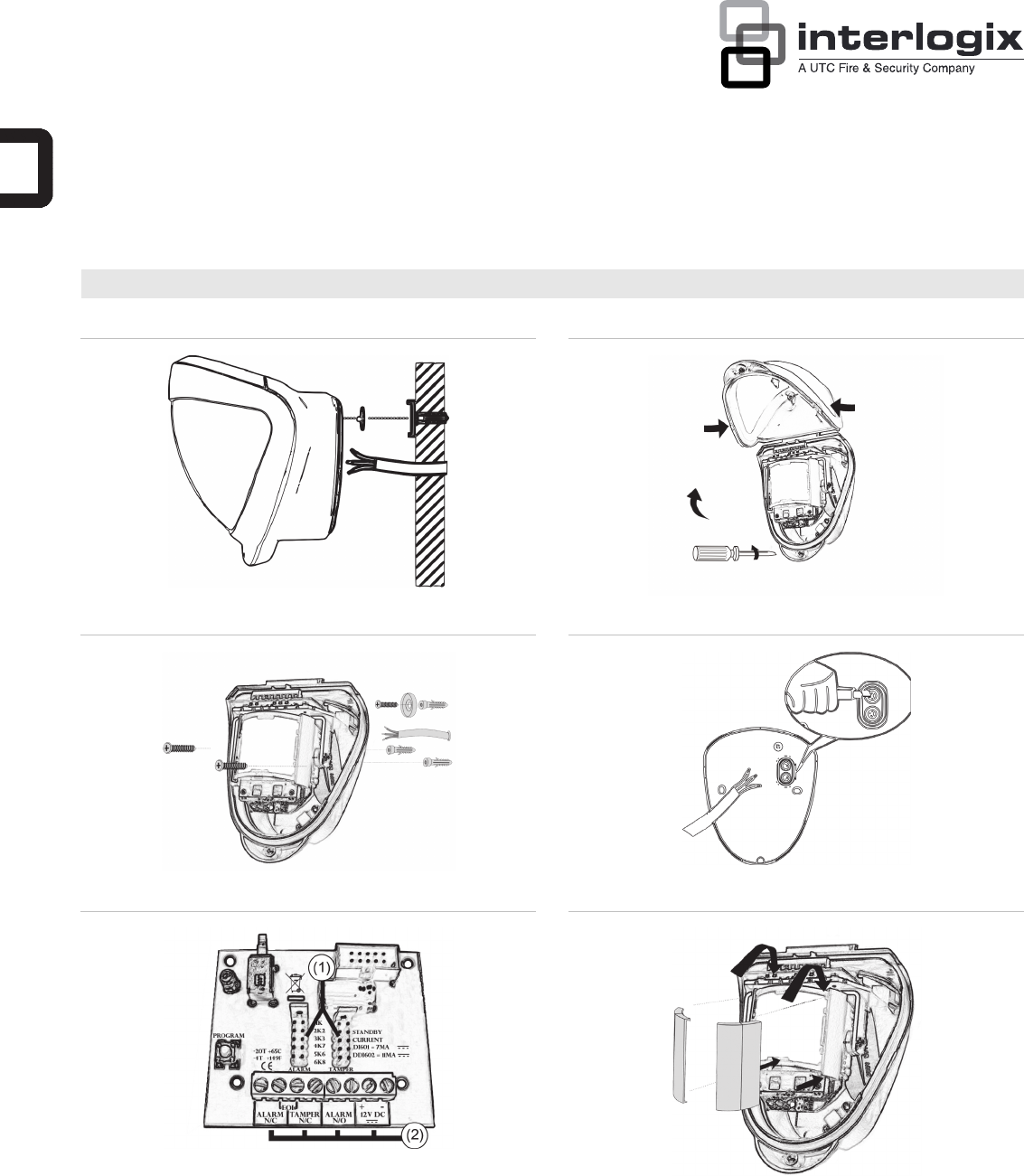
Mounting the unit
During installation, protect the electronics against water, as
trapped moisture can affect or damage the unit.
To mount the detector:
1. Drill the wall to accept the two fixing screws, the cable
entry, and the tamper cup (if used). See Figures 1 and 3.
A hole-drilling template is provided.
Notes
• Leave a minimum 10 cm (4 inches) clearance above
the top of the detector housing to allow the cover and
the detector to be positioned correctly.
• We recommend using the tamper cup on uneven wall
surfaces.
• When mounting the units side by side, a minimum
space of 1 m must be left between the detectors and
the detectors must not be looking directly towards
each other. No minimum space is required when
mounting the units back to back.
• The recommended optimum mounting height for the
detector is 3 m. Whilst it is possible to mount the unit
higher, this will give a reduced detection range and
will require the detection subject to move further
through the already reduced detection area before an
activation is signalled.
2. Remove the cover assembly by loosening the locking
screw. Squeeze the sides of the front cover to release the
internal catches. The cover hinges from the top and lifts
out of the location slot. See Figure 2.
3. Use a razor knife to open a rubber seal to allow the
cabling into the unit (see Figure 4). Feed standard eight-
core alarm cable into the cable entry. Bare the wires and
connect to the top PCB terminal block (Figure 5, item 2).
4. Screw the unit to the wall ensuring that the tamper pin is
correctly located and that the tamper microswitch is
closed.
To aid installation, two spare tamper feet are provided.
One is 1 mm shorter and the other is 1 mm longer than the
tamper foot originally fitted. The tamper foot is a push fit
and can be removed by carefully pulling it from the pin.
See Figure 1.
5. When the detector is aligned, connected, and
programmed to suit the installation:
a. Fit the cover to the detector base.
b. Lightly screw the locking screw.
c. Put the top of the locking tool into the small notch on
each side of the cover, and then apply slight pressure
until the cover locks into the base, as shown in
Figure 15.
d. Tighten the locking screw.
Connecting the unit
The DDI602U-F1 includes jumpers that let you configure
internal end-of-line (EOL) resistor values, when EOL resistors
are required. Values are: 1, 2.2, 3.3, 4.7, 5.6, and 6.8 kΩ.
Figure 5 shows:
1. EOL resistor jumpers
2. Wiring points
Alternatively, you can remove the jumpers and connect a
discrete resistor directly to the alarm or tamper outputs, as
specified by third-party equipment.
Table 1: Connections
Terminal Label Description
1, 2 ALARM N/C Alarm relay, normally closed
2, 3 EOL End-of-line resistors
3, 4 TAMPER
N/C
Tamper relay, normally closed
5, 6 ALARM N/O Alarm relay, normally open
7, 8 +, − 12V DC 12 V power supply
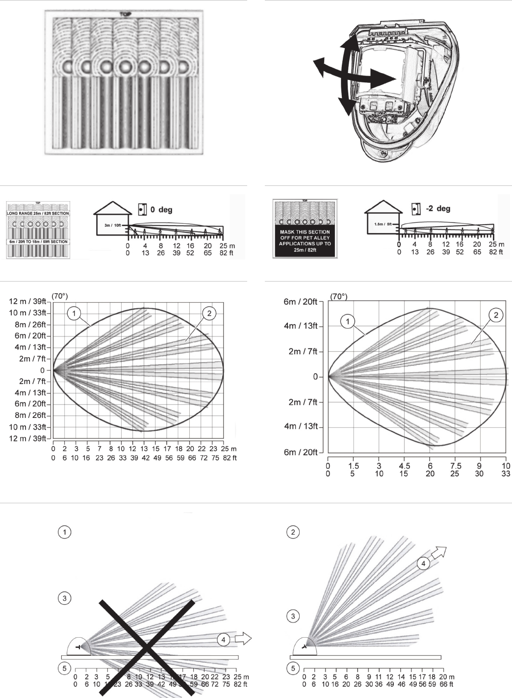
Multibeam alignment and masking
The multifunction lens fitted to the DDI602U-F1 detector
produces seven long-range beams and seven medium- to
short-range curtain PIR beams. The PIR circuitry detects
changes in heat and movement in the beam pattern; therefore
items such as trees, shrubs, ponds, boiler flues, and animals
should be considered when positioning the detector. The
microwave module detects actual movement towards or away
from the detector and is programmed to ignore any objects that
move outside of the preselected detection range.
Note: PIR sensor is more sensitive to a movement across the
beams, and less sensitive to a movement directly towards or
away from the beams. Microwave sensor is more sensitive to
movement towards and away from the sensor.
The detector module is fitted with two sliding shutters to reduce
the detection angle of the PIR sensor only.
The curtains are fitted to the pan and tilt module as shown in
Figure 6. Each section of the detector lens gives a coverage
pattern of approximately 10 degrees.
An additional set of curtain sliders is provided should the beam
pattern be narrowed even further, e.g. if the minimum detection
angle of 10 degrees is required.
When coverage exceeds the desired detection area, adjust the
module as required and mask off any beams, either vertically
or horizontally, to avoid unwanted detection.
Use portions of the self-adhesive silver mask applied to the
rear, smooth side of the lens as shown in Figures 9 and 10.
Gently lift the top and bottom edges of the pan and tilt module
to release the lens. To replace the module, please begin by
sliding one side of the lens into the clips on the pan and tilt
module. After one side is secure, do the same for the opposite
side. Once both sides are secure, gently lift the top and bottom
edges of the pan and tilt module and press on the lens to click
it into place.
Always replace the lens the correct way up to ensure exact
beam pattern coverage. The top of the lens is marked TOP as
shown in Figure 7.

P/N 1069154U-F1 • REV 4.0 • ISS 05OCT12 5 / 8
Table 2 below summarizes typical masking configurations for
use when the range option is set to 25 meters.
Table 2: Masking configurations for maximum range
Configuration Height
(m / ft.)
Tilt (°) Max. range
(m / ft.)
Reference
Multibeam, optimum 3 / 10 0 25 / 82 Figure 9
Pet immunity [1] 1.5 / 5 −2 25 / 82 Figure 10
[1] Black area should be masked for pet alley applications up to
30 meters / 98 feet.
[2] Black area should be masked for curtain coverage applications.
Figure 11 shows the pattern for the maximum range in the
optimum position (see Figure 9). Masking the top section of the
lens reduces the range to 18 m / 59 ft. Item 1 is the microwave
coverage, item 2 is the PIR pattern.
Figure 12 shows the pattern for the minimum range (10 m /
33 ft.) In this case masking the top section of the lens reduces
the range to 6 meters.
Figure 13 shows possible alignments when the detector is
mounted close to a wall.
Figure 13 legend
Item Description
1. 90° mounting, not recommended
2. 55° mounting, recommended
3. Detector housing
4. Long range beam direction
5. Wall
The alignment shown as item 1 in Figure 13 is not
recommended. If the detector head is mounted at an angle of
90° to the perimeter, the mounting wall may cut off short and
medium range beams. The long-range beam still will detect an
intruder, however the wall can cause false alarms when heated
by sunlight.
Item 2 in Figure 13 shows the recommended alignment. The
detector head is mounted at a 55° angle to the perimeter. As a
result, short and medium range beams are parallel to the
perimeter, but the detection range along the perimeter is
reduced to 20 m.
LEDs
LEDs are shown on Figure 16.
Figure 16 legend
Item Colour Description
1. Red PIR active
2. Green Microwave active
3. Blue Detection alarm
4. Infrared Walk tester communication
Programmable options
Pulse count
Pulse count is the number of times the detector must detect a
presence before signalling an alarm.
The DDI602U-F1 includes magnetically immune, volt-free relay
contacts that can be used to trigger alarm inputs on connected
equipment.
The contacts are rated at a maximum of 24 V AC/DC at 50 mA.
When the pulse count is set to 1, the detector is most sensitive.
Detection LED enabled
• Off: Detection LED is disabled
• On: Detection LED signals detection
Programming
Figure 14 legend
Item Description
1. Programming LED (red)
2. Programming button
All available settings are listed in Table 3 below.
Table 3: Programming settings
Value
Option 1 2 3
1. Range (m / ft.) 10 / 33 18 / 59 25 / 82*
2. Pulse count 1* 2
3. Detection LED OFF* ON
* Default settings
To change any of DDI602U-F1 settings:
1. Press the programming button to select the option number
you want to change. Press once for range, twice for pulse
count, and three times for detection LED.
2. Wait until the programming (red) LED turns off (typically
4 seconds).
3. Count the number of times the programming LED flashes
to determine the current value for that option.
4. Press the programming button to select the value number
for the new setting. Example: To set the range to 30 m /
98 ft., press three times.
The programming LED blinks twice to indicate that the
new value was set.
Any alterations made to DDI602U-F1 settings are stored in the
detector’s nonvolatile memory.
Example
To change the detection LED setting from OFF to ON:
1. Press the programming button three times.
2. Wait until the programming LED turns off.
3. The programming LED flashes once to show that the
current value is off.
4. Press the programming button twice.
5. The programming LED flashes twice showing that the new
value has been stored. The detector returns to normal
operation.

6 / 8 P/N 1069154U-F1 • REV 4.0 • ISS 05OCT12
Resetting options
To reset the detector to the default settings:
1. Remove the power from the detector.
2. Press and hold the programming button (see Figure 14,
item 2).
3. Apply the power to the detector.
4. After the programming LED flashes, release the
programming button.
You can reset the detector either before installation, with a PP3
battery, or by applying 12 V to the unit on site.
Walk test
In walk test mode, the blue detection LED option is set to ON,
and the pulse count option is set to 1. The detection LED lights
each time the DDI602U-F1 detects your presence.
To enter the walk test mode, press the programming button
once. The detection LED lights and pulse count 1 is
automatically selected. The unit can then be aligned. The
detection LED lights on the DDI602U-F1 every time detection
takes place.
The test mode ends automatically five minutes after last
detection. Alternatively, press the program button three times,
or remove and then reapply power to cancel the walk test
mode.
Note: When you conduct a walk test, make sure that the front
cover is in place. Do not conduct walk tests with the cover
removed.
The range of the detector increases without the protective front
cover. Therefore the front cover must be fitted to establish the
correct beam pattern. Use Table 3 on page 5 to adjust the
range as necessary. Pan and tilt the lens module over the field
of view to obtain the correct coverage area.
Accessories
UTC Fire & Security can provide a handheld walk tester DI601-
WT to aid installations.
Specifications
Detection range Programmable: 10 m / 30 ft., 18 m / 59 ft., or
25 m / 82 ft.
Coverage 10 to 70° detection angle, 30 x 24 m /
98 x 79 ft. coverage max.
A
djustment 180° pan, 90° tilt
Fresnel lens 28 zones for each detection element, which
can be masked with the curtain sliders
Customized optics Double silicon shielded quad element
eliminates 50,000 lux of white light
LEDs Top red: Programming LED
Red: PIR active
Green: Microwave active
Blue: Detector alarm
Infrared: Walk tester communication
Operating frequency 10.525 GHz
Outputs Silent, solid state, magnetically immune.
NO Volt free relay, signal contact 24 VAC/DC at
50 mA with an integral 25 Ω series resistor.
Alarm time 5 seconds.
NC Volt free relay, signal contact 24 VAC/DC at
50 mA with an integral 25 Ω series resistor.
Alarm time 5 seconds.
Power input 9 to 15 V
Current 11 mA (12 V nominal)
Pulse count 1 or 2
Temperature
compensation
Analogue (thermistor) and digital sensitivity
adjustment
Control Digital microprocessor with nonvolatile
memory
Walk test Output test mode with LED indication.
Option to disable LEDs.
Operating temperature −30 to +65°C / −22 to 149°F
Housing High impact ABS plastic with HDPE cover,
UV stabilized
Dimensions, W x H x D 125 x 175 x 130 mm / 4.92 x 6.89 x 5.12 in.
Weight 323 g net, 549 g gross / 11.39 oz net,
19.37 oz gross
Mounting height Variable up to 6 m / 20 ft.
Optimum height 3 m / 10 ft. for full range
Cable < 200 m / 656 ft. Utilising all three outputs (including tamper)
— eight-core 7/0.2 mm² / 24 AWG
Cable < 500 m / 1640 ft. Utilising all three outputs (including tamper)
— eight-core 16/0.2 mm² / 20 AWG
Regulatory information
Manufacturer UTC Fire & Security Americas Corporation, Inc.
1275 Red Fox Rd., Arden Hills, MN 55112-6943,
USA
Authorized EU manufacturing representative:
UTC Fire & Security B.V.
Kelvinstraat 7, 6003 DH Weert, Netherlands
Certification
INCERT C0010502
Environmental
class
IP65
FCC compliance FCC ID: B4Z-CGGAA3
This device complies with part 15 of the FCC Rules.
Operation is subject to the following two conditions:
(1) This device may not cause harmful interference,
and (2) this device must accept any interference
received, including interference that may cause
undesired operation.
IC IC:1175C-GJDMOTION
This Class B digital apparatus complies with
Canadian ICES-003.
Cet appareil numérique de la classe B est conforme
à la norme NMB-003 du Canada.
European Union
directives
1999/5/EC (R&TTE directive): Hereby, UTC Fire &
Security declares that this device is in compliance
with the essential requirements and other relevant
provisions of Directive 1999/5/EC.

P/N 1069154U-F1 • REV 4.0 • ISS 05OCT12 7 / 8
2002/96/EC (WEEE directive): Products marked
with this symbol cannot be disposed of as unsorted
municipal waste in the European Union. For proper
recycling, return this product to your local supplier
upon the purchase of equivalent new equipment, or
dispose of it at designated collection points. For
more information see: www.recyclethis.info.
Usage
restrictions
Only use the listed models in the following
countries:
DDI602U-F1
(10.525 GHz):
USA
Contact information
www.utcfireandsecurity.com or www.interlogix.com.
For customer support, see www.interlogix.com/customer-
support.
8 / 8 P/N 1069154U-F1 • REV 4.0 • ISS 05OCT12