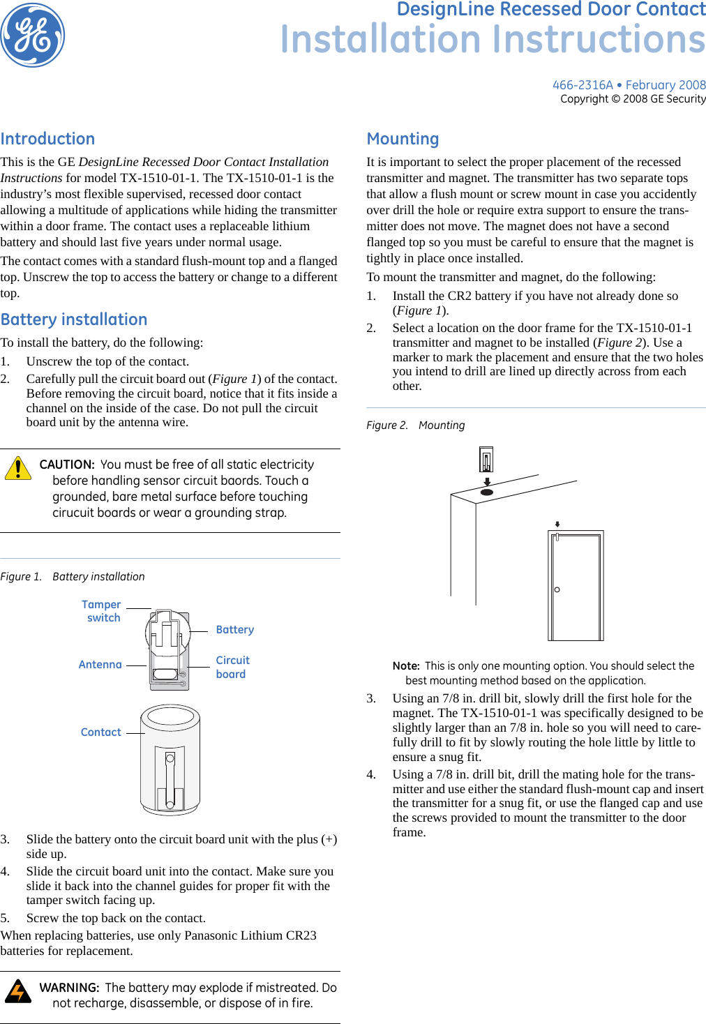
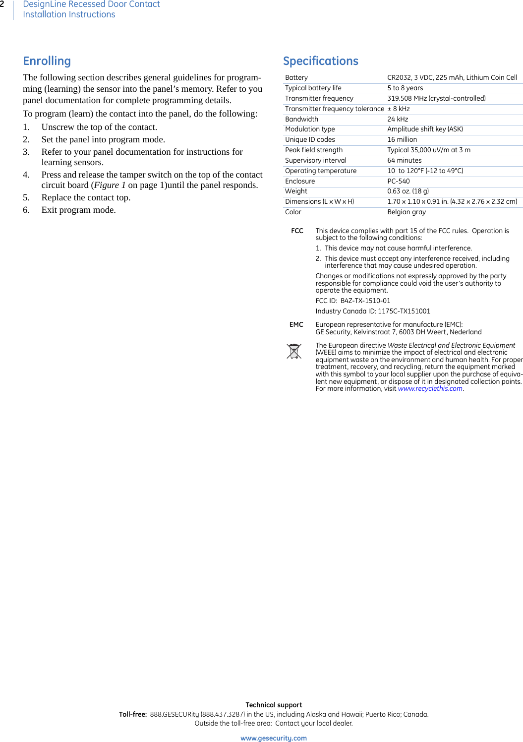
UTC Fire and Security Americas TX-1510-01 GE Recessed Door / Window Sensor User Manual 466 2316A dl tx recessed door contact inin

UTC Fire & Security Americas Corporation, Inc. GE Recessed Door / Window Sensor 466 2316A dl tx recessed door contact inin

User manual

466-2316A • February 2008Copyright © 2008 GE SecuritygDesignLine Recessed Door ContactInstallation InstructionsIntroductionThis is the GE DesignLine Recessed Door Contact Installation Instructions for model TX-1510-01-1. The TX-1510-01-1 is the industry’s most flexible supervised, recessed door contact allowing a multitude of applications while hiding the transmitter within a door frame. The contact uses a replaceable lithium battery and should last five years under normal usage.The contact comes with a standard flush-mount top and a flanged top. Unscrew the top to access the battery or change to a different top.Battery installationTo install the battery, do the following:1. Unscrew the top of the contact.2. Carefully pull the circuit board out (Figure 1) of the contact. Before removing the circuit board, notice that it fits inside a channel on the inside of the case. Do not pull the circuit board unit by the antenna wire.Figure 1. Battery installation3. Slide the battery onto the circuit board unit with the plus (+) side up.4. Slide the circuit board unit into the contact. Make sure you slide it back into the channel guides for proper fit with the tamper switch facing up.5. Screw the top back on the contact.When replacing batteries, use only Panasonic Lithium CR23 batteries for replacement. MountingIt is important to select the proper placement of the recessed transmitter and magnet. The transmitter has two separate tops that allow a flush mount or screw mount in case you accidently over drill the hole or require extra support to ensure the trans-mitter does not move. The magnet does not have a second flanged top so you must be careful to ensure that the magnet is tightly in place once installed.To mount the transmitter and magnet, do the following:1. Install the CR2 battery if you have not already done so (Figure 1).2. Select a location on the door frame for the TX-1510-01-1 transmitter and magnet to be installed (Figure 2). Use a marker to mark the placement and ensure that the two holes you intend to drill are lined up directly across from each other.Figure 2. Mounting Note:  This is only one mounting option. You should select the best mounting method based on the application.3. Using an 7/8 in. drill bit, slowly drill the first hole for the magnet. The TX-1510-01-1 was specifically designed to be slightly larger than an 7/8 in. hole so you will need to care-fully drill to fit by slowly routing the hole little by little to ensure a snug fit.4. Using a 7/8 in. drill bit, drill the mating hole for the trans-mitter and use either the standard flush-mount cap and insert the transmitter for a snug fit, or use the flanged cap and use the screws provided to mount the transmitter to the door frame.CAUTION:  You must be free of all static electricity before handling sensor circuit baords. Touch a grounded, bare metal surface before touching cirucuit boards or wear a grounding strap.WARNING:  The battery may explode if mistreated. Do not recharge, disassemble, or dispose of in fire.BatteryAntenna CircuitboardContactTamper  switch
DesignLine Recessed Door ContactInstallation Instructions2EnrollingThe following section describes general guidelines for program-ming (learning) the sensor into the panel’s memory. Refer to you panel documentation for complete programming details.To program (learn) the contact into the panel, do the following:1. Unscrew the top of the contact.2. Set the panel into program mode.3. Refer to your panel documentation for instructions for learning sensors.4. Press and release the tamper switch on the top of the contact circuit board (Figure 1 on page 1)until the panel responds.5. Replace the contact top.6. Exit program mode.SpecificationsBattery CR2032, 3 VDC, 225 mAh, Lithium Coin CellTypical battery life 5 to 8 yearsTransmitter frequency 319.508 MHz (crystal-controlled)Transmitter frequency tolerance ± 8 kHzBandwidth 24 kHzModulation type Amplitude shift key (ASK)Unique ID codes 16 millionPeak field strength Typical 35,000 uV/m at 3 mSupervisory interval 64 minutesOperating temperature 10  to 120°F (-12 to 49°C)Enclosure PC-540Weight 0.63 oz. (18 g)Dimensions (L x W x H) 1.70 x 1.10 x 0.91 in. (4.32 x 2.76 x 2.32 cm)Color Belgian grayFCC This device complies with part 15 of the FCC rules.  Operation is subject to the following conditions: 1. This device may not cause harmful interference. 2. This device must accept any interference received, including interference that may cause undesired operation. Changes or modifications not expressly approved by the party responsible for compliance could void the user’s authority to operate the equipment. FCC ID:  B4Z-TX-1510-01Industry Canada ID: 1175C-TX151001 EMC European representative for manufacture (EMC): GE Security, Kelvinstraat 7, 6003 DH Weert, NederlandThe European directive Waste Electrical and Electronic Equipment (WEEE) aims to minimize the impact of electrical and electronic equipment waste on the environment and human health. For proper treatment, recovery, and recycling, return the equipment marked with this symbol to your local supplier upon the purchase of equiva-lent new equipment, or dispose of it in designated collection points. For more information, visit www.recyclethis.com. Technical supportToll-free:  888.GESECURity (888.437.3287) in the US, including Alaska and Hawaii; Puerto Rico; Canada. Outside the toll-free area:  Contact your local dealer. www.gesecurity.com

Navigation menu