UTC Fire and Security DD669-U DD69-U User Manual DD669 U Dual Detector Installation Sheet
UTC Fire & Security B.V. DD69-U DD669 U Dual Detector Installation Sheet
UserManual.wiki
>
UTC Fire and Security
>
DD669 U User Manual
Installation info
Navigation menu
Upload a User Manual
Namespaces
Wiki Guide
HTML
PDF
Info
Views
User Manual
Discussion / Help
Navigation
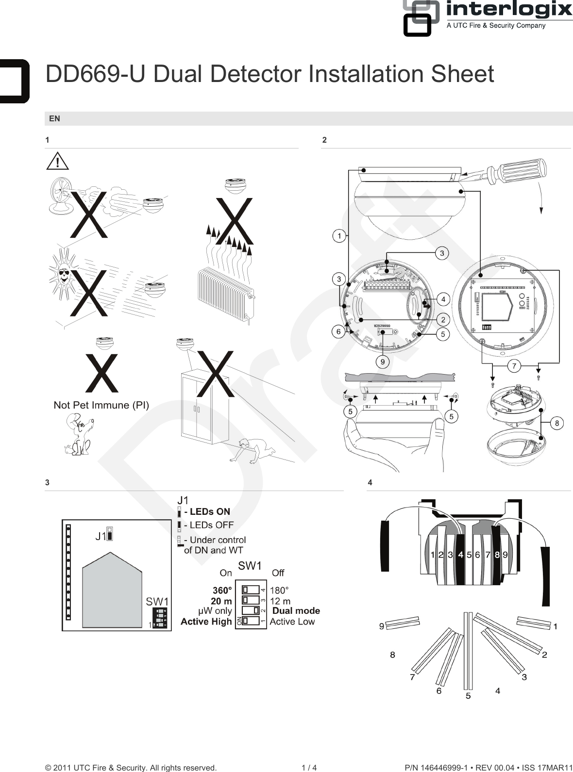
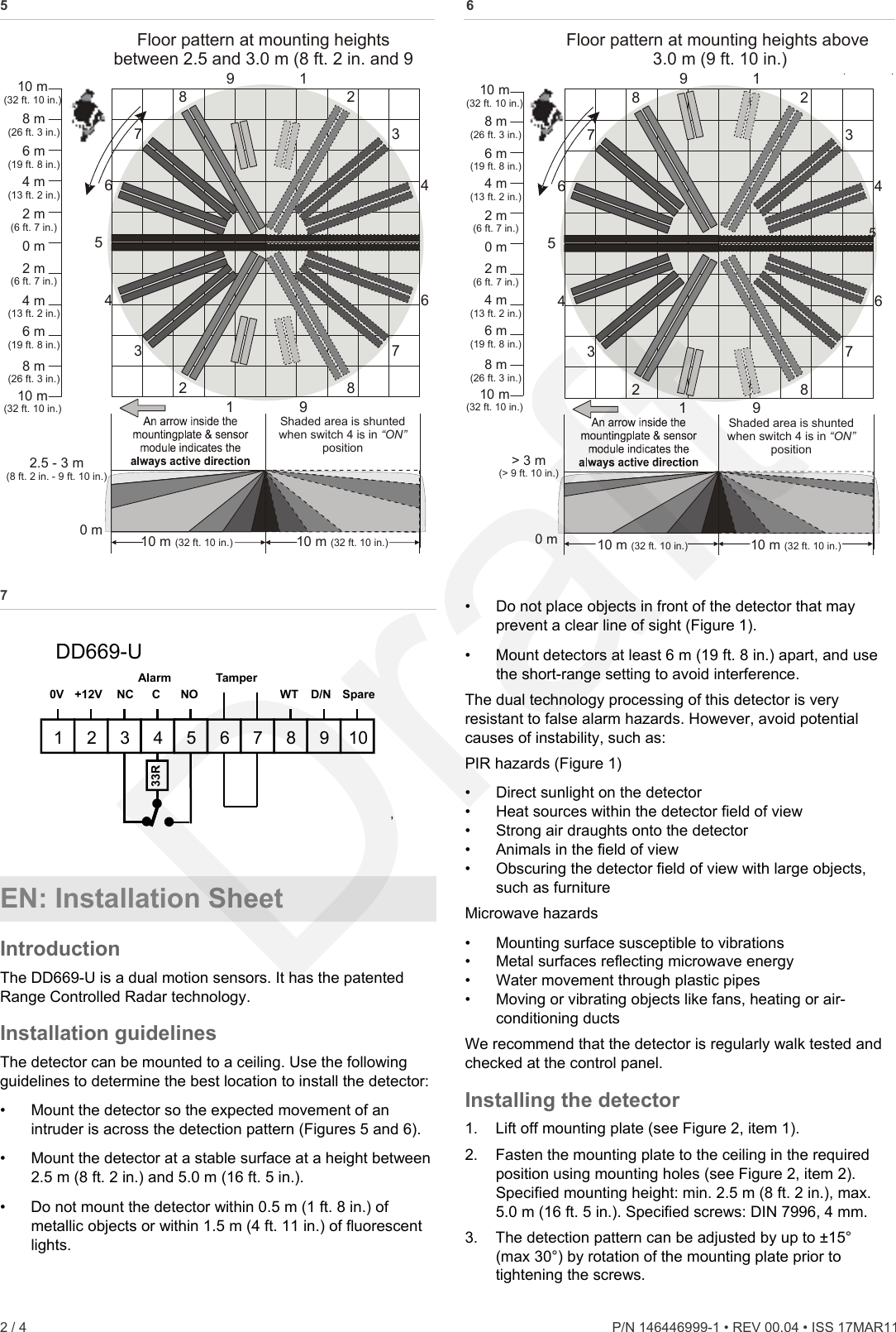
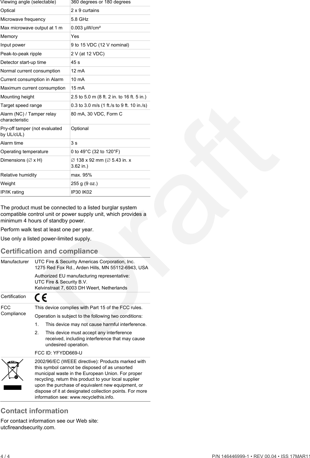
![4. Wire the detector (see Figures 2 and 7). UL/cUL installations: All wiring must be made according to National Electrical Code, NFPA70, and CSA C22.1, Canadian Electrical Code Part I, Safety Standards for electrical Installations. Increase of mounting heights beyond the specified 2.5 to 5.0 m (8 ft. 2 in. to 16 ft. 5 in.) will reduce sensitivity. Range varies from 12 to 14 meter (39 ft. 4 in. to 45 ft. 11 in.) in short range and 20 to 22 meter (65 ft. 7 in. to 72 ft. 2 in.) in long range depending on the mounting height. Note: The arrow (Figure 2, item 4) indicates the centre curtain direction and the active direction when switch 4 is OFF. 5. Select the desired jumper and DIP switch settings (see Figure 3). See section “Setting the detector” below for more information. 6. To screw the sensor module to the mounting plate, use the screws that are placed for transport in the mounting plate (see Figure 2, item 5). The curtain directions 1 through 9 clockwise, are indicated on the mounting plate (see Figure 2, item 6). Curtain number 5 is the centre curtain. Selecting the coverage patterns For access to the mirror undo screws (Figure 2, item 7) and open the sensor module (Figure 2, item 8). Mask the appropriate mirror curtains with the adhesive labels provided and reassemble the sensor module (see Figure 8 for example). Setting the detector See Figure 3 for the jumper locations in the detector. J1: Setting LEDs On: Enables both LEDs on the detector at all times (factory default). Off: Disables both LEDs on the detector at all times. Removed: Puts both LEDs under the control of the Walk Test and Day/Night input. This activates the memory feature of the detector. When the detector is Disarmed and the input Walk Test is disabled, the microwave section is turned off for DD669-U. In this configuration the detector operates as a PIR only. SW 1: Polarity setting of the control voltage (CV) On: Active High. Provides the standard UTC Fire & Security logic with “Active High” logic to enable Walk Test (WT), Day/Night (D/N), and Remote Test inputs (factory default). Off: Active Low. Provides “Active Low” logic to enable Walk Test (WT), Day/Night (D/N) and Remote Test inputs. SW 2: µW only / Dual mode On: µW only mode. Consequently the PIR circuitry is switched off and the detector will only signal alarms caused by the microwave circuitry. Off: Dual mode. In dual mode the detector signals an alarm when both technologies (microwave and PIR) have identified a target moving in the protected area (factory default). SW 3: Detector range The microwave can be selected between 20 ± 0.5 m, and 12 ± 0.5 m (65 ft. 7 in. ± 1 ft. 8 in., and 39 ft. 4 in. ± 1 ft. 8 in.) Note: Only the microwave range will be reduced, not the PIR section. SW 4: Detection coverage The detection coverage can be selected between 360 degrees for normal application, and 180 degrees for special applications. Note: Only the coverage of the PIR will be adjusted. Walk testing the detector The DD669-U provides a walk test mode for testing the detectors operation and coverage pattern if the detector is set to LED’s disabled. To walk test the detector, remove the supply voltage and apply it back on. The walk test mode can be started once the startup sequence has completely finished (LED flashes for 45 seconds). The unit stays in walk test mode for 30 minutes. The detector returns to normal operating mode after the walk test mode times out. Green mode The detector can be programmed in several ways to minimize the exposure of microwave radiation to human and animal, although the detector is already sending microwave signal on a very low power level. The detector will switch the microwave section off for 3 minutes after a dual alarm. The detector is in PIR only during this timer. Settings option 1 J1: Off SW 2: Off Settings option 2 J1: Removed SW 2: Off System in Armed status The microwave section is switched off and the detector operates in PIR mode only. Setting J1: Removed SW 2: Off System in Disarmed status System Walk Test Disabled LED indication Red [1] Green [1] Yellow [1] Alarm relay To reset Start up Closed Automatically after 45 s Low voltage Open (Alarm) Apply correct voltage PIR intruder alarm Automatically after 3 s Microwave intruder alarm Automatically after 3 s (Dual) motion intruder alarm Open (Alarm) Automatically after 3 s Latched PIR (Memory) Switch to Night mode Continuously on Normal blinking (1 Hz) [1] Tri-colour LED. Specifications Detector Dual Range diameter (selectable) 20 ±0.5 m (65 ft. 7 in. ± 1 ft. 7 in.) or 12 ±0.5 m (39 ft. 4 in. ± 1 ft. 7 in.) P/N 146446999-1 • REV 00.04 • ISS 17MAR11 3 / 4](https://usermanual.wiki/UTC-Fire-and-Security/DD669-U/User-Guide-1489676-Page-3.png)