UTC Fire and Security DD669-U DD69-U User Manual DD669 U Dual Detector Installation Sheet
UTC Fire & Security B.V. DD69-U DD669 U Dual Detector Installation Sheet
Installation info
DD669-U Dual Detector Installation Sheet
EN
1
2
3
4
© 2011 UTC Fire & Security. All rights reserved. 1 / 4 P/N 146446999-1 • REV 00.04 • ISS 17MAR11
5
1
1
2
3
4
5
6
7
8
9
9
8
7
6
4
3
2
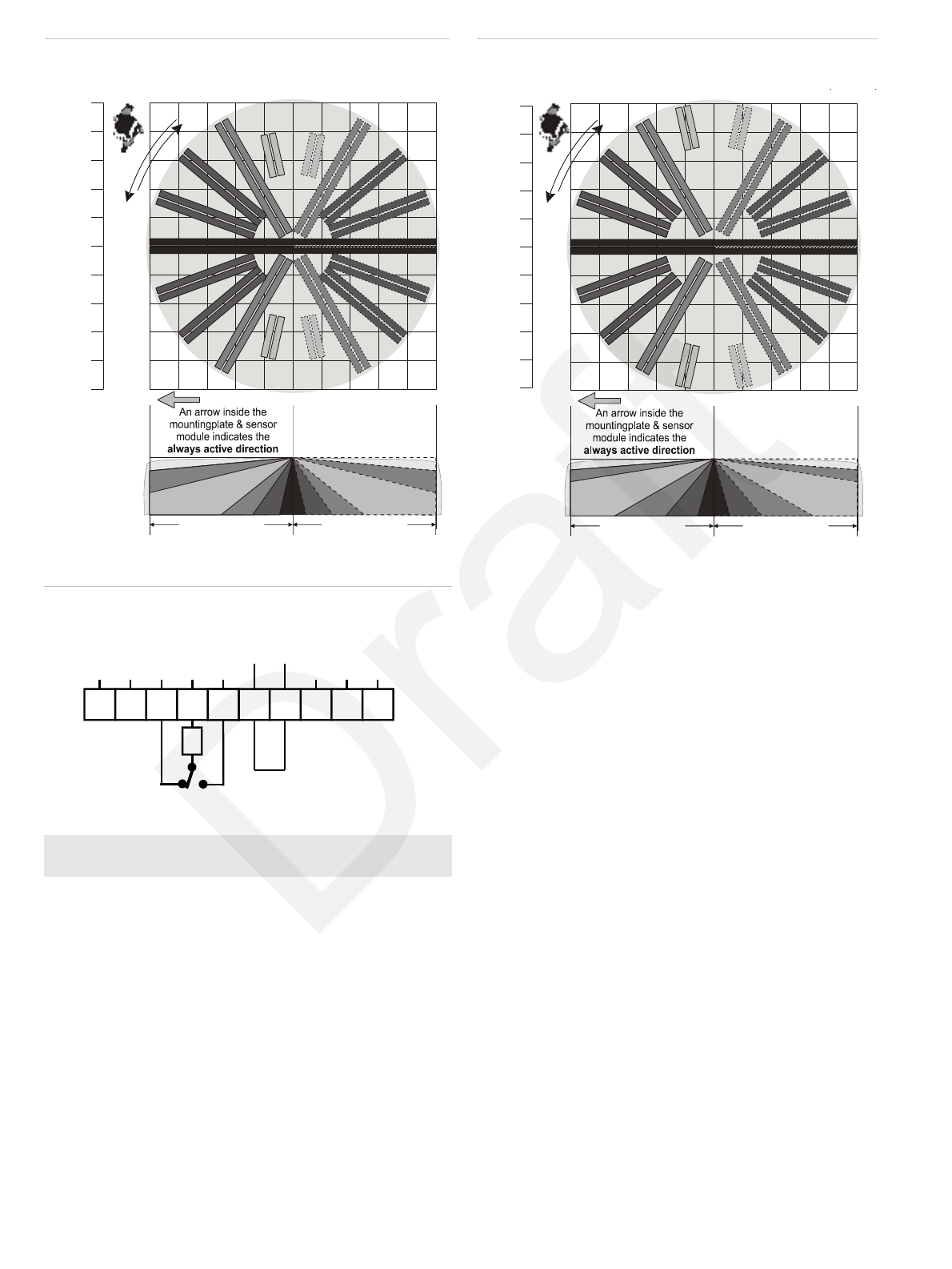
Shaded area is shunted
when switch 4 is in
position
“ON”
Floor pattern at mounting heights
between 2.5 and 3.0 m (8 2 and 9 ft. in.
10 m
(32 ft. 10 in.)
8 m
(26 ft. 3 in.)
6 m
(19 ft. 8 in.)
4 m
(13 ft. 2 in.)
2 m
(6 ft. 7 in.)
0 m
2 m
(6 ft. 7 in.)
4 m
(13 ft. 2 in.)
6 m
(19 ft. 8 in.)
8 m
(26 ft. 3 in.)
10 m
(32 ft. 10 in.)
2.5 3 m-
(8 ft. 2 in. - 9 ft. 10 in.)
10 m
(32 ft. 10 in.)
10 m
(32 ft. 10 in.)
0 m
6
1
1
2
3
4
5
6
7
8
9
9
8
7
6
5
4
3
2
Shaded area is shunted
when switch 4 is in
position
“ON”
Floor pattern at mounting heights above
3.0 m (9 10 ) ft. in.
10 m
(32 ft. 10 in.)
8 m
(26 ft. 3 in.)
6 m
(19 ft. 8 in.)
4 m
(13 ft. 2 in.)
2 m
(6 ft. 7 in.)
0 m
2 m
(6 ft. 7 in.)
4 m
(13 ft. 2 in.)
6 m
(19 ft. 8 in.)
8 m
(26 ft. 3 in.)
10 m
(32 ft. 10 in.)
> 3 m
(> 9 ft. 10 in.)
10 m
(32 ft. 10 in.)
10 m
(32 ft. 10 in.)
0 m
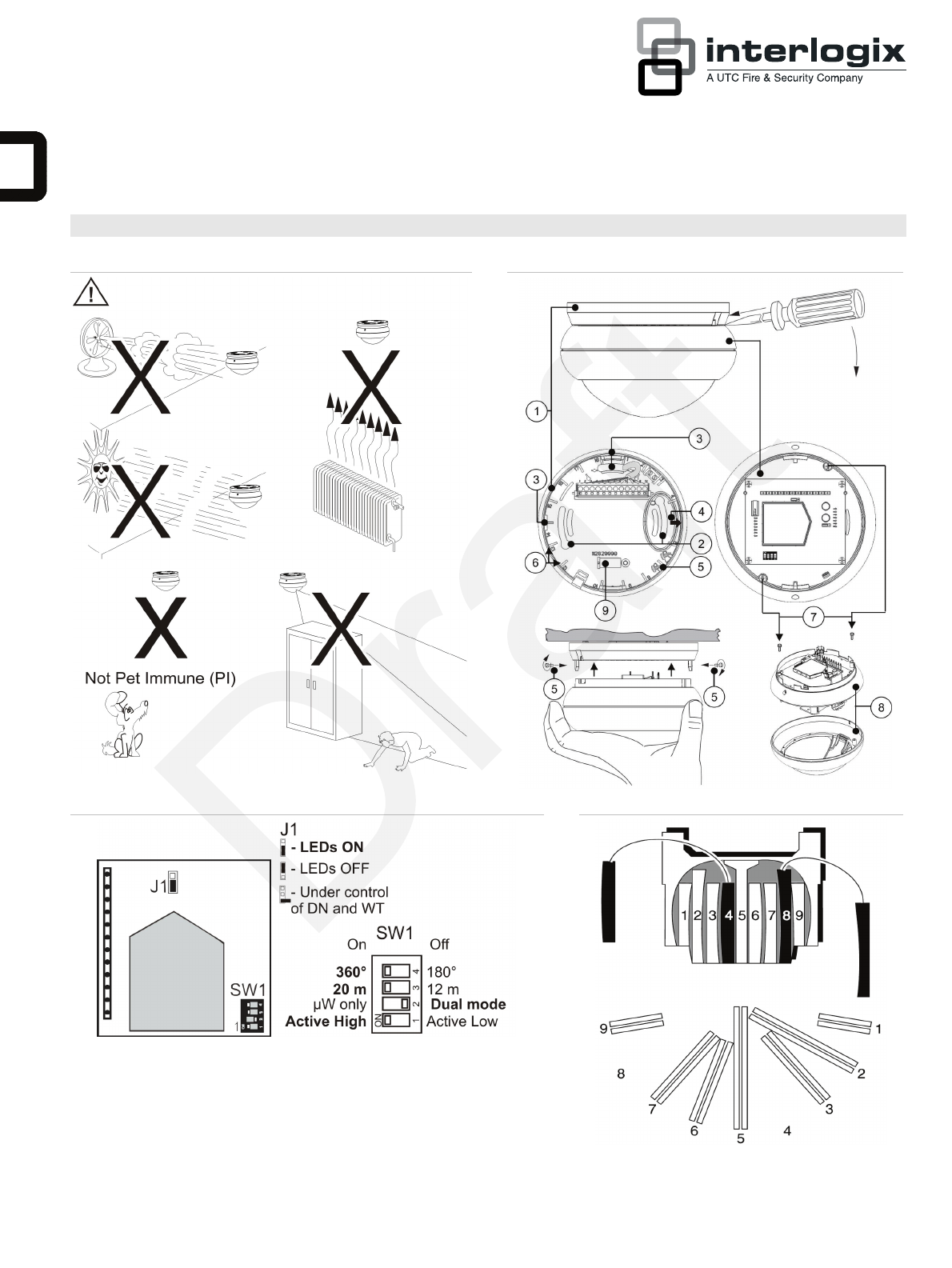
7 • Do not place objects in front of the detector that may
prevent a clear line of sight (Figure 1).
1 2
3
4
1
5
6
7
8
9
10
0V +12V
NC
C
NO
SpareD/N
WT
Tamper
Alarm
33R
DD669-U
’
• Mount detectors at least 6 m (19 ft. 8 in.) apart, and use
the short-range setting to avoid interference.
The dual technology processing of this detector is very
resistant to false alarm hazards. However, avoid potential
causes of instability, such as:
PIR hazards (Figure 1)
• Direct sunlight on the detector
• Heat sources within the detector field of view
• Strong air draughts onto the detector
• Animals in the field of view
• Obscuring the detector field of view with large objects,
such as furniture
EN: Installation Sheet Microwave hazards
• Mounting surface susceptible to vibrations
Introduction • Metal surfaces reflecting microwave energy
The DD669-U is a dual motion sensors. It has the patented
Range Controlled Radar technology.
• Water movement through plastic pipes
• Moving or vibrating objects like fans, heating or air-
conditioning ducts
Installation guidelines We recommend that the detector is regularly walk tested and
checked at the control panel.
The detector can be mounted to a ceiling. Use the following
guidelines to determine the best location to install the detector:
Installing the detector
• Mount the detector so the expected movement of an
intruder is across the detection pattern (Figures 5 and 6). 1. Lift off mounting plate (see Figure 2, item 1).
2. Fasten the mounting plate to the ceiling in the required
position using mounting holes (see Figure 2, item 2).
Specified mounting height: min. 2.5 m (8 ft. 2 in.), max.
5.0 m (16 ft. 5 in.). Specified screws: DIN 7996, 4 mm.
• Mount the detector at a stable surface at a height between
2.5 m (8 ft. 2 in.) and 5.0 m (16 ft. 5 in.).
• Do not mount the detector within 0.5 m (1 ft. 8 in.) of
metallic objects or within 1.5 m (4 ft. 11 in.) of fluorescent
lights. 3. The detection pattern can be adjusted by up to ±15°
(max 30°) by rotation of the mounting plate prior to
tightening the screws.
2 / 4 P/N 146446999-1 • REV 00.04 • ISS 17MAR11
4. Wire the detector (see Figures 2 and 7).
UL/cUL installations: All wiring must be made according
to National Electrical Code, NFPA70, and CSA C22.1,
Canadian Electrical Code Part I, Safety Standards for
electrical Installations.
Increase of mounting heights beyond the specified 2.5 to
5.0 m (8 ft. 2 in. to 16 ft. 5 in.) will reduce sensitivity.
Range varies from 12 to 14 meter (39 ft. 4 in. to 45 ft.
11 in.) in short range and 20 to 22 meter (65 ft. 7 in. to
72 ft. 2 in.) in long range depending on the mounting
height.
Note: The arrow (Figure 2, item 4) indicates the centre
curtain direction and the active direction when switch 4 is
OFF.
5. Select the desired jumper and DIP switch settings (see
Figure 3). See section “Setting the detector” below for
more information.
6. To screw the sensor module to the mounting plate, use the
screws that are placed for transport in the mounting plate
(see Figure 2, item 5).
The curtain directions 1 through 9 clockwise, are indicated on
the mounting plate (see Figure 2, item 6). Curtain number 5 is
the centre curtain.
Selecting the coverage patterns
For access to the mirror undo screws (Figure 2, item 7) and
open the sensor module (Figure 2, item 8). Mask the
appropriate mirror curtains with the adhesive labels provided
and reassemble the sensor module (see Figure 8 for example).
Setting the detector
See Figure 3 for the jumper locations in the detector.
J1: Setting LEDs
On: Enables both LEDs on the detector at all times (factory
default).
Off: Disables both LEDs on the detector at all times.
Removed: Puts both LEDs under the control of the Walk Test
and Day/Night input. This activates the memory feature of the
detector. When the detector is Disarmed and the input Walk
Test is disabled, the microwave section is turned off for
DD669-U. In this configuration the detector operates as a PIR
only.
SW 1: Polarity setting of the control voltage (CV)
On: Active High. Provides the standard UTC Fire & Security
logic with “Active High” logic to enable Walk Test (WT),
Day/Night (D/N), and Remote Test inputs (factory default).
Off: Active Low. Provides “Active Low” logic to enable Walk
Test (WT), Day/Night (D/N) and Remote Test inputs.
SW 2: µW only / Dual mode
On: µW only mode. Consequently the PIR circuitry is switched
off and the detector will only signal alarms caused by the
microwave circuitry.
Off: Dual mode. In dual mode the detector signals an alarm
when both technologies (microwave and PIR) have identified a
target moving in the protected area (factory default).
SW 3: Detector range
The microwave can be selected between 20 ± 0.5 m, and
12 ± 0.5 m (65 ft. 7 in. ± 1 ft. 8 in., and 39 ft. 4 in. ± 1 ft. 8 in.)
Note: Only the microwave range will be reduced, not the PIR
section.
SW 4: Detection coverage
The detection coverage can be selected between 360 degrees
for normal application, and 180 degrees for special
applications.
Note: Only the coverage of the PIR will be adjusted.
Walk testing the detector
The DD669-U provides a walk test mode for testing the
detectors operation and coverage pattern if the detector is set
to LED’s disabled. To walk test the detector, remove the supply
voltage and apply it back on. The walk test mode can be
started once the startup sequence has completely finished
(LED flashes for 45 seconds). The unit stays in walk test mode
for 30 minutes. The detector returns to normal operating mode
after the walk test mode times out.
Green mode
The detector can be programmed in several ways to minimize
the exposure of microwave radiation to human and animal,
although the detector is already sending microwave signal on a
very low power level.
The detector will switch the microwave section off for 3 minutes
after a dual alarm. The detector is in PIR only during this timer.
Settings option 1 J1: Off
SW 2: Off
Settings option 2 J1: Removed
SW 2: Off
System in Armed status
The microwave section is switched off and the detector
operates in PIR mode only.
Setting J1: Removed
SW 2: Off
System in Disarmed status
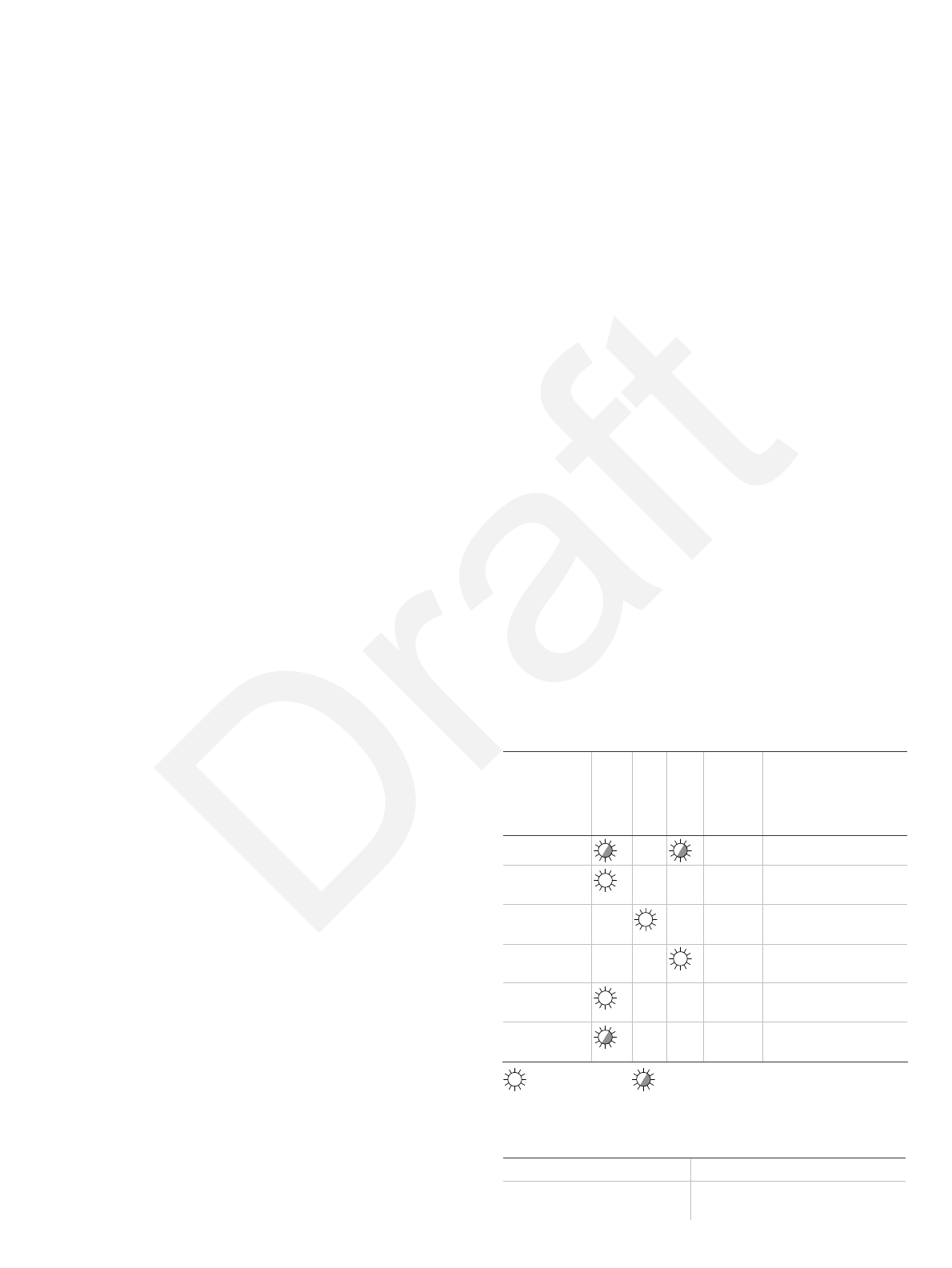
System Walk Test Disabled
LED indication
Red [1]
Green [1]
Yellow [1]
Alarm relay
To reset
Start up Closed Automatically after 45 s
Low voltage Open
(Alarm)
Apply correct voltage
PIR intruder
alarm
Automatically after 3 s
Microwave
intruder alarm
Automatically after 3 s
(Dual) motion
intruder alarm Open
(Alarm)
Automatically after 3 s
Latched PIR
(Memory) Switch to Night mode
Continuously on Normal blinking (1 Hz)
[1] Tri-colour LED.
Specifications
Detector Dual
Range diameter (selectable) 20 ±0.5 m (65 ft. 7 in. ± 1 ft. 7 in.)
or 12 ±0.5 m (39 ft. 4 in. ± 1 ft. 7 in.)
P/N 146446999-1 • REV 00.04 • ISS 17MAR11 3 / 4

Viewing angle (selectable) 360 degrees or 180 degrees
Optical 2 x 9 curtains
Microwave frequency 5.8 GHz
Max microwave output at 1 m 0.003 μW/cm²
Memory Yes
Input power 9 to 15 VDC (12 V nominal)
Peak-to-peak ripple t 12 VDC) 2 V (a
Detector start-up time 45 s
Normal current consumption 12 mA
Current consumption in Alarm 10 mA
Maximum current consumption 15 mA
Mounting height 2.5 to 5.0 m (8 ft. 2 in. to 16 ft. 5 in.)
Target speed range 0.3 to 3.0 m/s (1 ft./s to 9 ft. 10 in./s)
Alarm (NC) / Tamper relay
characteristic
80 mA, 30 VDC, Form C
Pry-off tamper (not evaluate
by UL/cUL)
d Optional
Alarm time 3 s
Operating temperature 0 to 49°C (32 to 120°F)
Dimensions ( x H) 8 x 92 mm ( 5.43 in. x 13
3.62 in.)
Relative humidity max. 95%
Weight z.) 255 g (9 o
IP/IK rating IP30 IK02
The product must be connect ed burglar system
ompatible control unit or power supply unit, which provides a
e
orporation, Inc.
MN 55112-6943, USA
ed to a list
c
minimum 4 hours of standby power.
Perform walk test at least one per year.
Use only a listed power-limited supply.
Certification and complianc
Manufacturer UTC Fire & Security Americas C
1275 Red Fox Rd., Arden Hills,
Authorized EU manufacturing representative:
UTC Fire & Security B.V.
Kelvinstraat 7, 6003 DH Weert, Netherlands
Certification
FCC
Compliance
This device complies with Part 15 of the FCC rules.
Oper on is subject to the following two conditions:
.
FCC
ati
1. This device may not cause harmful interference
2. This device must accept any interference
received, including interference that may cause
undesired operation.
ID: YFYDD669-U
2002 e): Products marked with
sposed of as unsorted
/96/EC (WEEE directiv
this symbol cannot be di
municipal waste in the European Union. For proper
recycling, return this product to your local supplier
upon the purchase of equivalent new equipment, or
dispose of it at designated collection points. For more
information see: www.recyclethis.info.
Contact in
For contact information see our Web site:
utcfireandsecurity.com.
formation
4 / 4 P/N 146446999-1 • REV 00.04 • ISS 17MAR11