UTStarcom Korea Technologies UM100 Tri-Band CDMA/EVDO USB Modem User Manual 080111 UM100C M cricKet indd
UTStarcom Korea Technologies Ltd. Tri-Band CDMA/EVDO USB Modem 080111 UM100C M cricKet indd
UserManual.wiki
>
UTStarcom Korea Technologies
>
UM100 User Manual
Users Manual
Navigation menu
Upload a User Manual
Namespaces
Wiki Guide
HTML
PDF
Info
Views
User Manual
Discussion / Help
Navigation
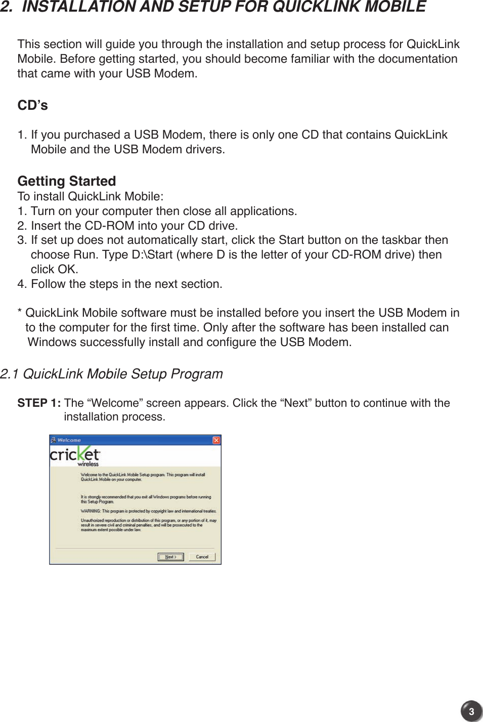
![21.5 Product Features- Power management: The UM100C utilizes power management and system overhead reduction functions provided by the USB interface for maximum power savings.- Antenna design: Efficient, innovative design optimizes data transfer rate and sensitivity to network signals.- Extension Y Cable connector: Simply insert the USB connector into the USB port of your computer to deliver a power boost, increased RF performance, and to solve clearance issues.- USB Modem that supports Type A USB Port interface.- Supports North American PCS (1900 MHz), Cellular (800 MHz) and Aws (Tx 1700MHZ, Rx 2100MHZ) bands.- Utilizes QUALCOMM MSM6801 A chip set.- Supports 3G network technologies.- Average Data Rate: Upto 3.1Mbps peak data down rate download, up to 1.8Mbps peak data rate. *Actual data rate can be varied by user environment.- Supports Windows 2000, XP and Vista systems with installed host software and driver.- Compatible with Mac OSX 10.3.9 or higher.1.6 Product Handling - Do not put any adhesive label on the USB connector. It may leave a sticky residue that can cause problems inside the PC USB port.- The UM100C USB device should easily slide into the USB port. Do not force the UM100C into the USB port as it may cause damage to the modem and/or the port.- Keep the UM100C in a dry and clean place. (Storage temperature: -22°F to 149°F [- 30°C to 65°C]). Keep your device away from liquids, dust and excessive heat. 1.7 Configuration To use the UM100C, you should install the software included in the installation CDand configure the UM100C USB device. See the next section for more information on software installation and USB device configuration.](https://usermanual.wiki/UTStarcom-Korea-Technologies/UM100/User-Guide-907658-Page-4.png)
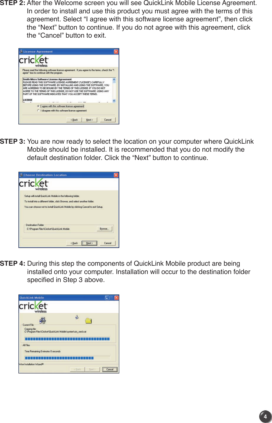
![25241) Unplug or Eject Hardware with Windows 2000 • As shown in the above figure, two “NEC PCI to USB Open Host Controller” options will be displayed in the Hardware devices list of Win2000. However, one of them is disabled and marked with “V”. Select the device with no “V” mark. If you select it and click the “Stop” button, the following window will appear: • Select either of the “NEC PCI to USB Open Host Controller” and click the [OK] button. • The dialog box above will appear. Click the [OK] button.](https://usermanual.wiki/UTStarcom-Korea-Technologies/UM100/User-Guide-907658-Page-27.png)
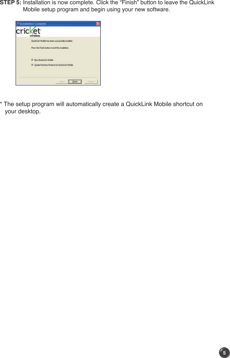
![2726 • Then, the above window will appear. It is now safe to unplug the UM100C.2) Unplug or Eject Hardware with Windows XP • As shown above, only one “NEC PCI to USB Open Host Controller” option will be displayed in Windows XP. Select “NEC PCI to USB Open Host Controller” and click the “Stop” button. • Then, two “NEC PCI to USB Open Host Controller” options will be displayed. Select either one of them and click the [OK] button.](https://usermanual.wiki/UTStarcom-Korea-Technologies/UM100/User-Guide-907658-Page-28.png)
![2726 • Click the [Close] button. It is now safe to unplug the UM100C.3) Unplug or Eject Hardware with Windows Vista • As shown above, only one “NEC PCI to USB Open Host Controller” option will be displayed in Windows Vista. Select “NEC PCI to USB Open Host Controller” and click the “Stop” button. • Then, two “NEC PCI to USB Open Host Controller” options will be displayed. Select one of them and click the [OK] button.](https://usermanual.wiki/UTStarcom-Korea-Technologies/UM100/User-Guide-907658-Page-29.png)
![2928 • Click the [Close] button. It is now safe to unplug the UM100C.5.3.5 Remove the UM100C from your laptop • Remove the UM100C from your laptop. When removing the UM100C, always grip the top and bottom of the modem and push/pull carefully.AB#1#2](https://usermanual.wiki/UTStarcom-Korea-Technologies/UM100/User-Guide-907658-Page-30.png)
![29285.3.6 Using the USB Modem Extension Y Cable • The UM100C Modem package includes an extension USB Y-shaped cable. Although the Y cable is not required for use with your UM100C Modem, it offers increased performance for your UM100C Modem under certain operating conditions. Simply insert the USB connector into the USB port of your computing device to deliver power boost, increased RF performance, and to solve clearance issues.Using the USB Modem Extension Y Cable:1) Plug the single end of the Y-shaped cable into the UM100C Modem. [A]2) Depending on the condition you are trying to solve (power boost, increased RF performance, or clearance issues), plug either one of the two connected ends of the USB modem extension Y cable into the Type A USB port(s) on your computer. [B]Note: The USB modem extension Y cable connector labeled #1, is the primary data power cable used to either extend the UM100C modem away from your computer allowing you to locate the modem in a more optimum signal location or solve any computer USB port clearance issues. The USB modem extension Y cable connector labeled #2, is a power boost Y cable and must be used with connector #1 to provide the modem up to 1Amp of current for use in weaker signal areas.3) The device is connected to and powered by the computer as soon as the USB Y cable is plugged properly into the appropriate Type A USB port(s).4) Click Connect.AB#1#2](https://usermanual.wiki/UTStarcom-Korea-Technologies/UM100/User-Guide-907658-Page-31.png)