UTStarcom Korea Technologies UTS-EA7H75B Wireless Local Loop Fixed Terminal User Manual Cover
UTStarcom Korea Technologies Ltd. Wireless Local Loop Fixed Terminal Cover
UserManual.wiki
>
UTStarcom Korea Technologies
>
UTS-EA7H75B User Manual
>
Manual 5
Contents
1.
Manual 1
2.
Manual 2
3.
Manual 3
4.
Manual 4
5.
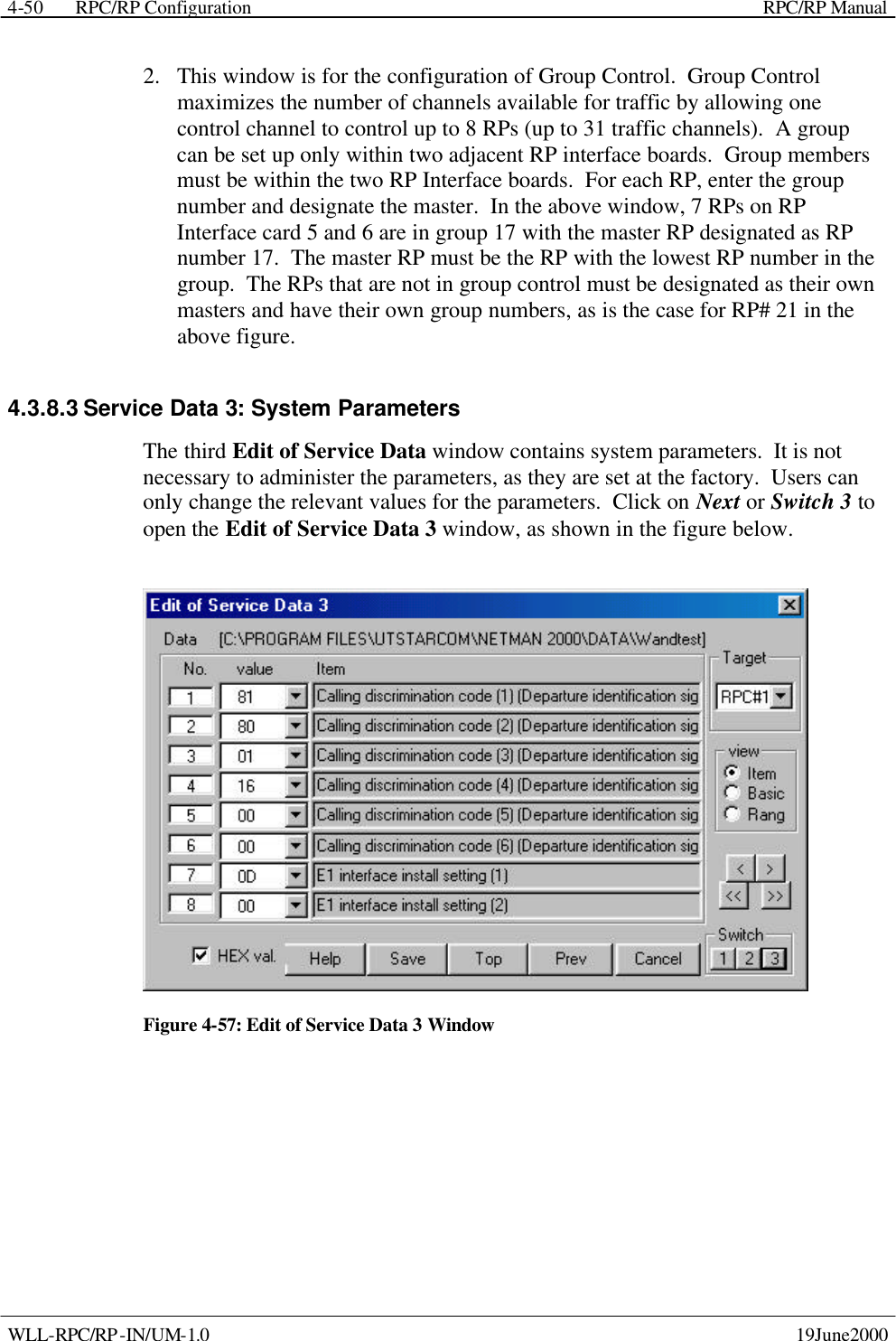
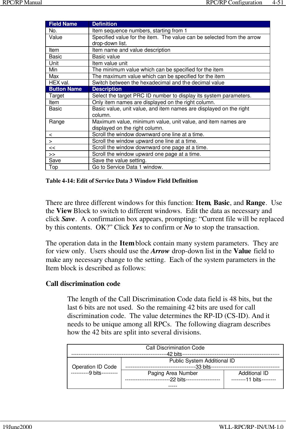
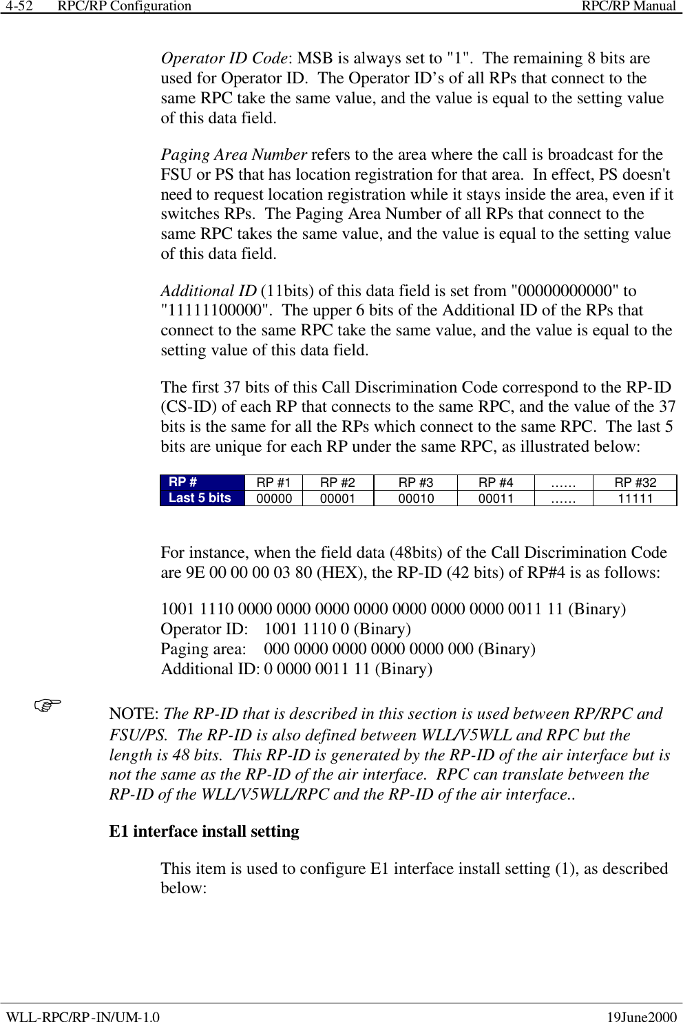
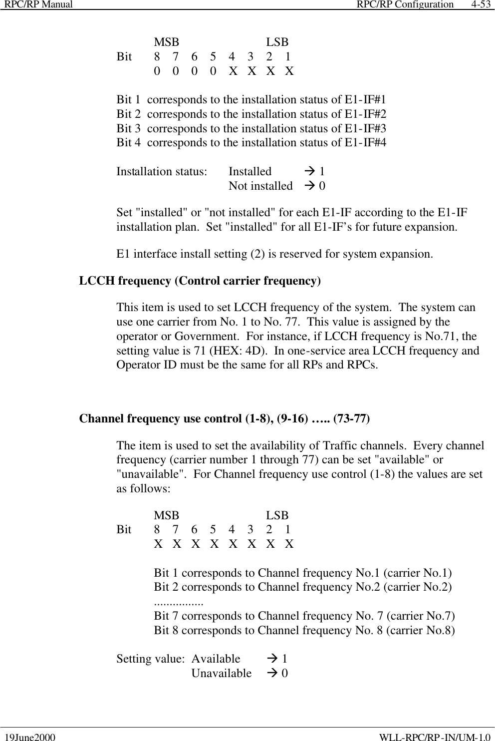
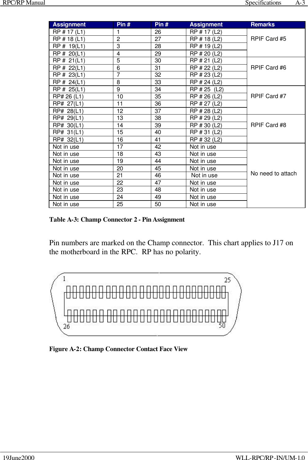
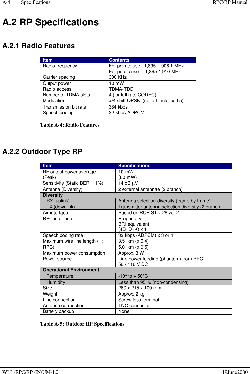
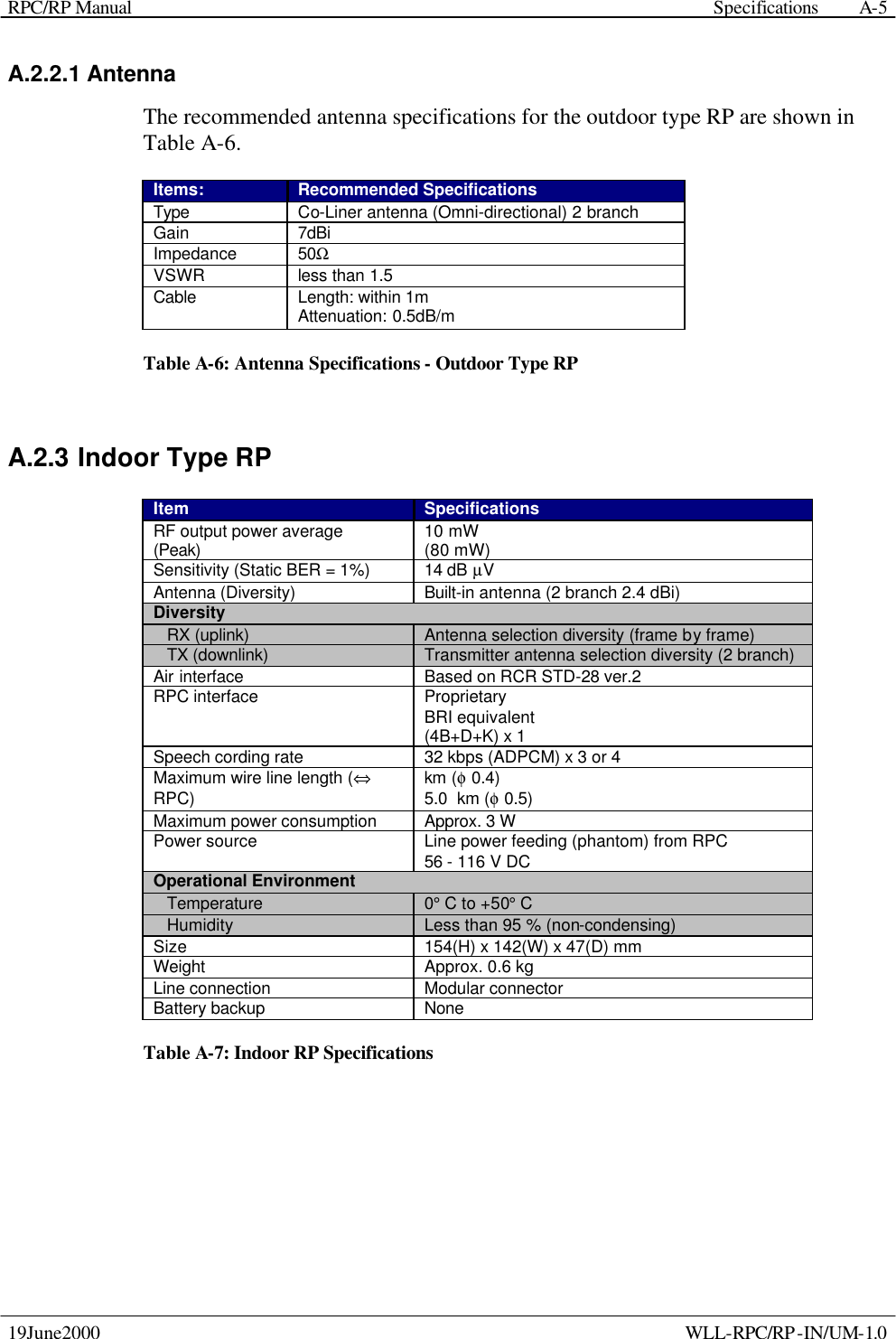
Manual 5
6.
RF manual statement from mfg
Manual 5
Navigation menu
Upload a User Manual
Namespaces
Wiki Guide
HTML
PDF
Info
Views
User Manual
Discussion / Help
Navigation