UTStarcom Korea Technologies UTS-EA7H75B Wireless Local Loop Fixed Terminal User Manual Cover
UTStarcom Korea Technologies Ltd. Wireless Local Loop Fixed Terminal Cover
Contents
Manual 5
RPC/RP Configuration RPC/RP Manual
WLL-RPC/RP-IN/UM-1.0 19June2000
4-
46
4.3.7 Copy Data
This function is used to copy the operating data from the ACT SDM to the SBY
SDM. The automatic SDM switching is not supported for this function.
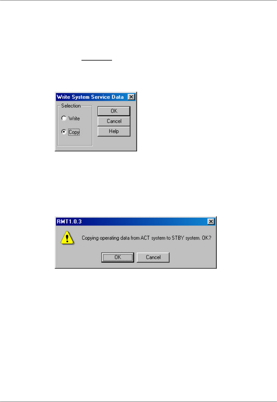
1. From the Configure main menu, click Service Data, and then Write Data.
This opens the Write System Service Data window, as shown in the figure
below.
Figure 4-52: Write System Service Data Window
2. Click the Copy radio button and then click OK. A confirmation dialog box
appears, as illustrated in the figure below. Click OK to confirm the copying
command.
Figure 4-53: Confirmation Dialog Box
4.3.8 Edit Data
RPC operation data contain three categories:
1. Service data 1: RP installation
2. Service data 2: Group control configuration
3. Service data 3: System parameters
RPC/RP Manual RPC/RP Configuration
19June2000 WLL-RPC/RP-IN/UM-1.0
4-
47
Use this function to edit an existing operation data file while the RPC is
operating.
F NOTE: Operation data must be edited locally in a file, and then downloaded to
the system.
4.3.8.1 Service Data 1: RP Installation
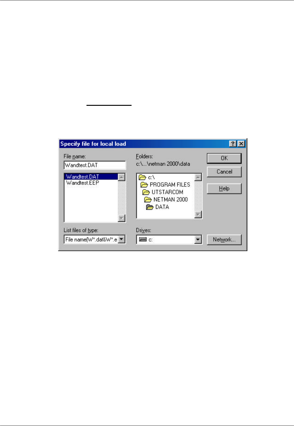
1. From the Configuration main menu, click the Service Data option, and then
the Edit Data option. This brings up the Specify File for Edit window, as
shown in the figure below.
Figure 4-54: Specify file for Edit Window
2. Select the target .dat or .eep file and click Open. The system edits all the files
with any one of the two suffixes. The Edit of Service Data 1 window opens,
as shown in the figure below.
RPC/RP Configuration RPC/RP Manual
WLL-RPC/RP-IN/UM-1.0 19June2000
4-
48
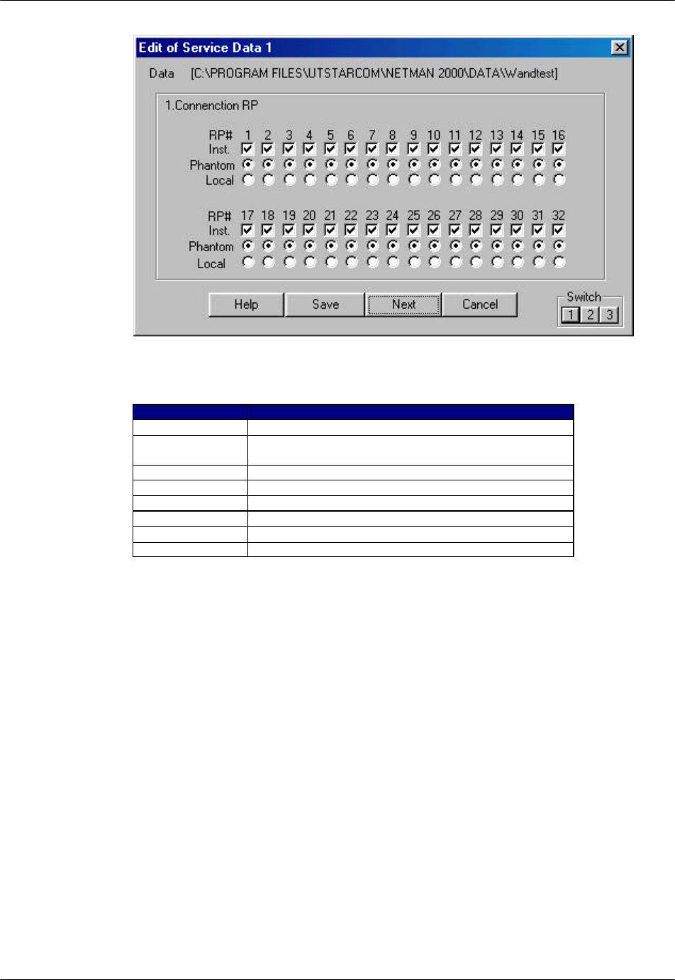
Figure 4-55: Edit of Service Data 1 Window
Field Name Description
RP# RP ID number
Inst. Set “installed” or “not installed” for RPs according to
RP installation plan.
Phantom The power is supplied by the RPC.
Local The power is supplied by the RP power unit.
Save Save the setting to a local file.
Next Switch to the next Service Data window.
Cancel Cancel the editing.
Switch 1,2,3 Switch to one of the three Service Data windows.
Table 4-12: Edit of Service Data 1 Window Field Description
3. For each installed RP, enter a √ in the Inst. row. For each installed RP,
specify the power source by clicking on either the Phantom button or the
Local button. For WLL, the power source is Phantom. Local is for future
use when the power is 20 milliwatts or higher.
4.3.8.2 Service Data 2: Group Control Configuration
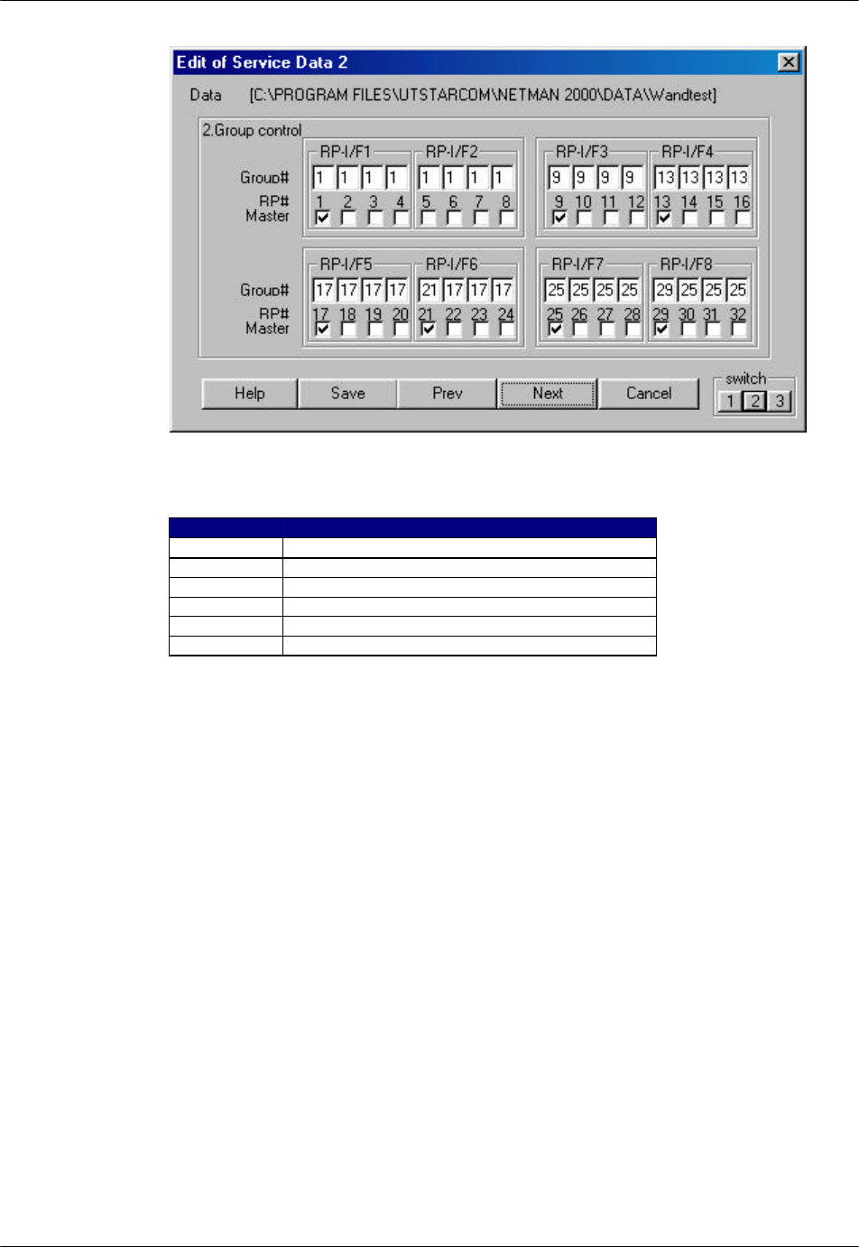
1. To get to the Edit of Service Data 2 window, click Next or Switch 2. The
Edit of Service Data 2 window opens, as shown in the figure below.
RPC/RP Manual RPC/RP Configuration
19June2000 WLL-RPC/RP-IN/UM-1.0
4-
49
Figure 4-56: Edit of Service Data 2 Window
Field Name Description
RP-I/F RP interface ID number
Group # Group ID number
RP# RP ID number
Master Master/Slave status of the RPs
Save Save the Service Data toa a file.
Next Switch to the next window
Table 4-13: Edit of Service Data 2 Window Field Description
F NOTE: RP ID numbers are defined according to the connected physical port
numbers on the RP interface boards, as listed below:
RP-IF#1 port 1 ----- RP#1
RP-IF#1 port 2 ----- RP#2
RP-IF#1 port 3 ----- RP#3
RP-IF#1 port 4 ----- RP#4
RP-IF#2 port 1 ----- RP#5
…..
RP-IF#3 port 1 ----- RP#9
…..
RP-IF#8 port 1 ----- RP#29
RP-IF#8 port 2 ----- RP#30
RP-IF#8 port 3 ----- RP#31
RP-IF#8 port 4 ----- RP#32
RPC/RP Configuration RPC/RP Manual
WLL-RPC/RP-IN/UM-1.0 19June2000
4-
50
2. This window is for the configuration of Group Control. Group Control
maximizes the number of channels available for traffic by allowing one
control channel to control up to 8 RPs (up to 31 traffic channels). A group
can be set up only within two adjacent RP interface boards. Group members
must be within the two RP Interface boards. For each RP, enter the group
number and designate the master. In the above window, 7 RPs on RP
Interface card 5 and 6 are in group 17 with the master RP designated as RP
number 17. The master RP must be the RP with the lowest RP number in the
group. The RPs that are not in group control must be designated as their own
masters and have their own group numbers, as is the case for RP# 21 in the
above figure.
4.3.8.3 Service Data 3: System Parameters
The third Edit of Service Data window contains system parameters. It is not
necessary to administer the parameters, as they are set at the factory. Users can
only change the relevant values for the parameters. Click on Next or Switch 3 to
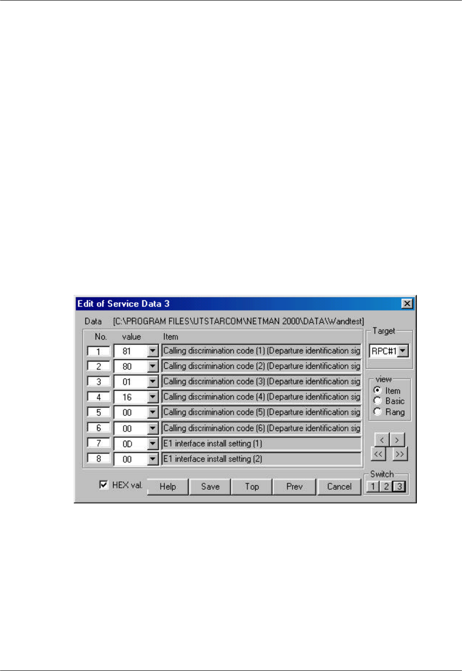
open the Edit of Service Data 3 window, as shown in the figure below.
Figure 4-57: Edit of Service Data 3 Window

RPC/RP Manual RPC/RP Configuration
19June2000 WLL-RPC/RP-IN/UM-1.0
4-
51
Field Name Definition
No. Item sequence numbers, starting from 1
Value Specified value for the item. The value can be selected from the arrow
drop-down list.
Item Item name and value description
Basic Basic value
Unit Item value unit
Min The minimum value which can be specified for the item
Max The maximum value which can be specified for the item
HEX val. Switch between the hexadecimal and the decimal value
Button Name Description
Target Select the target PRC ID number to display its system parameters.
Item Only item names are displayed on the right column.
Basic Basic value, unit value, and item names are displayed on the right
column.
Range Maximum value, minimum value, unit value, and item names are
displayed on the right column.
< Scroll the window downward one line at a time.
> Scroll the window upward one line at a time.
<< Scroll the window downward one page at a time.
>> Scroll the window upward one page at a time.
Save Save the value setting.
Top Go to Service Data 1 window.
Table 4-14: Edit of Service Data 3 Window Field Definition
There are three different windows for this function: Item, Basic, and Range. Use
the View Block to switch to different windows. Edit the data as necessary and
click Save. A confirmation box appears, prompting: “Current file will be replaced
by this contents. OK?” Click Yes to confirm or No to stop the transaction.
The operation data in the Item block contain many system parameters. They are
for view only. Users should use the Arrow drop-down list in the Value field to
make any necessary change to the setting. Each of the system parameters in the
Item block is described as follows:
Call discrimination code
The length of the Call Discrimination Code data field is 48 bits, but the
last 6 bits are not used. So the remaining 42 bits are used for call
discrimination code. The value determines the RP-ID (CS-ID). And it
needs to be unique among all RPCs. The following diagram describes
how the 42 bits are split into several divisions.
Call Discrimination Code
-----------------------------------------------------42 bits------------------------------------------------------
Public System Additional ID
---------------------------------------33 bits--------------------------------------
Operation ID Code
----------9 bits--------- Paging Area Number
-------------------------22 bits-------------------
-----
Additional ID
--------11 bits--------

RPC/RP Configuration RPC/RP Manual
WLL-RPC/RP-IN/UM-1.0 19June2000
4-
52
Operator ID Code: MSB is always set to "1". The remaining 8 bits are
used for Operator ID. The Operator ID’s of all RPs that connect to the
same RPC take the same value, and the value is equal to the setting value
of this data field.
Paging Area Number refers to the area where the call is broadcast for the
FSU or PS that has location registration for that area. In effect, PS doesn't
need to request location registration while it stays inside the area, even if it
switches RPs. The Paging Area Number of all RPs that connect to the
same RPC takes the same value, and the value is equal to the setting value
of this data field.
Additional ID (11bits) of this data field is set from "00000000000" to
"11111100000". The upper 6 bits of the Additional ID of the RPs that
connect to the same RPC take the same value, and the value is equal to the
setting value of this data field.
The first 37 bits of this Call Discrimination Code correspond to the RP-ID
(CS-ID) of each RP that connects to the same RPC, and the value of the 37
bits is the same for all the RPs which connect to the same RPC. The last 5
bits are unique for each RP under the same RPC, as illustrated below:
RP # RP #1 RP #2 RP #3 RP #4 …… RP #32
Last 5 bits 00000 00001 00010 00011 …… 11111
For instance, when the field data (48bits) of the Call Discrimination Code
are 9E 00 00 00 03 80 (HEX), the RP-ID (42 bits) of RP#4 is as follows:
1001 1110 0000 0000 0000 0000 0000 0000 0000 0011 11 (Binary)
Operator ID: 1001 1110 0 (Binary)
Paging area: 000 0000 0000 0000 0000 000 (Binary)
Additional ID: 0 0000 0011 11 (Binary)
F NOTE: The RP-ID that is described in this section is used between RP/RPC and
FSU/PS. The RP-ID is also defined between WLL/V5WLL and RPC but the
length is 48 bits. This RP-ID is generated by the RP-ID of the air interface but is
not the same as the RP-ID of the air interface. RPC can translate between the
RP-ID of the WLL/V5WLL/RPC and the RP-ID of the air interface..
E1 interface install setting
This item is used to configure E1 interface install setting (1), as described
below:

RPC/RP Manual RPC/RP Configuration
19June2000 WLL-RPC/RP-IN/UM-1.0
4-
53
MSB LSB
Bit 8 7 6 5 4 3 2 1
0 0 0 0 X X X X
Bit 1 corresponds to the installation status of E1-IF#1
Bit 2 corresponds to the installation status of E1-IF#2
Bit 3 corresponds to the installation status of E1-IF#3
Bit 4 corresponds to the installation status of E1-IF#4
Installation status: Installed à 1
Not installed à 0
Set "installed" or "not installed" for each E1-IF according to the E1-IF
installation plan. Set "installed" for all E1-IF’s for future expansion.
E1 interface install setting (2) is reserved for system expansion.
LCCH frequency (Control carrier frequency)
This item is used to set LCCH frequency of the system. The system can
use one carrier from No. 1 to No. 77. This value is assigned by the
operator or Government. For instance, if LCCH frequency is No.71, the
setting value is 71 (HEX: 4D). In one-service area LCCH frequency and
Operator ID must be the same for all RPs and RPCs.
Channel frequency use control (1-8), (9-16) ….. (73-77)
The item is used to set the availability of Traffic channels. Every channel
frequency (carrier number 1 through 77) can be set "available" or
"unavailable". For Channel frequency use control (1-8) the values are set
as follows:
MSB LSB
Bit 8 7 6 5 4 3 2 1
X X X X X X X X
Bit 1 corresponds to Channel frequency No.1 (carrier No.1)
Bit 2 corresponds to Channel frequency No.2 (carrier No.2)
................
Bit 7 corresponds to Channel frequency No. 7 (carrier No.7)
Bit 8 corresponds to Channel frequency No. 8 (carrier No.8)
Setting value: Available à 1
Unavailable à 0

RPC/RP Configuration RPC/RP Manual
WLL-RPC/RP-IN/UM-1.0 19June2000
4-
54
For instance, if Channel frequency No. 1, 3, 5 are available and Channel
frequency No. 2, 4, 6, 7, 8 are unavailable, the values are set as follows:
Channel frequency use control (1-8): 0001 0101(Binary) (HEX: 15)
Channel frequency use control (9-16) ….. (73-77) are set in the same way.
The previous and the next Channel frequency of LCCH frequency must be
set "Unavailable" for traffic channel to avoid the interference.
Loudness control value (input loudness value)
This item is used to set the RPC input loudness control value, as described
below:
MSB LSB
Bit 8 7 6 5 4 3 2 1
0 0 0 y x x x x
Bit 1-4 (xxxx) are the value of loudness, as listed below:
Real level Bit 4 3 2 1
0 dB à 0 0 0 0
2 dB à 0 0 0 1
4 dB à 0 0 1 0
6 dB à 0 0 1 1
...............
Bit 5 is the value of sign.
Sign Bit 5
à 1
à 0
...................
For instance, if the input loudness of RPC needs to be set to + 8 dB, the
setting value is as follows:
0001 0100 (Binary)
This value is determined in accordance with the system level plan.
Loudness control value (output loudness value)
This item is used to set the RPC output loudness control value, as
described below:

RPC/RP Manual RPC/RP Configuration
19June2000 WLL-RPC/RP-IN/UM-1.0
4-
55
MSB LSB
Bit 8 7 6 5 4 3 2 1
0 0 0 y x x x x
Bit 1-4 (xxxx) are the value of loudness, as listed below:
Real level Bit 4 3 2 1
0 dB à 0 0 0 0
2 dB à 0 0 0 1
4 dB à 0 0 1 0
6 dB à 0 0 1 1
...............
Bit 5 is the value of sign.
Sign Bit 5
à 1
à 0
...................
For instance, if the output loudness of RPC needs to be set to + 8 dB, the
setting value is as follows:
0001 0100 (Binary)
This value is determined in accordance with the system level plan.
Loudness control value (DTMF signal loudness value)
In the case of PS origination, dialing information is transferred as a
message from the PS to the RPC. The RPC generates the DTMF signal
tone according to the received message. This item used for the setting of
output DTMF signal loudness, as described below:
MSB LSB
Bit 8 7 6 5 4 3 2 1
0 0 0 y x x x x

RPC/RP Configuration RPC/RP Manual
WLL-RPC/RP-IN/UM-1.0 19June2000
4-
56
Bit 1-4 (xxxx) are the value of loudness, as listed below:
Real level Bit 4 3 2 1
0 dB à 0 0 0 0
2 dB à 0 0 0 1
4 dB à 0 0 1 0
6 dB à 0 0 1 1
...............
Bit 5 is the value of sign.
Sign Bit 5
à 1
à 0
...................
For instance, if the output loudness of RPC needs to be set to + 8 dB, the
setting value is as follows:
0001 0100 (Binary)
This value is determined in accordance with the system level plan.
DTMF sound sending interval value
In the case of PS origination, dialing information is transferred as a
message from the PS to the RPC. The RPC generates the DTMF signal
tone according to the received message. This item is used for the setting
of DTMF minimum pause of the DTMF signal. The value (unit: msec) is
directly set in the value field.
For instance, if the sending interval time needs to be set to 80 msec, the
setting value is "50" (HEX).
DTMF sound sending time value
In the case of PS origination, dialing information is transferred as a
message from the PS to the RPC. The RPC generates the DTMF signal
tone according to the received message. This item is used for the setting
of DTMF sending time of the DTMF signal. The value (unit: msec) is
directly set in the value field.
For instance, if the sending time needs to be set to 80 msec, the setting
value is "50" (HEX).

RPC/RP Manual RPC/RP Configuration
19June2000 WLL-RPC/RP-IN/UM-1.0
4-
57
Country number 1, 2
This item is used for the setting of Country Code. The Country code is
used to represent the country which assigns the RP identification code.
System type
This item is used for the setting of system type. This system is applicable
for the system. The system type is 3. The coding is "0000 0100" (Binary).
Standby zone selection level
This item is used for the setting of air-interface.
Standby zone hold level
This item is used for the setting of air-interface.
Recalling-type handover process level
This item is used for the setting of air-interface.
Recalling-type handover destination zone selection level
This item is used for the setting of air-interface.
Channel switching FER threshold value
This item is used for the setting of air-interface.
Reservation/Area information report status number
This item is used for the setting of air-interface.
TCH switching-type handover process level
This item is used for the setting of air-interface.

RPC/RP Configuration RPC/RP Manual
WLL-RPC/RP-IN/UM-1.0 19June2000
4-
58
FSU mobility limitation
This item is used for the control of FSU mobility limitation. Depending
on the setting value, one mode might be that RPC reports RP-ID to
WLL/V5WLL for mobility, the other mode might be that RPC doesn't
report RP-ID to WLL/V5WLL for mobility. In the case that RPC reports
RP-ID to WLL/V5WLL, WLL/V5WLL controls FSU mobility in
accordance with the subscriber setting. In the case that RPC doesn't report
RP-ID, FSU mobility isn't limited regardless of the subscriber setting. The
way of setting is as follows,
Bit 8 7 6 5 4 3 2 1
0 0 0 0 0 0 0 0 à The mode that RPC doesn’t report RP-ID
0 0 0 0 0 0 0 1 à The mode that RPC reports RP-ID
4.3.9 Change Data (RP Installation)
Use the procedure in this section to change the operation data for the selected
RPC. The diagrams displayed in this section are very similar to those in the
previous section. The only difference is that there are two configuration windows
instead of three.
1. To change the operation data for an RPC, click the Configuration main menu
and select the Service Data option, then the Change Data option, and then the
RP Installation option. This opens the RP Installation (Group
Composition 1) window, as displayed in the figure below.
F NOTE: Before making any changes to the operation data, be sure to block the
E1/IF and RP/IF. After the setting is modified, the RP/IF will restart itself.
RPC/RP Manual RPC/RP Configuration
19June2000 WLL-RPC/RP-IN/UM-1.0
4-
59
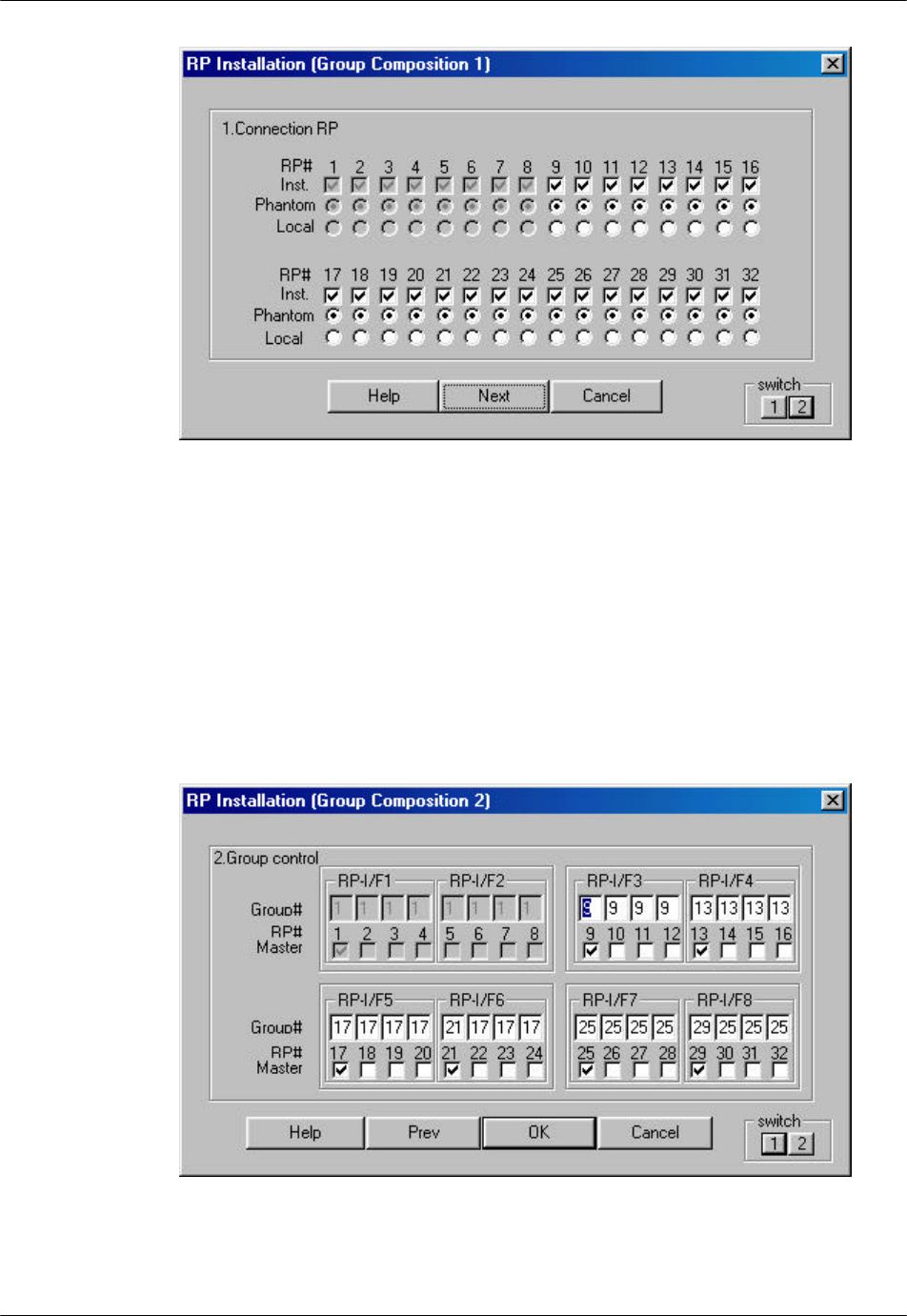
Figure 4-58: RP Installation (Group Composition 1) Window
2. This window is used to configure RP connection. For each installed RP, enter
a √ in the Inst. row. For each installed RP, specify the power source by
clicking on either the Phantom button or the Local button. Phantom means
the power is supplied by the RPC. For WLL, the power source is Phantom.
3. To get to the RP Installation (Group Composition 2) window, click Next or
Switch 2. The RP Installation (Group Composition 2) window is shown in
the figure below.
Figure 4-59: RP Installation (Group Composition 2) Window
RPC/RP Configuration RPC/RP Manual
WLL-RPC/RP-IN/UM-1.0 19June2000
4-
60
4. This window is for the configuration of Group Control. Group Control
maximizes the number of channels available for traffic by allowing one
control channel to control up to 8 RPs (up to 31 traffic channels). Each group
contains two RP Interface boards. Group members must be within the two RP
Interface boards. For each RP, enter the group number and designate the
master. In the above window, 7 RPs on RP Interface boards 5 and 6 are in
group 17 with the master RP designated as RP number 17. The master RP
must be the RP with the lowest RP number in the group. The RPs that are not
in group control must be designated as their own masters and have their own
group numbers, as is the case for RP# 21 in the above figure.
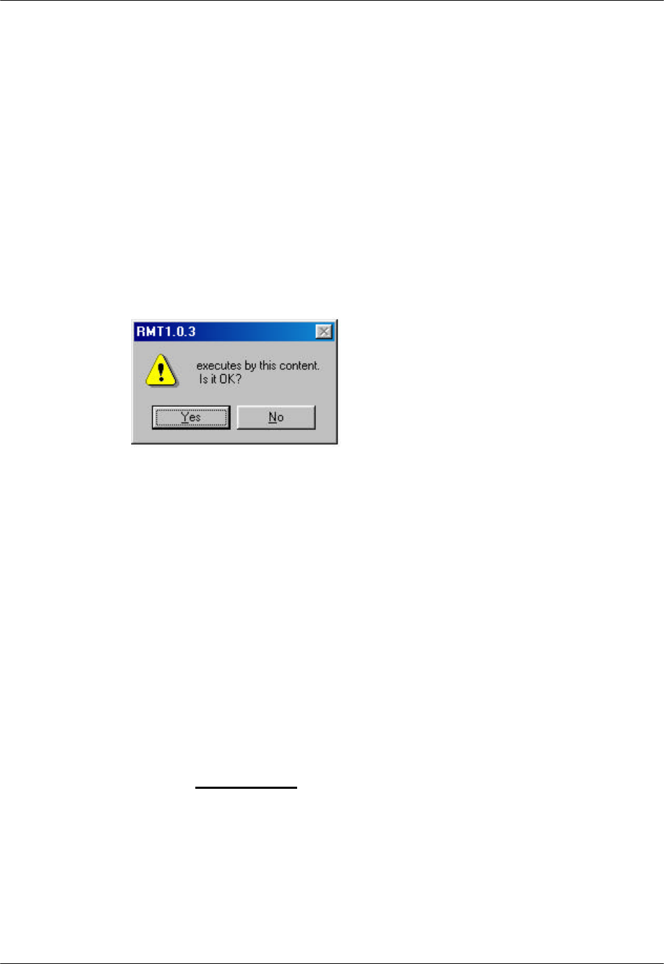
5. After editing the operation data click OK. A dialog box opens for
confirmation, as shown in the figure below.
Figure 4-60: Confirmation Dialog Box
6. Click Yes to confirm, or No to stop the transaction. If the Version
Confirmation window opens when Yes button is clicked, verify that the
version is correct and then click OK.
4.3.10 Change Data (E1-IF Board Installation)
Each RPC can have 4 E1 interface boards to communicate with WLL/V5WLL.
Use the steps in this section to select the target E1 interfaces to be installed or
uninstalled.
1. First use the Blockade option under Unit Control to block the target E1
interfaces.
2. From the Configuration pull-down menu, select Service Data, then Change
Data, and then E1-I/F Board Installation. This opens the E1-I/F Board
Installation window, as shown in the figure below.
RPC/RP Manual RPC/RP Configuration
19June2000 WLL-RPC/RP-IN/UM-1.0
4-
61
Figure 4-61: E1-IF Board Installation
3. Check or uncheck the boxes in front of the target E1 interfaces to be installed
or uninstalled, and click OK.
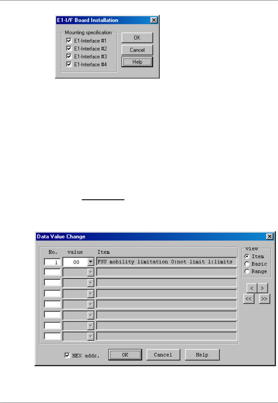
4.3.11 Change Data (Data Value)
Use this function to change the operation data value.
F NOTE: This feature is not recommended. Use with care.
1. From the Configuration main menu, click Service Data, then Change Data,
and then Data Value. The Data Value Change window opens, as illustrated
in the figure below.
Figure 4-62: Data Value Change Window

RPC/RP Configuration RPC/RP Manual
WLL-RPC/RP-IN/UM-1.0 19June2000
4-
62
Field Name Definition
No. Item sequence numbers, starting from 1
Value Specified value for the item. The valid values are displayed in the Item
block and can be selected from the arrow drop-down list.
Item Item name and value description
Basic Basic value
Unit Item value unit
Min The minimum value which can be specified for the item
Max The maximum value which can be specified for the item
HEX addr. Switch between hexadecimal and decimal value
Button Name Description
Item Only item names are displayed on the right column.
Basic Basic value, unit value, and item names are displayed on the right
column.
Range Maximum value, minimum value, unit value, and item names are
displayed on the right column.
< Scroll the window downward one line at a time.
> Scroll the window upward one line at a time.
<< Scroll the window downward one page at a time.
>> Scroll the window upward one page at a time.
OK Implement the command.
Table 4-15: Data Value Change Window Field Description
2. There are three different windows for this function: Item, Basic, and Range.
Use the View block to switch between different windows. Refer to Section
4.3.8.3 for the detailed description for the Value field and the Item block.
3. Make necessary changes and click OK to close the window.
4.4 Manage RPC Alarms
This section discusses several aspects concerning the RPC warning and alarm
history. Through the RPC device manager, we can update and clear the alarm, or
save the alarm history to files for further analysis.
The warning messages are also displayed in the Status View windows for RPCs,
RPs, and interfaces, as described in Section 4.2.4.
4.4.1 Warning Status
The RPC device manager can display currently occurring warnings about the
RPC, RP, E1 interface, and RP interface.
1. On the Main View window, click the RPC R2.4 node. Get connected to the
target RPC.
RPC/RP Manual RPC/RP Configuration
19June2000 WLL-RPC/RP-IN/UM-1.0
4-
63
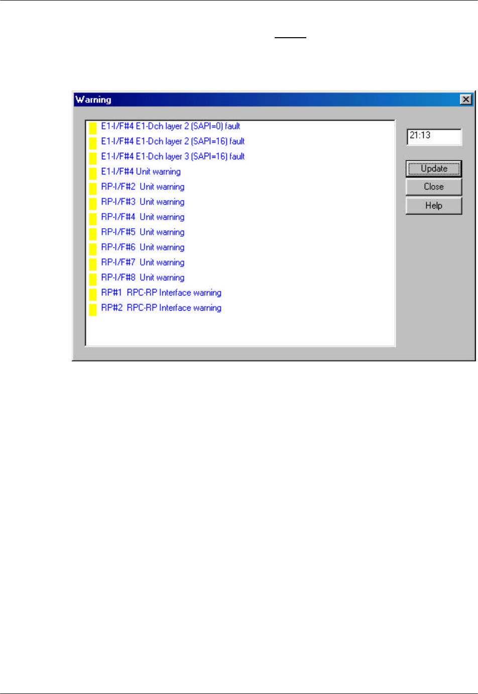
2. To view the RPC warnings, click the Status main menu, and select the
Warning option. The Warning window appears, as displayed in the figure
below. Another way to open the window is to click the Warning button.
Figure 4-63: Warning Window
3. Click the Update button to retrieve the latest information. The color of the
small rectangle in front of each warning message indicates the alarm’s
severity.
• Red - Major Alarm
• Yellow - Minor Alarm
• Green - No Alarm
4. After viewing the warning, click Close to close the window.
4.4.2 Alarm History
The Alarm History option provides access to a chronological log of all the RPC,
RP, interfaces, and synchronization warnings. This log may contain information
useful in diagnosing equipment malfunctions.
RPC/RP Configuration RPC/RP Manual
WLL-RPC/RP-IN/UM-1.0 19June2000
4-
64
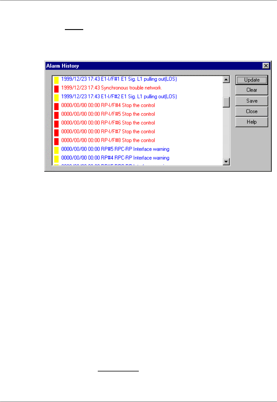
1. To view the log of the Alarm History, select the Alarm History option from
the Status main menu. The Alarm History window appears as shown in the
figure below. Another way to open the window is to click the Fault History
button.
Figure 4-64: Alarm History Window
F NOTE: This log has a capacity of storing 127 messages. When this limit is
reached, the oldest message is deleted when the newest one is added.
2. Click Update to display the historical information. To clear the present alarm
history, click Clear. The contents of this window can be saved to a file for
further analysis. Click the Save button and specify a file name.
3. Click Close to close this window.
4.5 Reset RPC
When an RPC or its other components experience trouble and the problem cannot
be solved, it may be necessary to reset the component. Use the following
procedures to reset an E1 interface, an RP interface, an RP, or an RPC.
F WARNING: Do not directly reset a unit in operation since this will cause active
subscriber calls to be dropped. Before resetting a unit, block the unit temporarily
by resorting to the Configuration à Unit Control à Blockade option. Check
the Channel Status to verify that there are no active calls. Click the Channel
RPC/RP Manual RPC/RP Configuration
19June2000 WLL-RPC/RP-IN/UM-1.0
4-
65
button or click Air Channel on the Unit View window of the RPC window to
open the Channel Status View window. After resetting, unblock the unit.
1. On the Main View window, click the target RPC-DM node and connect to the
RPC. This opens the RPC window.
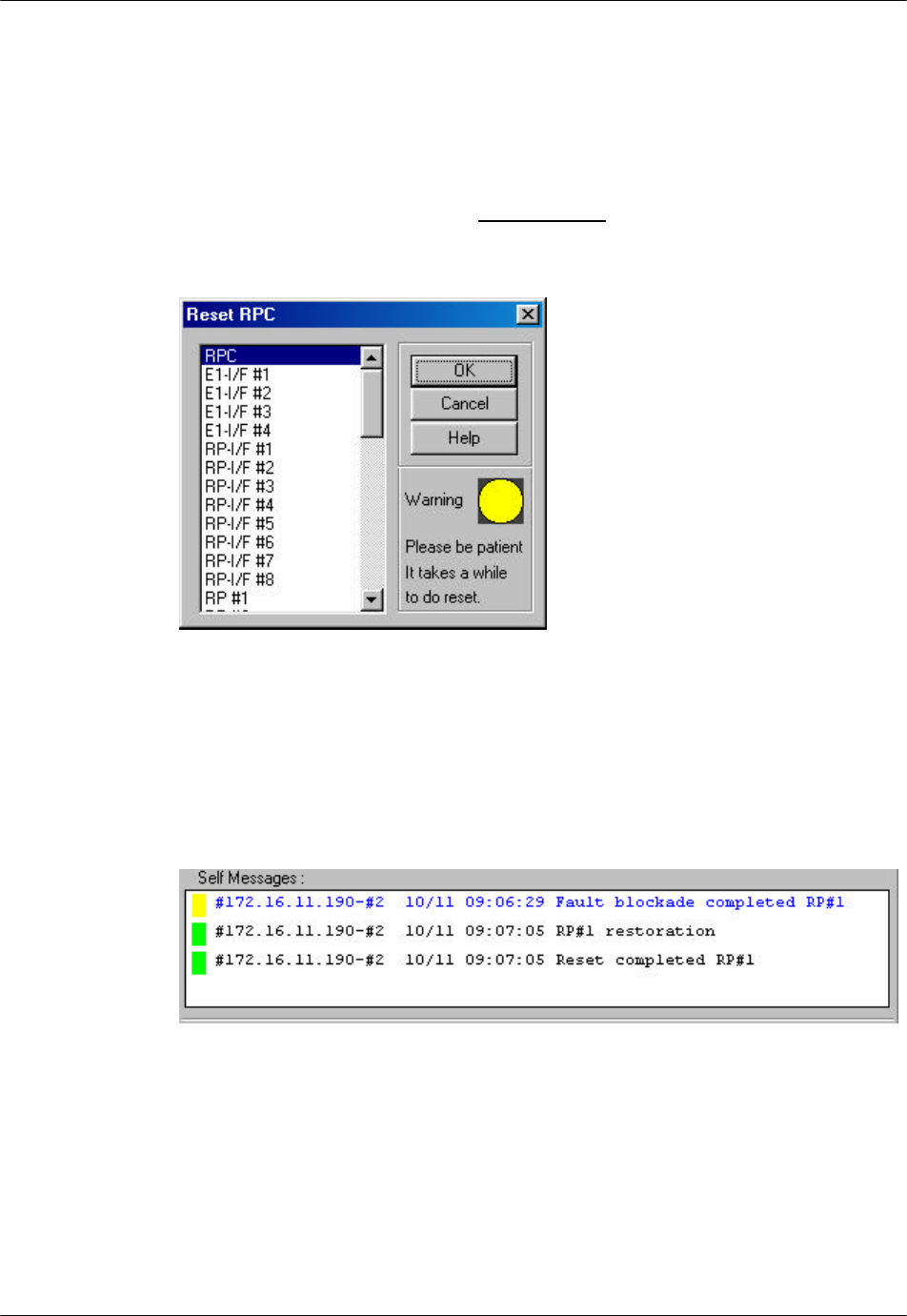
2. Select the Reset option from the Maintenance pull-down menu or click the
Reset button. The Reset window appears, as shown in the figure below.
Figure 4-65: Reset RPC Window
3. Select either an RP, an E1 interface, an RP interface, or the entire RPC. Click
OK. The system resets the unit, returns it to operation, and sends a message to
the Self Messages window. Suppose that the RP#1 of the RPC#2 were reset,
the window would be like the figure below.
Figure 4-66: Self Messages Window for Reset
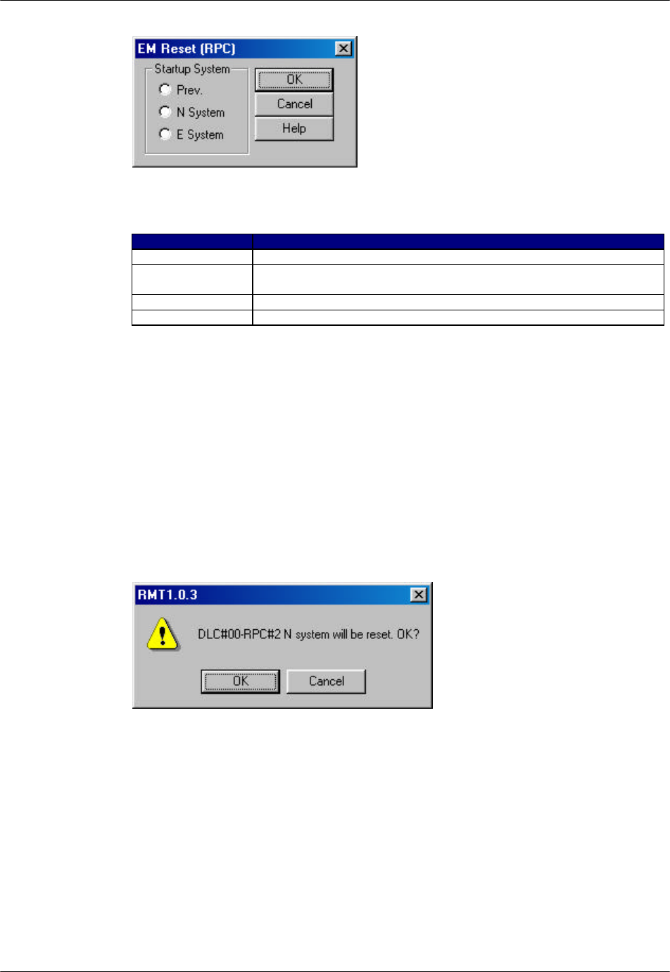
4. If an RPC needs to be reset, select the RPC and click OK. This brings up the
EM Reset (RPC) window as shown in the figure below.
RPC/RP Configuration RPC/RP Manual
WLL-RPC/RP-IN/UM-1.0 19June2000
4-
66
Figure 4-67: EM Reset (RPC) Window
Field Name Description
Startup System Determine which SDM to use for operating RPC after resetting.
Prev. Previous ACT SDM. After resetting, RPC starts up and runs based on
the previous ACT SDM.
N System SDM-#N. After resetting, RPC starts up and runs based on SDM-#N.
E System SDM-#E. After resetting, RPC starts up and runs based on SDM-#E.
Table 4-16: EM Reset (RPC) Window Field Description
F NOTE: Refer to Section 4.3 for detailed description of the N and E systems.
5. There are three options in the Startup System block. Select the system to
start with and click OK.
6. A confirmation window appears, as displayed in the figure below. Click OK
to reset the RPC or Cancel to stop the transaction.
Figure 4-68: Reset Confirmation Window
7. After EM reset is complete, the PC will disconnect from the RPC. To resume
normal operations, reconnect to the RPC.
8. Click the RPC Status button to open the RPC Status View window to verify
that the component is in operation.
RPC/RP Manual RPC/RP Configuration
19June2000 WLL-RPC/RP-IN/UM-1.0
4-
67
4.6 RPC Statistics
The function of RPC statistics can generate an RPC traffic report that displays the
traffic status for either the entire period and all the RPCs and RPs, or the specific
period and an individual RPC or RP. This is a useful feature for analyzing the
RPC traffic. In addition, the RPC statistics can also create the RP status report.
4.6.1 RPC Traffic Report
1. To generate the RPC/RP traffic report, click the Statistics main menu on the
Client View window and select RPC Statistics Report. The criteria setting
window opens, as shown in the figure below.
Figure 4-69: Criteria Setting Window
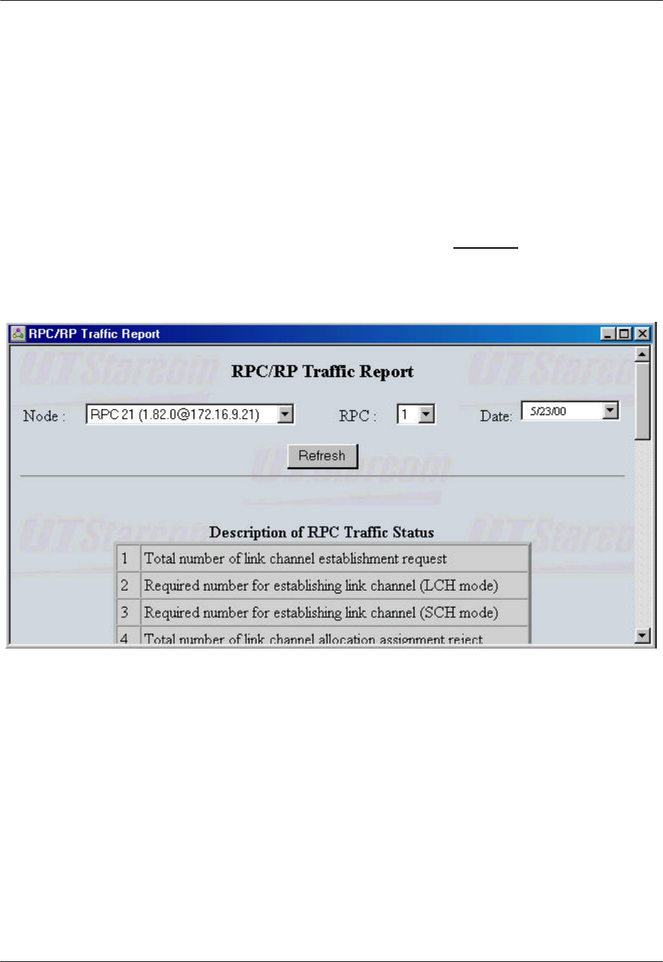
2. Select the criteria for the RPC traffic data to be retrieved and click the Refresh
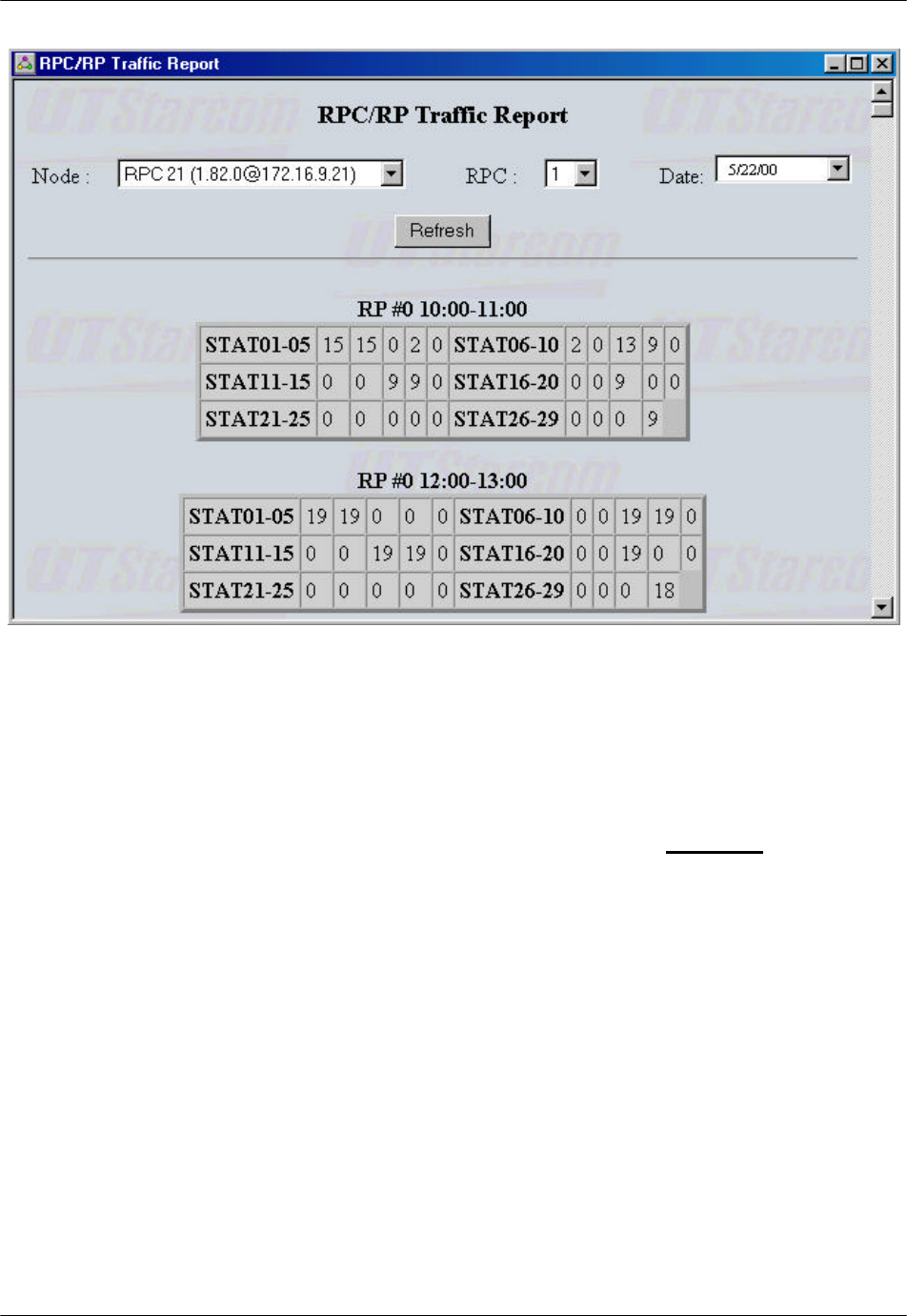
button. After a few seconds the RPC/RP Traffic Report appears on the
screen, as illustrated in the figure below.
RPC/RP Configuration RPC/RP Manual
WLL-RPC/RP-IN/UM-1.0 19June2000
4-
68
Figure 4-70: RPC/RP Traffic Report Window
F NOTE: Sometimes nothing happens after the Refresh button is clicked. The
reason is that the RPC board may have been reset by RTs and there is no
synchronization between the RPC device manager and the RPC board. In that
case go to the RPC System View window, click open the Configure main menu,
and select Set Time. The Set Time window opens. Click OK to synchronize the
RPC device manager with the RPC board. After the traffic data pile up in the
board the RPC device manager can retrieve the traffic report. This rule also
applies to the RP Status Report operation, as described in Section 4.6.3.
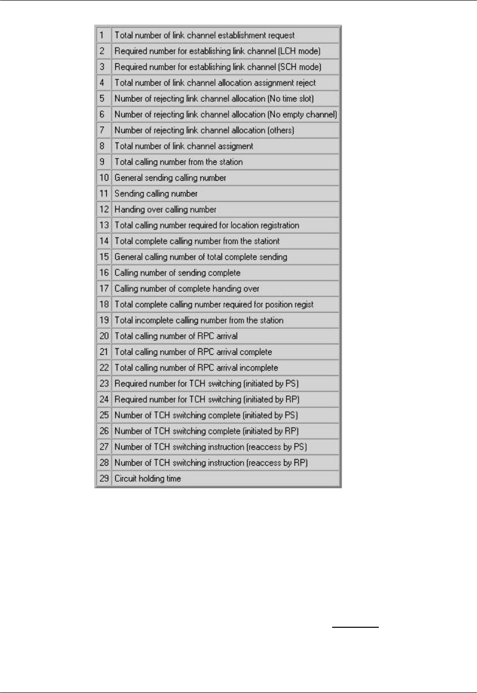
3. Figure 4-70 presents the traffic report for each of the 32 associated RPs. The
report is organized in such a way that each block displays all the 29 traffic
statistics elements for an RP for the period of one hour. Refer to the following
figure for the description of each of the 29 statistics elements.
RPC/RP Manual RPC/RP Configuration
19June2000 WLL-RPC/RP-IN/UM-1.0
4-
69
Figure 4-71: Description of RPC Traffic Status
4.6.2 RPC Outstanding Alarms
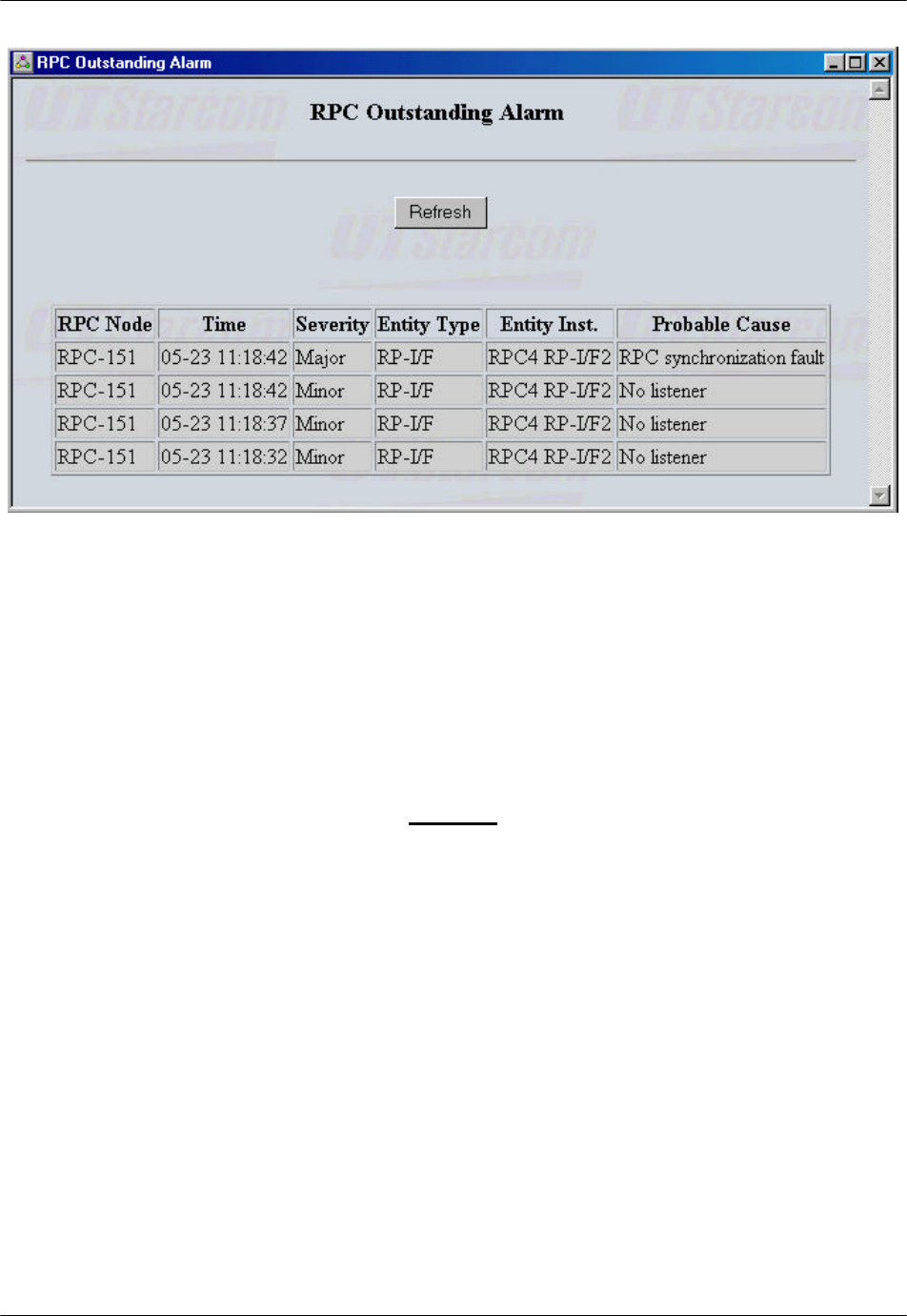
RPC Outstanding Alarms list all the alarms for each RPC which haven’t been
fixed.
1. To display the RPC outstanding alarms, click the Statistics main menu on the
Client View window and select the RPC Outstanding Alarms option. This
brings up the RPC Outstanding Alarm window, as shown in Figure 4-72.
RPC/RP Configuration RPC/RP Manual
WLL-RPC/RP-IN/UM-1.0 19June2000
4-
70
Figure 4-72: RPC Outstanding Alarm Window
2. Click the Refresh button to retrieve the current outstanding alarms.
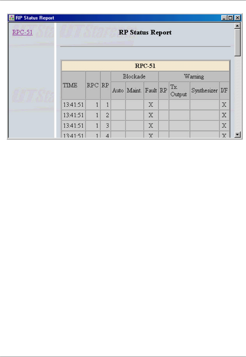
4.6.3 RP Status Report
This feature displays the blockade and warning statuses for all the 32 RPs of the
selected RPC.
1. To view the report, click the Statistics main menu and select the RP Status
Report option on the Client View window. The RP Status Report page opens
on the Main View window, as shown below.
RPC/RP Manual RPC/RP Configuration
19June2000 WLL-RPC/RP-IN/UM-1.0
4-
71
Figure 4-73: RP Status Report Page
2. Select the target RPC on the left frame to bring up the status report for the
associated RPs.

RPC/RP Configuration RPC/RP Manual
WLL-RPC/RP-IN/UM-1.0 19June2000
4-
72

19June2000 WLL-RPC/RP-IN/UM-1.0
A
Specifications
A Specifications
A.1 RPC Specifications
Item Specifications
Functions Control and power feeding to RPs
Concentration of speech path
Conversion of protocol
Capacity
Max. number of controlled subscribers 960
Max. number of controlled RPs 32
Max. number of COT interfaces 4
Max. speech paths 120
COT Interface
Physical Interface E1 interface (30B+D)
2.048 Mbit/s (B: 64 kbit/s D: 64 kbit/s)
TE mode
ITU-T Rec. G.703, G.704
Speech coding rule A-law
Logical Interface Non-facility associated signaling
Q.931
RP Interface
Physical Interface Proprietary (4B+D+K)
192 kbit/s
(B: 32 kbit/s D: 16 kbit/s K: 8 kbit/s)
Speech coding rule ADPCM
Line power feeding voltage 112-116 V DC
Logical Interface Layer 2: TTC Rec. JT-Q921-b
Layer 3: Proprietary
Power Condition
Input voltage 42-58 V DC
Max. input current Approx. 7.5 A
Operational Environment
Temperature -10° - +50° C
Humidity Less than 95% (non-condensing)
Dimensions 640mm (H) x 494mm (W) x 210mm (D)
Table A-1: RPC Specifications
Specifications RPC/RP Manual
WLL-RPC/RP-IN/UM-1.0 19June2000
A-2
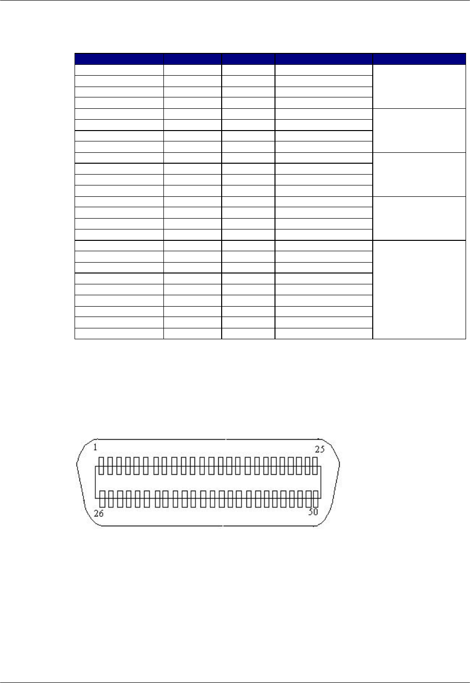
A.1.1 Champ Connector Pin Assignments
Assignment Pin # Pin # Assignment Remarks
RP # 1 (L1) 1 26 RP # 1 (L2)
RP # 2 (L1) 2 27 RP # 2 (L2)
RP # 3 (L1) 3 28 RP # 3 (L2)
RP # 4 (L1) 4 29 RP # 4 (L2)
RPIF Card #1
RP # 5 (L1) 5 30 RP # 5 (L2)
RP # 6 (L1) 6 31 RP # 6 (L2)
RP # 7 (L1) 7 32 RP # 7 (L2)
RP # 8 (L1) 8 33 RP # 8 (L2)
RPIF Card #2
RP # 9 (L1) 9 34 RP # 9 (L2)
RP# 10 (L1) 10 35 RP # 10 (L2)
RP# 11 (L1) 11 36 RP # 11 (L2)
RP# 12 (L1) 12 37 RP # 12 (L2)
RPIF Card #3
RP# 13 (L1) 13 38 RP # 13 (L2)
RP# 14 (L1) 14 39 RP # 14 (L2)
RP# 15 (L1) 15 40 RP # 15 (L2)
RP# 16 (L1) 16 41 RP # 16 (L2)
RPIF Card #4
Not in use 17 42 Not in use
Not in use 18 43 Not in use
Not in use 19 44 Not in use
Not in use 20 45 Not in use
Not in use 21 46 Not in use
Not in use 22 47 Not in use
Not in use 23 48 Not in use
Not in use 24 49 Not in use
Not in use 25 50 Not in use
No need to attach
Table A-2: Champ Connector 1-Pin Assignments
The Pin numbers are marked on the Champ connector. This chart applies to J16
on the motherboard in the RPC. RP has no polarity.
Figure A-1: Champ Connector Contact Face View

RPC/RP Manual Specifications
19June2000 WLL-RPC/RP-IN/UM-1.0
A-3
Assignment Pin # Pin # Assignment Remarks
RP # 17 (L1) 1 26 RP # 17 (L2)
RP # 18 (L1) 2 27 RP # 18 (L2)
RP # 19(L1) 3 28 RP # 19 (L2)
RP # 20(L1) 4 29 RP # 20 (L2)
RPIF Card #5
RP # 21(L1) 5 30 RP # 21 (L2)
RP # 22(L1) 6 31 RP # 22 (L2)
RP # 23(L1) 7 32 RP # 23 (L2)
RP # 24(L1) 8 33 RP # 24 (L2)
RPIF Card #6
RP # 25(L1) 9 34 RP # 25 (L2)
RP# 26 (L1) 10 35 RP # 26 (L2)
RP# 27(L1) 11 36 RP # 27 (L2)
RP# 28(L1) 12 37 RP # 28 (L2)
RPIF Card #7
RP# 29(L1) 13 38 RP # 29 (L2)
RP# 30(L1) 14 39 RP # 30 (L2)
RP# 31(L1) 15 40 RP # 31 (L2)
RP# 32(L1) 16 41 RP # 32 (L2)
RPIF Card #8
Not in use 17 42 Not in use
Not in use 18 43 Not in use
Not in use 19 44 Not in use
Not in use 20 45 Not in use
Not in use 21 46 Not in use
Not in use 22 47 Not in use
Not in use 23 48 Not in use
Not in use 24 49 Not in use
Not in use 25 50 Not in use
No need to attach
Table A-3: Champ Connector 2 - Pin Assignment
Pin numbers are marked on the Champ connector. This chart applies to J17 on
the motherboard in the RPC. RP has no polarity.
Figure A-2: Champ Connector Contact Face View
Specifications RPC/RP Manual
WLL-RPC/RP-IN/UM-1.0 19June2000
A-4
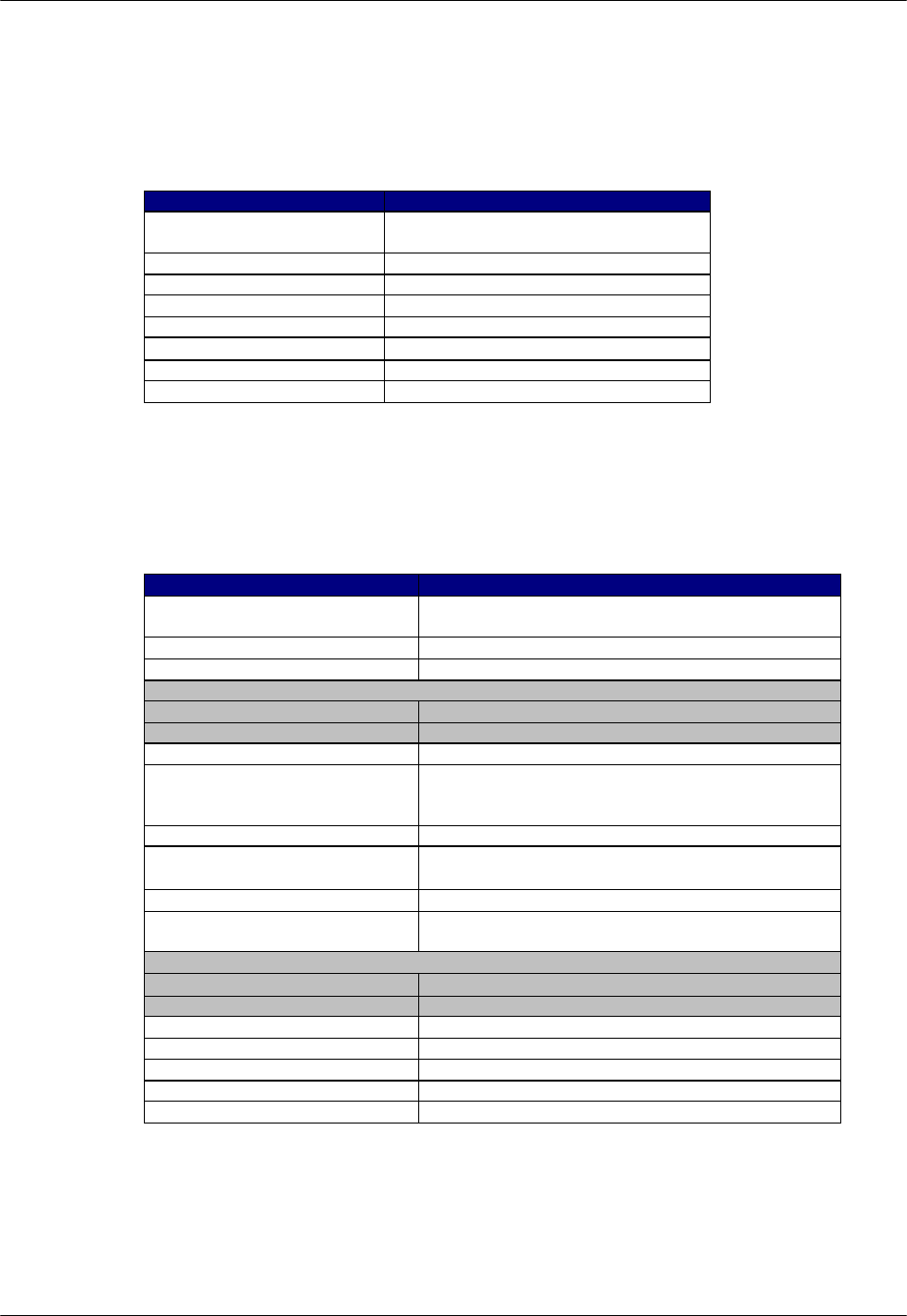
A.2 RP Specifications
A.2.1 Radio Features
Item Contents
Radio frequency For private use: 1,895-1,906.1 MHz
For public use: 1,895-1,910 MHz
Carrier spacing 300 KHz
Output power 10 mW
Radio access TDMA-TDD
Number of TDMA slots 4 (for full rate CODEC)
Modulation π/4 shift QPSK (roll-off factor = 0.5)
Transmission bit rate 384 kbps
Speech coding 32 kbps ADPCM
Table A-4: Radio Features
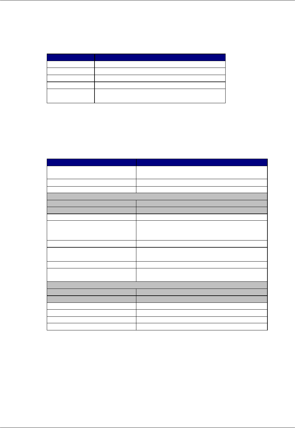
A.2.2 Outdoor Type RP
Item Specifications
RF output power average
(Peak) 10 mW
(80 mW)
Sensitivity (Static BER = 1%) 14 dB µV
Antenna (Diversity) 2 external antennae (2 branch)
Diversity
RX (uplink) Antenna selection diversity (frame by frame)
TX (downlink) Transmitter antenna selection diversity (2 branch)
Air interface Based on RCR STD-28 ver.2
RPC interface Proprietary
BRI equivalent
(4B+D+K) x 1
Speech coding rate 32 kbps (ADPCM) x 3 or 4
Maximum wire line length (⇔
RPC)
3.5 km (φ 0.4)
5.0 km (φ 0.5)
Maximum power consumption Approx. 3 W
Power source Line power feeding (phantom) from RPC
56 - 116 V DC
Operational Environment
Temperature -10° to + 50°C
Humidity Less than 95 % (non-condensing)
Size 260 x 215 x 100 mm
Weight Approx. 2 kg
Line connection Screw less terminal
Antenna connection TNC connector
Battery backup None
Table A-5: Outdoor RP Specifications
RPC/RP Manual Specifications
19June2000 WLL-RPC/RP-IN/UM-1.0
A-5
A.2.2.1 Antenna
The recommended antenna specifications for the outdoor type RP are shown in
Table A-6.
Items: Recommended Specifications
Type Co-Liner antenna (Omni-directional) 2 branch
Gain 7dBi
Impedance 50Ω
VSWR less than 1.5
Cable Length: within 1m
Attenuation: 0.5dB/m
Table A-6: Antenna Specifications - Outdoor Type RP
A.2.3 Indoor Type RP
Item Specifications
RF output power average
(Peak) 10 mW
(80 mW)
Sensitivity (Static BER = 1%) 14 dB µV
Antenna (Diversity) Built-in antenna (2 branch 2.4 dBi)
Diversity
RX (uplink) Antenna selection diversity (frame by frame)
TX (downlink) Transmitter antenna selection diversity (2 branch)
Air interface Based on RCR STD-28 ver.2
RPC interface Proprietary
BRI equivalent
(4B+D+K) x 1
Speech cording rate 32 kbps (ADPCM) x 3 or 4
Maximum wire line length (⇔
RPC) km (φ 0.4)
5.0 km (φ 0.5)
Maximum power consumption Approx. 3 W
Power source Line power feeding (phantom) from RPC
56 - 116 V DC
Operational Environment
Temperature 0° C to +50° C
Humidity Less than 95 % (non-condensing)
Size 154(H) x 142(W) x 47(D) mm
Weight Approx. 0.6 kg
Line connection Modular connector
Battery backup None
Table A-7: Indoor RP Specifications

Specifications RPC/RP Manual
WLL-RPC/RP-IN/UM-1.0 19June2000
A-6

19June2000 WLL-RPC/RP-IN/UM-1.0
B
Glossary
B Glossary
ADPCM Adaptive Differential Pulse Code Modulation
BRI Basic Rate Interface
CNT Control Module
COT Central Office Terminal
CPU Central Processing Unit
CRC Cyclic Redundancy Check
E1IF E1 Interface
ECNT Enhanced Control Module
FIFO First In - First Out
HDLC High speed Digital Loop Carrier
HDSL High speed Digital Subscriber Loop
ISDN Integrated Services Digital Network
ITU International Telecommunications Union
LE Local Exchange
LED Light Emitting Diode
LIF Line Interface
OA&M Operations, Administration and Maintenance
PC Personal Computer

Glossary RPC/RP Manual
WLL-RPC/RP-IN/UM-1.0 19June2000
B-
2
PCM Pulse Code Modulation
PHS Personal Handyphone System
RAM Random Access Memory
ROM Read Only Memory
RP Radio Port
RPC Radio Port Controller
RPIF Radio Port Interface
TIF Trunk Interface

RPC/RP Manual Glossary
19June2000 WLL-RPC/RP-IN/UM-1.0
B-
3

19June2000 WLL-RPC/RP-IN/UM-1.0
C
Editor’s Note
C Editor’s Note
C.1 Notice to Customers
UTStarcom reserves the right to change the specifications and materials contained
herein without notice, and shall not be responsible for any damages caused by
reliance on the material as presented, including, but not limited to, typographical,
arithmetic, and listing errors.
Trademarks
All trademarks and service marks used in this document belong to their respective
owners.
Warranty and Return Policy
Refer to the terms and conditions of the contract for warranty and return policy
details.
Customer Service
Refer to the terms and conditions of the contract for customer service policy
details, or call the local UTStarcom Facility. Contact UTStarcom’s US
headquarters if you can’t find your local UTStarcom facility in the list below.
U.S. Facilities and Operations
UTStarcom, Inc.
1275 Harbor Bay Parkway, Suite 100
Alameda, CA 94502, USA
Tel. 1-510-864-8800
Fax 1-510-864-8802
UTStarcom New Jersey R&D Center
33 Wood Avenue South 8th floor
Iselin, NJ 08830, USA
Tel. 1-732-767-5200
Fax 1-732-548-1099
China Facilities and Operations

Editor’s Note RPC/RP Manual
WLL-RPC/RP-IN/UM-1.0 19June2000
C-
2
UTStarcom (China) Ltd.
CNT Manhattan Building, 11th Floor
6 Chao Yang Men Bei Da Jie
Dong Cheng District, Beijing, 100027
P.R. China
Tel. 86-10-6554-2030
Fax 86-10- 6554-2058
Zhejiang Unitel Telecommunications
Equipment Ltd
3 Yile Industrial Park 3/4F Building
129 Wen Yi Rd.
Hangzhou, 310012, P.R. China
Tel. 86-571-886-2341
Fax 86-571-886-2349
UTStarcom, Shanghai Office
Rm 1901-1902
227 Huang Pi North Road
Shanghai, 200237, P.R. China
Tel. 86-21-637-58766
Fax 86-21-637-58755
Guangdong UTStarcom Co. Ltd.
4 Yunshan Road East, North River
Huizhou, Guangdong 516001, P.R. China
Tel. 86-752-280-8868
or 86-752-280-8818
Fax 86-20-280-8838
UTS Guangzhou Subsidiary
10F GuangZhou Gold Lion Tower
138 Tiyu Road East
Guangzhou, 510620, P.R. China
Tel. 86-20-3878-0263
Fax 86-20-3880-7411
UTStarcom (Hangzhou) Ltd.
3 Yile Industrial Park 3/4F Building
129 Wenyi Rd.
Hangzhou, 310012, P.R. China
Tel. 86-571-886-2341
Fax 86-571-886-2349
International Facilities and Operations
UTStarcom, Singapore Office
ACTEL Communications
141 Middle Road #06-02
GSM Building, Singapore 188976
Tel. 65-334-6602
Fax 65-334-6606
UTStarcom, India Office
W.S. Telesystems Limited
Dr. Brownamma Towers
11 Floor, 70/1, Mission Road
Bangalore - 560 027, India
Tel. 91-80-227-4444
Fax 91-80-222-5268
UTStarcom, Thailand Office
For Your Infosys Co., Ltd
47/15 Soi Lardprao 122
Bangkapi Bangkok 10310, Thailand
Tel. 66-2-539-7140
or 66-2-934-0179 ext 80
Fax 66-2-539-7431
UTStarcom, Philippines Office
Rocis, Inc.
GF-A Cordova Condominium Building
Valero cor. Sedeño Sts.
Salcedo Village, Makati, Metro Manila,
Philippines 1227
Tel. 63-2-818-9783
Fax 63-2-815-2727

RPC/RP Manual Editor’s Note
19June2000 WLL-RPC/RP-IN/UM-1.0
C-
3
C.2 How to Comment on This Document
UTStarcom strives to continuously improve its products and services to better
help our customers succeed. As our valued customer, you can help us by giving
us your comments on this manual. A feedback form is located on the next page.
Please take a few minutes to complete the form and send it to the following
address by mail or fax. If you have any comments and suggestions, please send
them to this address, too. Your valuable feedback is highly appreciated.
Wireless Product Manager
UTStarcom Inc.
33 Wood Avenue South, 8th floor
Iselin, New Jersey 08830
USA
Fax: 732-548-1099 Web Site: http://www.utstar.com
Email: wireless_prod_mgr@utstar.com

Editor’s Note RPC/RP Manual
WLL-RPC/RP-IN/UM-1.0 19June2000
C-
4

RPC/RP Manual Editor’s Note
19June2000 WLL-RPC/RP-IN/UM-1.0
C-
5
C.3 Feedback Form
Organization of this manual:
r extremely poor r poor r moderate r good r excellent
Clarity of this manual:
r extremely poor r poor r moderate r good r excellent
Level of detail of this manual:
r not enough r just right r too much
Level of technical description:
r too superficial r just right r hard to understand
Suggested improvements and topics you want to see covered in future releases:
Errors found (attach additional sheets if necessary):
Page # Description

Editor’s Note RPC/RP Manual
WLL-RPC/RP-IN/UM-1.0 19June2000
C-
6
Please tell us about yourself:
Company
Title / Job Responsibility
Years of Experience
In case we contact you, please provide the following (optional):
Your Name
Phone Number
E-mail Address
------------------- fold along line -----------------------------------------------------------------------------------------------------
tape here
------------------- fold along line -----------------------------------------------------------------------------------------------------
Post Office
will not
deliver
without
stamp
Wireless Product Manager
UTStarcom
33 Wood Avenue South, 8th floor
ISELIN, NJ 08830
USA

RPC/RP Manual Editor’s Note
19June2000 WLL-RPC/RP-IN/UM-1.0
C-
7