UTStarcom Korea Technologies UTS-EA7H75B Wireless Local Loop Fixed Terminal User Manual Cover
UTStarcom Korea Technologies Ltd. Wireless Local Loop Fixed Terminal Cover
Contents
Manual 3
RP Installation RPC/RP Manual
WLL-RPC/RP-IN/UM-1.0 19June2000
3-
14
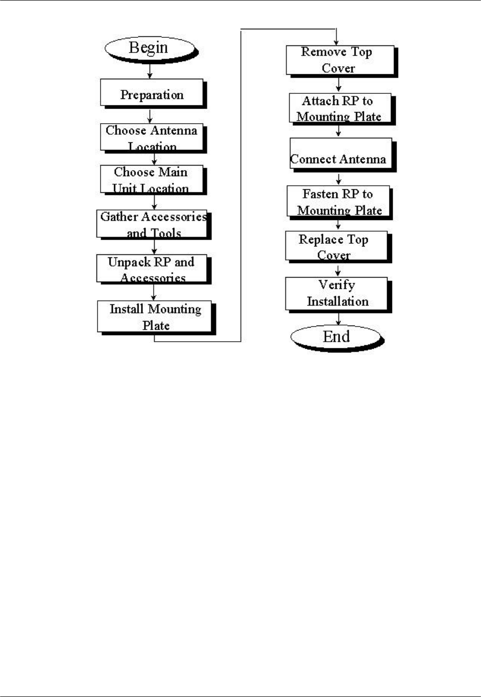
Figure 3-12: Outdoor RP Instruction Flow Chart
3.4.1 Before Beginning
To ensure that the outdoor RP installation goes smoothly, it is necessary to make
adequate planning prior to the installation, including:
• Tools required
• Number of people needed to complete the installation
• Location of the RP Main Unit
3.4.2 Outdoor RP Installation
Follow the steps below to install an outdoor RP:
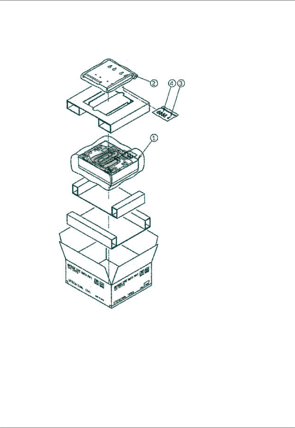
1. Unpack the outdoor RP and accessories and make sure they are in good
condition. Refer to Figure 3-13. The package includes:
• Outdoor RP (1)
RPC/RP Manual RP Installation
19June2000 WLL-RPC/RP-IN/UM-1.0
3-
15
• Mounting plate (2)
• One M4 screw (3)
• Four M6 screws (4)
Figure 3-13: Overview of the RP, Packing, and Accessories
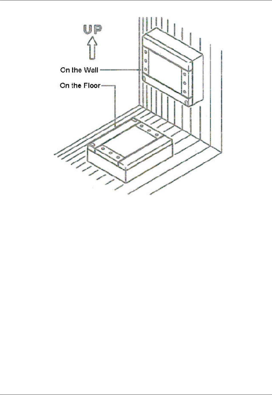
2. Make sure that the outdoor RP is installed in one of the positions shown in
Figure 3-14.
RP Installation RPC/RP Manual
WLL-RPC/RP-IN/UM-1.0 19June2000
3-
16
Figure 3-14: Outdoor RP Recommended Positions
F WARNING: Installation of the RP in any other position may permit moisture to
enter the device possibly causing damage or injury.
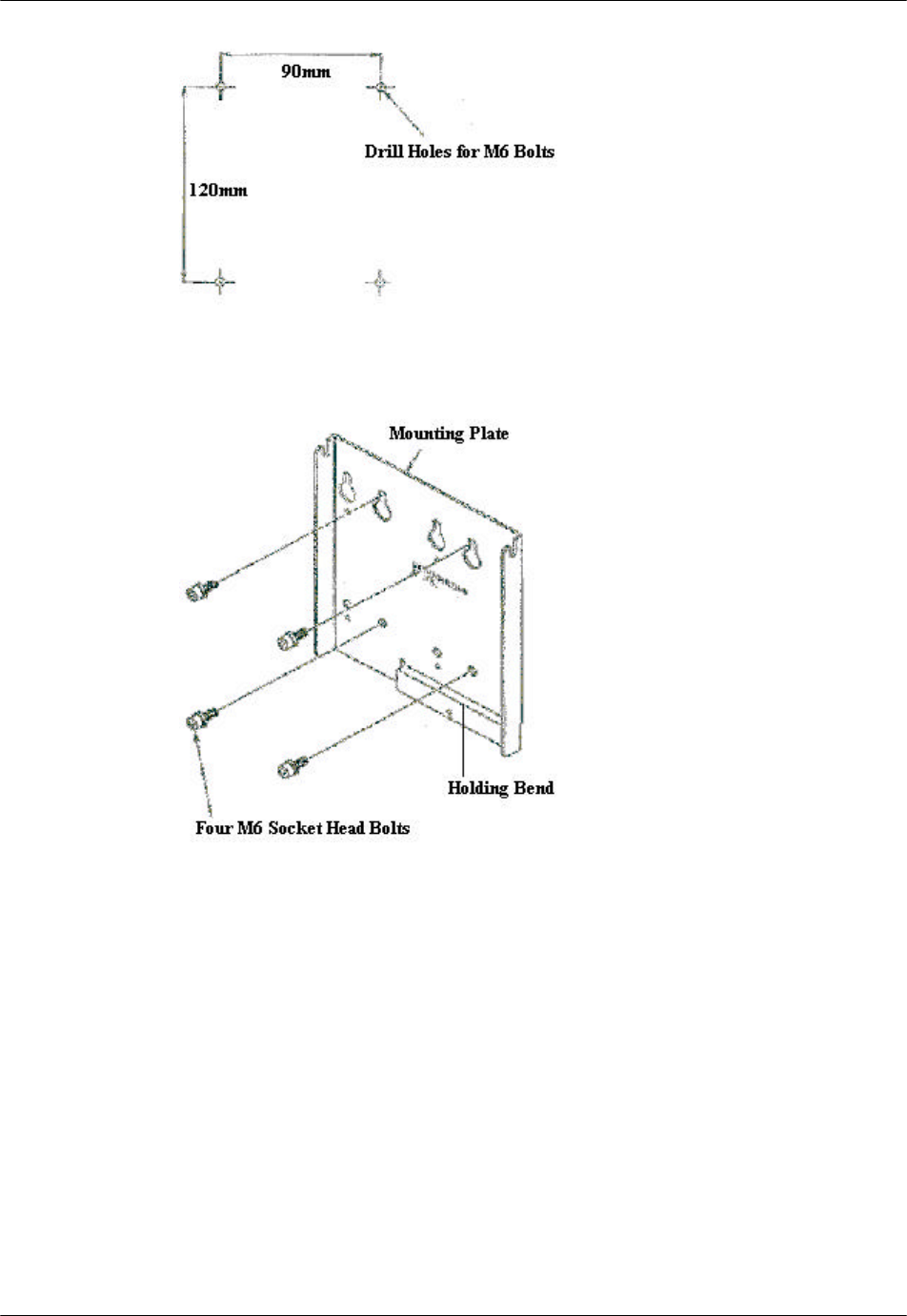
3. Pre-drill holes for bolts according to the dimensions shown in Figure 3-15.
Attach the mounting plate to a wall with 4 bolts. Notice that the lower right
edge of the mounting plate has a bend in it. The purpose of this bend is to
hold the antenna connectors in place. Refer to Figure 3-15.
RPC/RP Manual RP Installation
19June2000 WLL-RPC/RP-IN/UM-1.0
3-
17
Figure 3-15: Mounting Plate
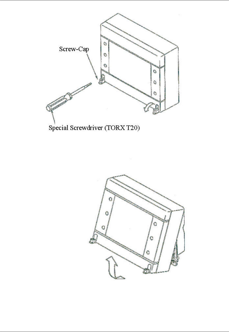
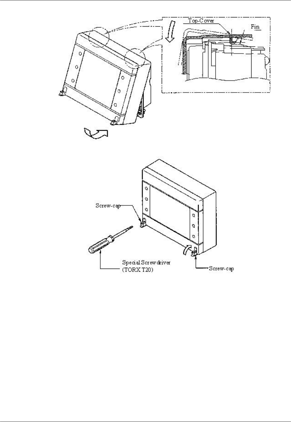
4. To remove the top cover, lower the screw caps and loosen the screws with the
special screwdriver. Pull the top cover backward and upward from the main
unit as shown in Figure 3-16.
RP Installation RPC/RP Manual
WLL-RPC/RP-IN/UM-1.0 19June2000
3-
18
Figure 3-16: Top Cover Removal
RPC/RP Manual RP Installation
19June2000 WLL-RPC/RP-IN/UM-1.0
3-
19
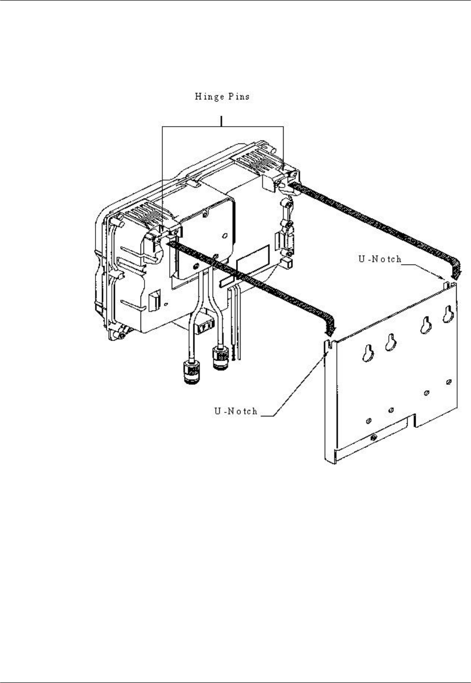
5. Mount main unit on the mounting plate. Position both the hinge pins in the u-
notches on the mounting plate. Refer to Figure 3-17. Do not fasten with the
screws right now. The antenna cables must be connected first.
Figure 3-17: Mount Main Unit
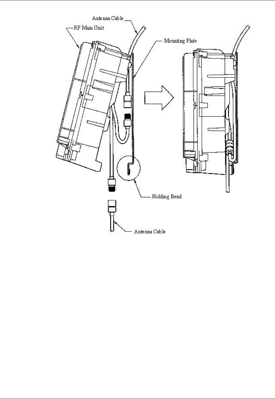
6. Connect each antenna cable and push the antenna connectors and surplus
antenna cable in between the mounting plate and the RP main unit. Make sure
that the antenna connectors are above the holding bend of the mounting plate
and that the antenna cables are not caught by it.
RP Installation RPC/RP Manual
WLL-RPC/RP-IN/UM-1.0 19June2000
3-
20
Figure 3-18: Antenna Cable Connections
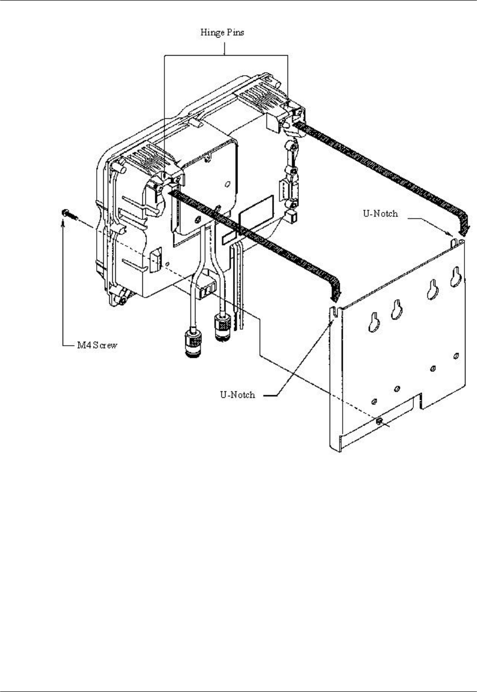
7. Affix main unit to the mounting plate with the M4 screw as shown in Figure
3-19.
RPC/RP Manual RP Installation
19June2000 WLL-RPC/RP-IN/UM-1.0
3-
21
Figure 3-19: RP Attachment to the Mounting Plate
8. Replace the top cover. Make sure it is properly positioned over the fin on the
main unit as shown in Figure 3-20. Tighten the screws in the top cover and
replace the screw caps.
RP Installation RPC/RP Manual
WLL-RPC/RP-IN/UM-1.0 19June2000
3-
22
Figure 3-20: Top Cover Attachment
9. This completes the installation of the outdoor RP.

RPC/RP Manual RP Installation
19June2000 WLL-RPC/RP-IN/UM-1.0
3-
23
19June2000 WLL-RPC/RP-IN/UM-1.0
4
RPC/RP
Configuration
4 RPC/RP Configuration
After the installation of the RPC and RP, configuration must be made to provision
the RPC and RP. This is done through the Netman network management system.
Netman is the network management tool for the system. It centralizes the
management of all the DMs in the network, including the RPCs. This chapter
describes the RPC/RP configuration process through Netman 2000.
4.1 Initialize an RPC Node
RPCs are represented as independent DMs on the Netman Main View window
although they are actually controlled by the COT node to which they are attached.
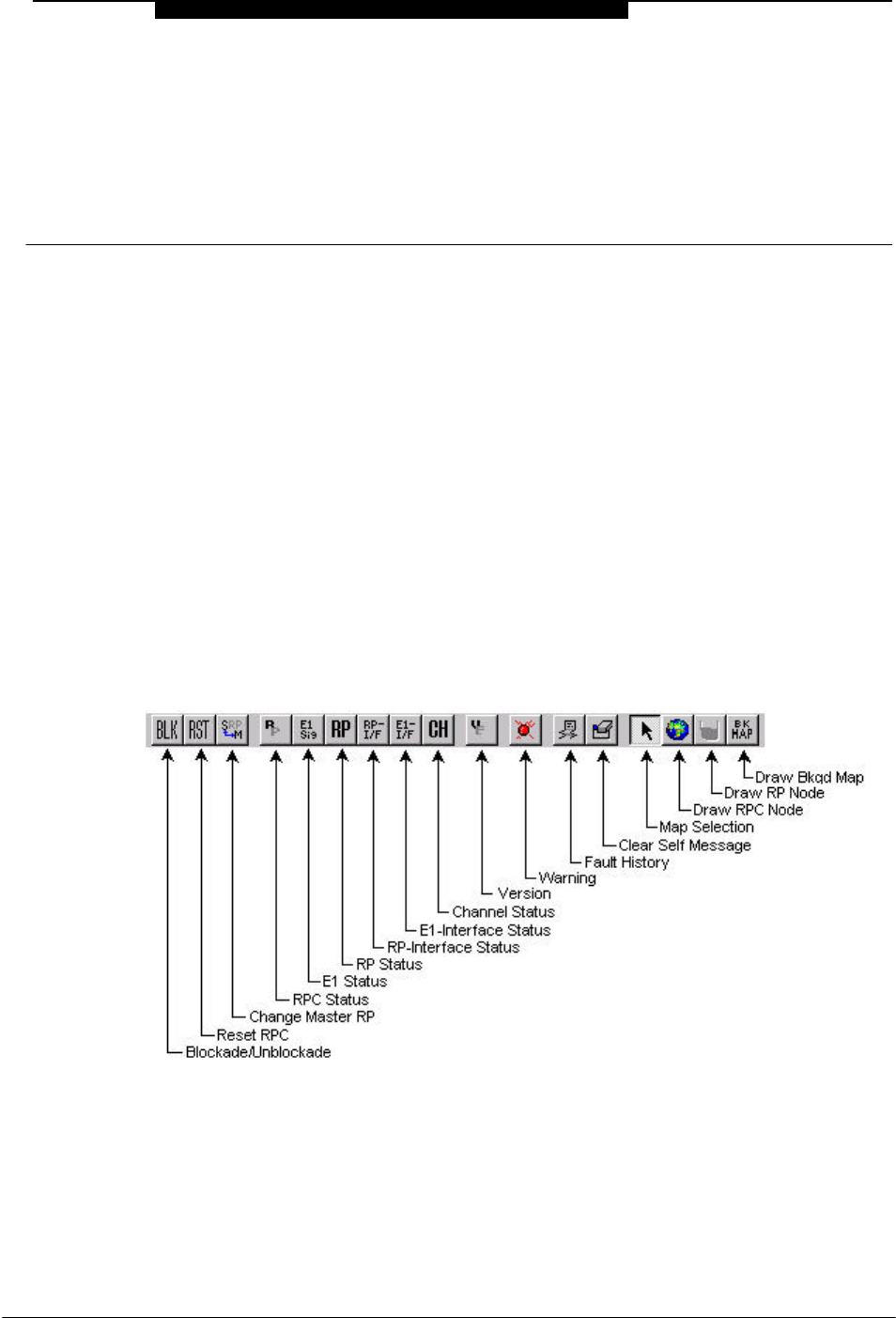
Figure 4-1 and Figure 4-2 represent the toolbar and pull-down menu of the RPC
DM window.
Figure 4-1: Toolbar and Description (RPC R2.4)
RPC/RP Configuration RPC/RP Manual
WLL-RPC/RP-IN/UM-1.0 19June2000
4-
2
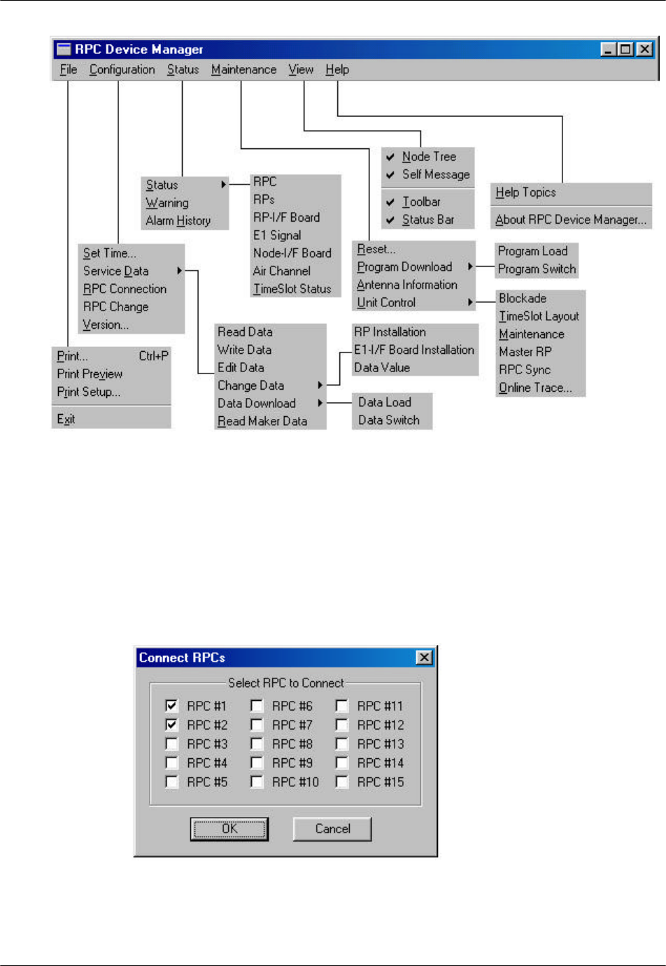
Figure 4-2: Netman Pull-down Menus (RPC R2.4)
This section describes the procedures to initialize an RPC node. Follow the steps
below to get connected to an RPC:
1. On the Main View window of the Netman network management system,
double click the target RPC icon. This opens the Connect RPCs window, as
shown below.
Figure 4-3: Connect RPCs Window
RPC/RP Manual RPC/RP Configuration
19June2000 WLL-RPC/RP-IN/UM-1.0
4-
3
2. There are 15 RPCs to select from. Click the check boxes of the RPCs to be
connected and then click OK.
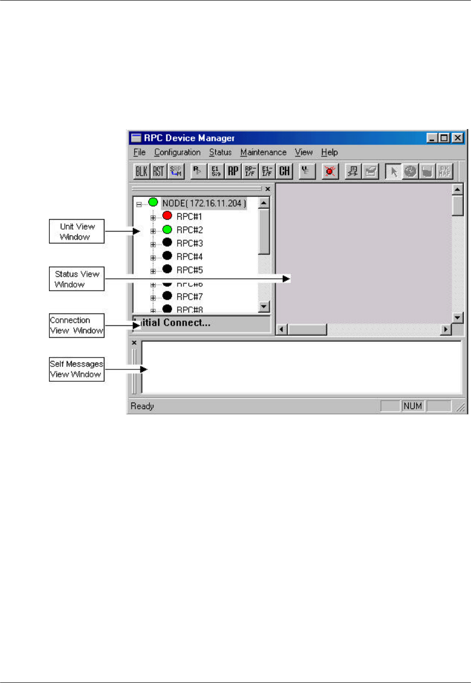
3. A connection status box appears, displaying the connection process. When
the process is complete, the RPC window opens with four frames, as
displayed in Figure 4-4.
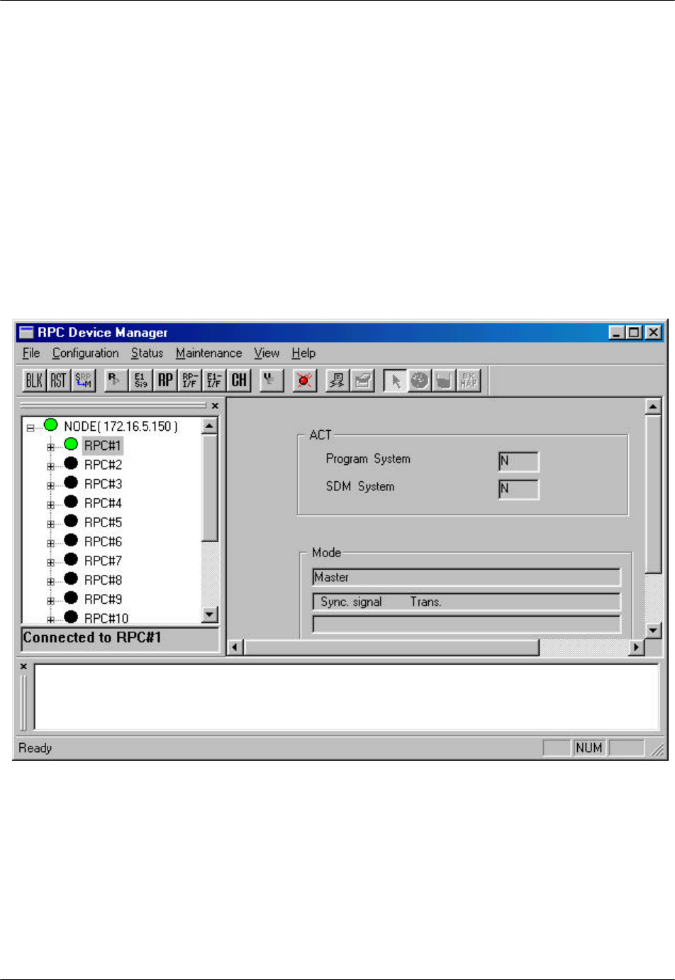
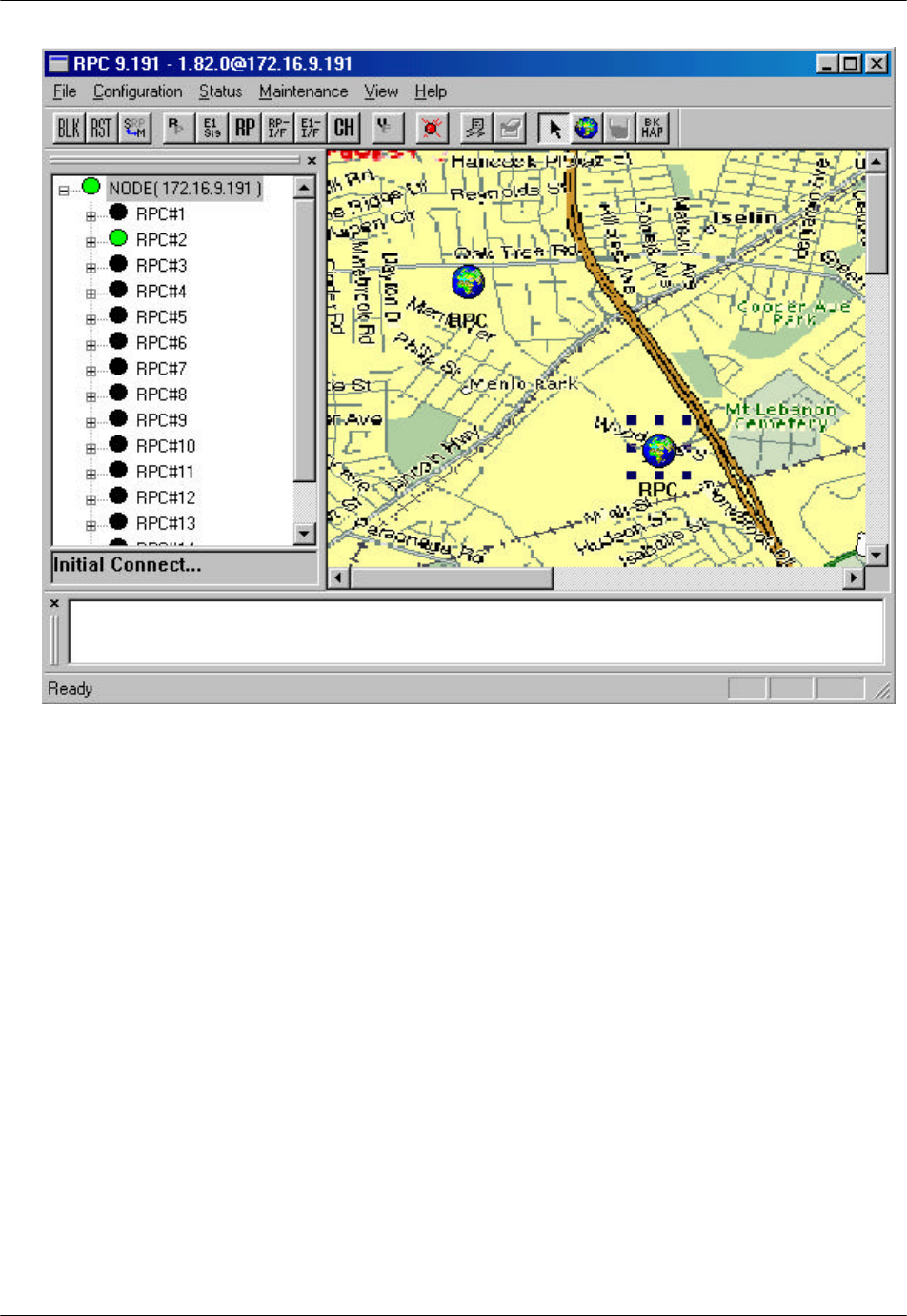
Figure 4-4: RPC Window
The top left frame is called the Unit View window. It lists the current units,
such as, RPCs, RPs, interfaces, etc. The NODE displays its IP address. The
connection status of the RPC nodes on the tree structure is represented in three
different colors. The green and red color indicate connected and unconnected
RPCs respectively, whereas the RPC nodes in black color indicate that they
are not selected for connection.
The top right frame is called the Status View window. It displays the relevant
status information corresponding to the selection on the left, on the menu bar,
or on the toolbar.
The small frame under the Unit View window is the Connection View
window. It displays the connection status and the connected RPC.
RPC/RP Configuration RPC/RP Manual
WLL-RPC/RP-IN/UM-1.0 19June2000
4-
4
Finally, the frame at the bottom is the Self Messages window. It displays
messages about the command execution results, trap messages, or warnings, if
there is any.
4. To get connected to a certain RPC, reselect the RPC by clicking the RPC on
the Unit View window. A connection status box appears, displaying the
connection process. If the connection is successful, a message will appear on
the Connection View window, stating “Connected to RPC#…” If the
connection fails, the message will be: “Not Connected!”
5. When the connection is complete, the Status View window displays the
relevant status information about the RPC or other units under it, depending
on which unit is selected. The figure below illustrates an RPC window.
Figure 4-5: RPC Window
6. Open an RPC by clicking the + sign to the left of the RPC. This displays the
RPs, RP Interface Borad, E1 Signal, Node Interface Board, and Air Channel
inside. Users may access each of the RPs by clicking the + sign to the left of
the RPs. Each RPC controls 32 RPs.
RPC/RP Manual RPC/RP Configuration
19June2000 WLL-RPC/RP-IN/UM-1.0
4-
5
4.1.1 Background Map
A street map can be added as a background image on the Status View window to
highlight the location of the RPC or RP.
1. Click NODE on the Unit View window to enable the Draw Background Map
button on the RPC window.
2. Click the Draw Background Map button and click anywhere on the Status
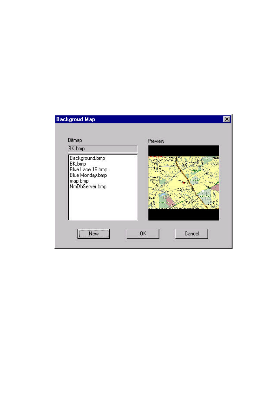
View window. The Background Map window opens, as shown in Figure
4-6.
Figure 4-6: Background Map Window
3. Select the target background file from the Bitmap field. The Preview field
displays the selected background image. If users are satisfied with the image,
click OK. The image is pasted to the background of the Status View window,
as illustrated in Figure 4-7.
RPC/RP Configuration RPC/RP Manual
WLL-RPC/RP-IN/UM-1.0 19June2000
4-
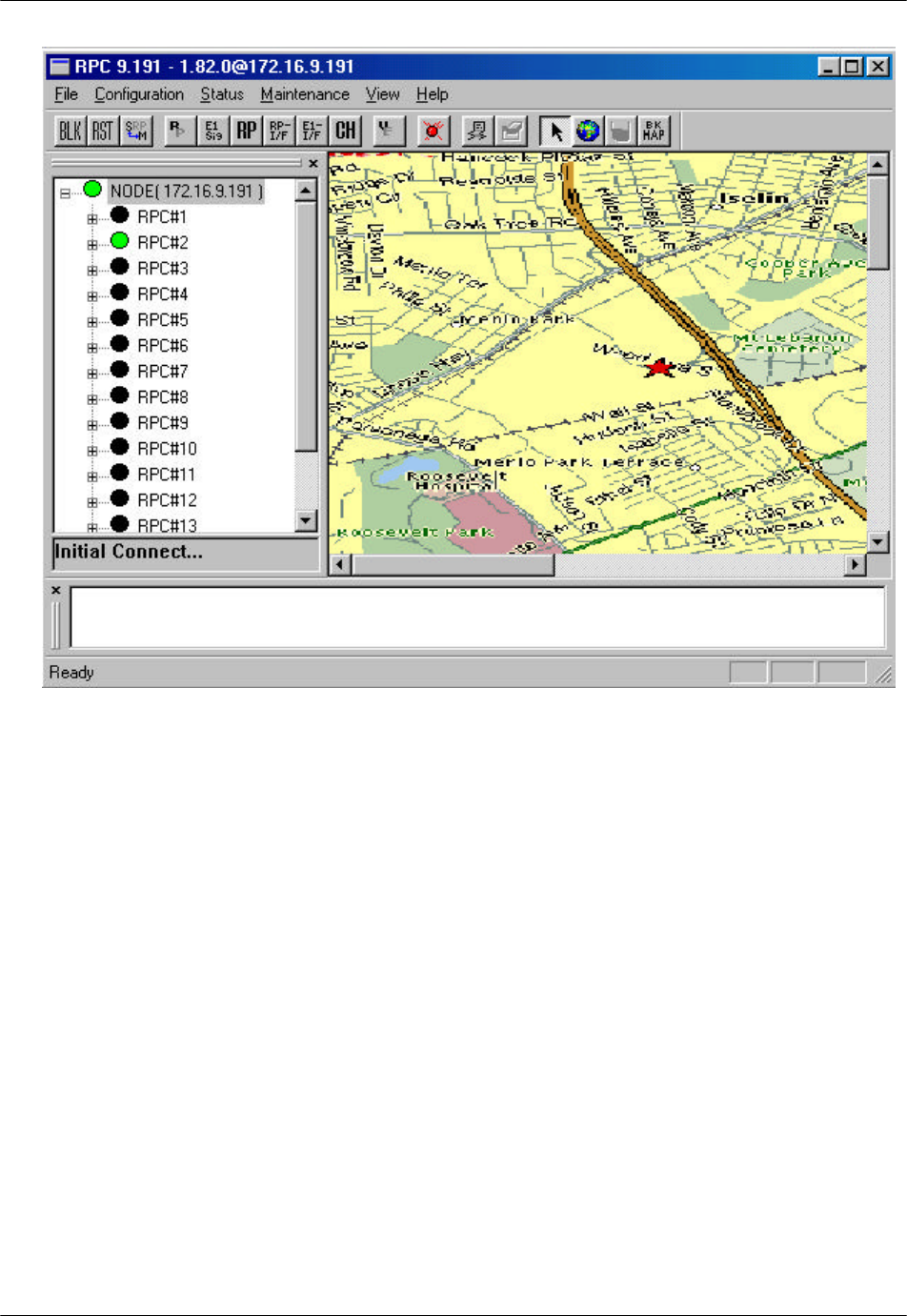
6
Figure 4-7: RPC Window with Background Image
4. To select another background image other than those on the Bitmap field,
click the New button. The Open window appears, as illustrated in Figure 4-8.
RPC/RP Manual RPC/RP Configuration
19June2000 WLL-RPC/RP-IN/UM-1.0
4-
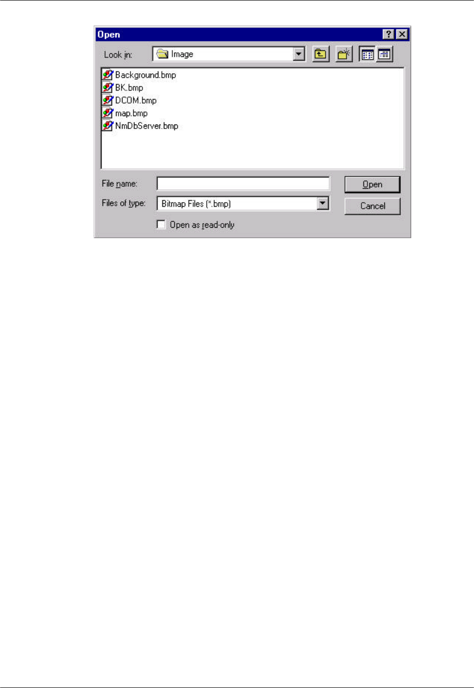
7
Figure 4-8: Open Window
5. Select the target bitmap file and click Open. The selected image file is added
to the Bitmap list and displayed on the Preview field. Click OK to paste the
image to the background of the Status View window if users are satisfied
with the image. A similar window appears, as illustrated previously in Figure
4-7.
4.1.2 Add RPC Icons on the Map
RPC icons can be added to the background map to highlight the location
information of the RPCs. They can be added, deleted or moved. All map
information is stored in the database.
1. To add an RPC icon to the map click the Draw RPC Node button on the RPC
window and click again on the target location of the map. The Property
window opens as shown in Figure 4-9.

RPC/RP Configuration RPC/RP Manual
WLL-RPC/RP-IN/UM-1.0 19June2000
4-
8
Figure 4-9: RPC Property Window
2. Users enter the caption name, select the desired RPC number, enter the
address for that RPC, and click Finish. The RPC icon appears on the map
and the data are stored in the database, as illustrated in the figure below.
RPC/RP Manual RPC/RP Configuration
19June2000 WLL-RPC/RP-IN/UM-1.0
4-
9
Figure 4-10: RPC Window with RPC icons on the Map
3. The RPC icons can be moved, deleted, or moved to the front or back of the
background map. Their properties can also be modified. To perform these
operations right click the target RPC icon and select the relevant option from
the pop-up menu.
4.1.3 Add RP Icons
RP icons can be added to the map under the dominant RPC. Follow the steps
below to perform the operation.
1. Double click the target RPC to access the blank Status View window and to
enable the Draw RP Node button. Now users can add the same background
map to the window. Following the procedure in the previous section to add
the background map. To add the RP icons on the map, click the Draw RP
Node button and click again on the target location of the map. The RP
Property window opens as illustrated in Figure 4-11.
RPC/RP Configuration RPC/RP Manual
WLL-RPC/RP-IN/UM-1.0 19June2000
4-
10
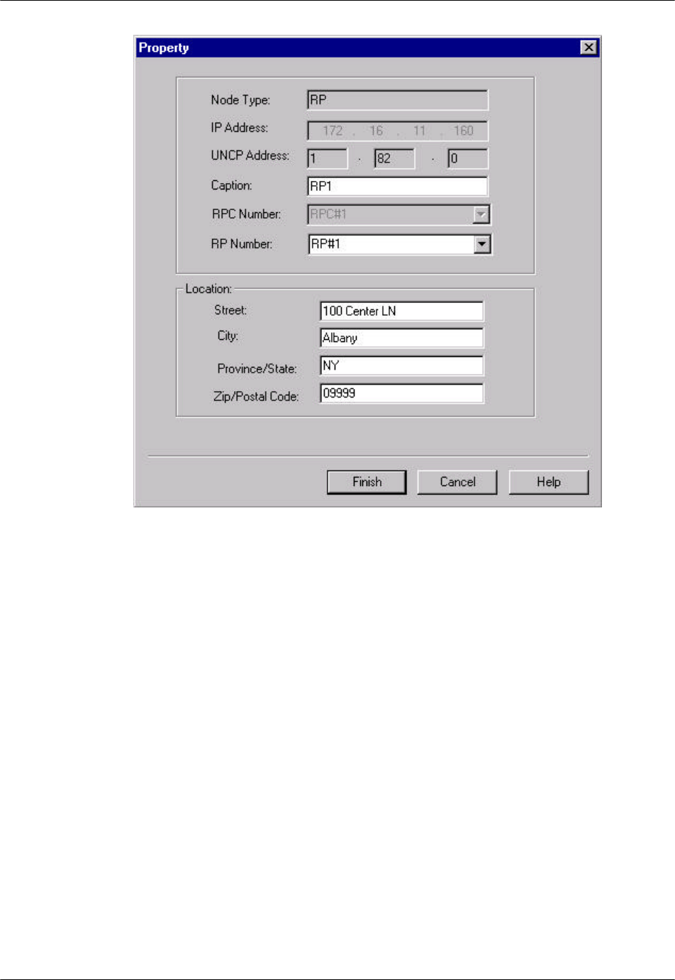
Figure 4-11: RP Property Window
2. This window is similar to that in Figure 4-9. Enter the relevant data into the
fields and click Finish. The RP icon appears on the map and the data are
stored in the database. Repeat this process to add as many RP icons as
needed. Figure 4-12 illustrates a map with three RP icons.
RPC/RP Manual RPC/RP Configuration
19June2000 WLL-RPC/RP-IN/UM-1.0
4-
11
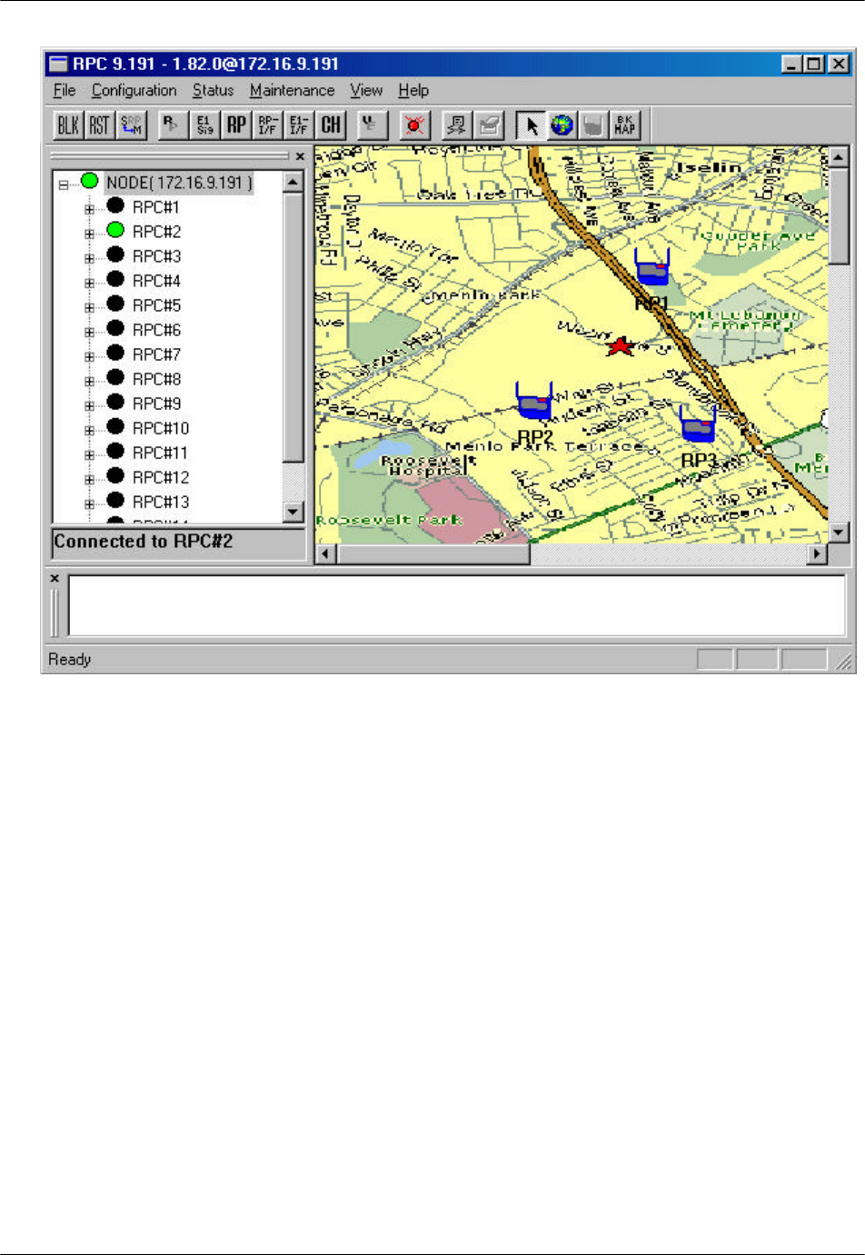
Figure 4-12: RP Map Window
3. To return to the RPC map, click Node on the Unit View window. To re-
access the RP map, double click the target RPC icon on the RPC map.
4. The RP icons can be moved, deleted, or moved to the front or back of the
background map. Their properties can also be modified. To perform these
operations right click the target RP icon and select the relevant option from
the pop-up menu.
4.2 RPC Configuration
This section describes the procedures of provisioning an RPC. Double click the
target RPC node on the Main View window to open the Connect RPCs window.
Select the target RPCs and click OK. This opens the RPC window, as illustrated
in Figure 4-13. With this window open we can perform various types of
configuration to the connected RPCs.