UTStarcom Korea Technologies UTS-EA7H75B Wireless Local Loop Fixed Terminal User Manual Cover
UTStarcom Korea Technologies Ltd. Wireless Local Loop Fixed Terminal Cover
Contents
Manual 4
RPC/RP Configuration RPC/RP Manual
WLL-RPC/RP-IN/UM-1.0 19June2000
4-
12
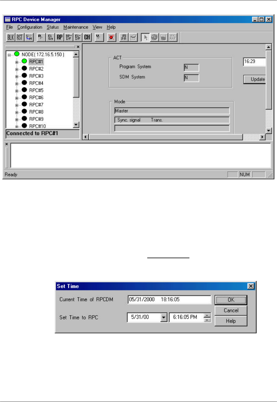
Figure 4-13: RPC Window
4.2.1 Set Time
To set the system time, follow the procedures below:
1. Click the Set Time option on the Configuration pull-down menu. The Set
Time window appears, as shown in the figure below.
Figure 4-14: Set Time Window
2. By default the RPC time is set to the current time of the PC. Set new date and
time to RPC if necessary. Make necessary adjustment using the Arrow
RPC/RP Manual RPC/RP Configuration
19June2000 WLL-RPC/RP-IN/UM-1.0
4-
13
buttons in the fields. Click OK to accept the setting or Cancel to stop the
transaction.
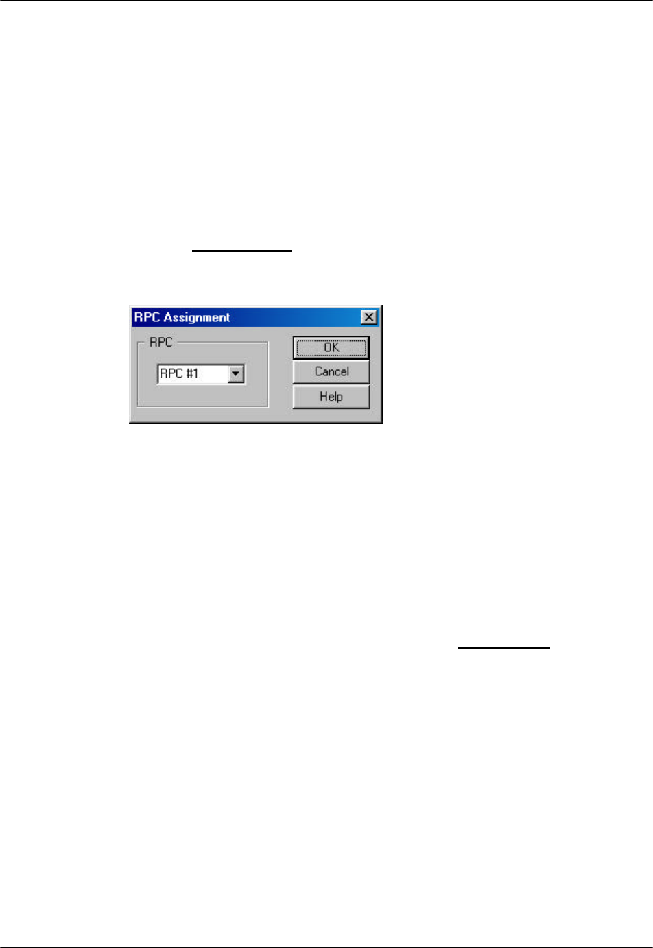
4.2.2 RPC Change
Sometimes the operation data for an RPC may not be compatible to the hosting
RPC. Use this function to make changes to the SDM (System Data Memory) so
that it can accommodate the hosting RPC. Before making any change, the RPC
device manager will disconnect from the RPC.
1. From the Configuration main menu, select RPC Change. This opens the
RPC Assignment window, as illustrated in the figure below.
Figure 4-15: RPC Assignment Window
2. Select the target RPC and click OK. This will change the SDM to fit the
target RPC.
3. If this command doesn’t work, exit the current Netman session and restart.
4.2.3 Unit Control
The Unit Control option can be accessed through the Maintenance pull-down
menu. It has the following functions:
• Blockade: block or unblock RPIF, E1IF, RPCs, RPs
• TimeSlot Layout: configure the RP control channel time slot
• Maintenance: set or cancel system maintenance
• Master RP: change Master RP
• RPC Sync: RPC Synchronization
• Online Trace: retrieve the information of the active RP
RPC/RP Configuration RPC/RP Manual
WLL-RPC/RP-IN/UM-1.0 19June2000
4-
14
4.2.3.1 Blockade/Unblockade
The Blockade option is used to block or unblock RP interface, E1 interface, RPs,
or the entire RPC. Use this function to block traffic from a malfunctioning
device. It is also used when units are replaced. Netman 2000 must be connected
to the WLL/V5WLL in order to perform this function. Another important usage
of this option is to regain the synchronization of the slave RPCs upon the recovery
of the master RPC.
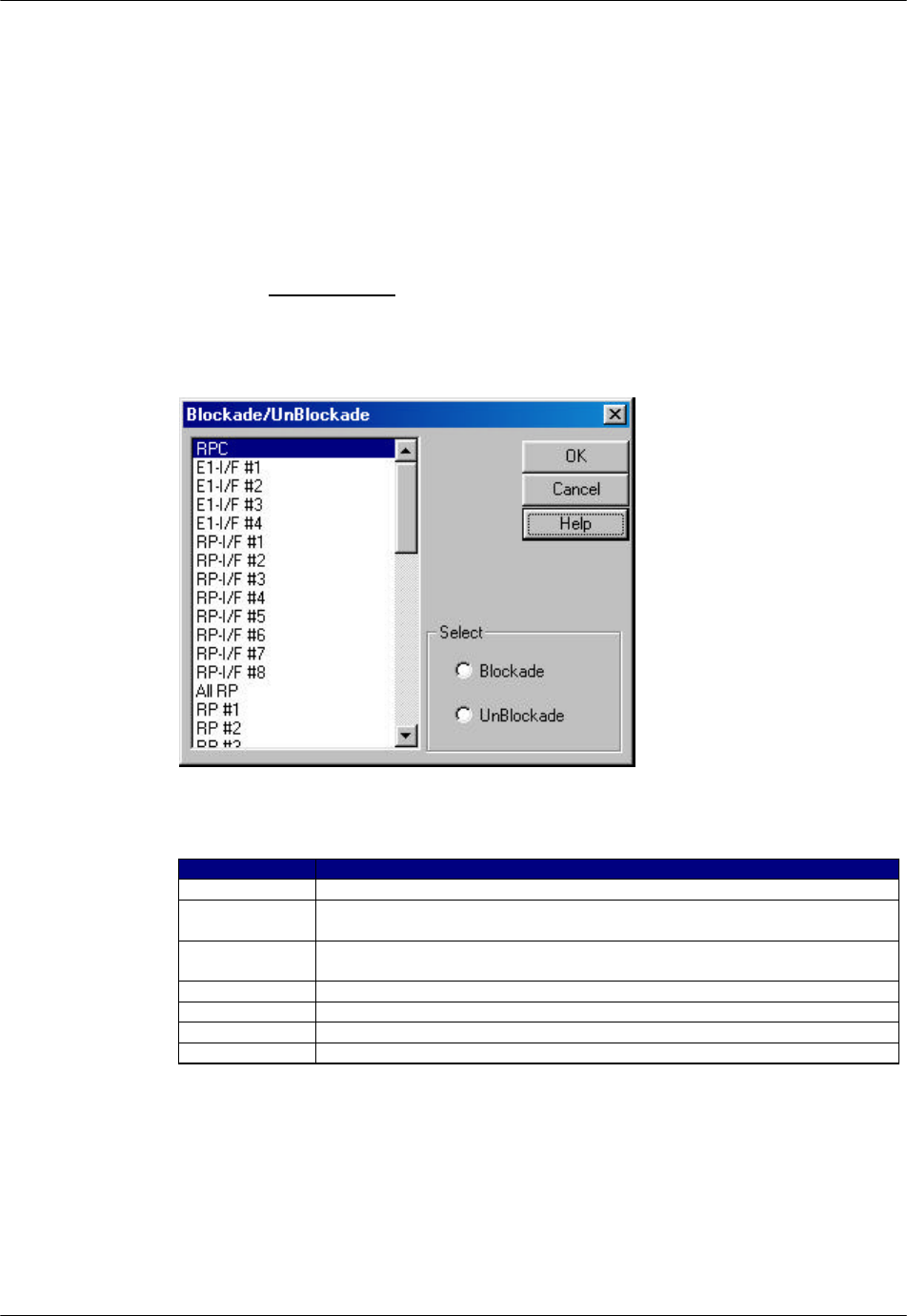
1. From the Maintenance main menu, select Unit Control and then Blockade.
This opens the Blockade/Unblockade window, as displayed in the figure
below.
Figure 4-16: Blockade/Unblockade Window
Field Name Description
RPC The entire RPC, including all the units under its control
E1-I/F #… E1 interface. Each RPC uses 4 E1 interfaces to communicate with
WLL/V5WLL.
RP-I/F #… RP interface. RPC uss 8 RP interfaces to control RPs. Each RP
interface is connected to 4 RPs.
All RP All the 32 RPs
RP #… Individual RP. There are altogether 32 RPs under each RPC.
Blockade If this radio button is selected, the selected unit is blocked.
UnBlockade If this radio button is selected, the selected unit is unblocked.
Table 4-1: Blockade/Unblockade Window Field Description
2. Select the target E1 interface, RP interface, RP, or RPC, and then select
Blockade or Unblockade. Click OK. Selecting RPC will block or unblock all
RPC/RP Manual RPC/RP Configuration
19June2000 WLL-RPC/RP-IN/UM-1.0
4-
15
the units controlled by the RPC. No new calls will be accepted and all the
calls in progress are allowed to complete and then dropped.
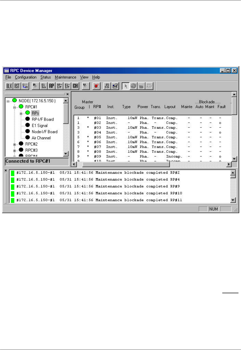
3. When the action is implemented, the system displays a message in the Self
Message window, and the Status View window will also show the Blockade
result, as illustrated in the figure below. Use the window to verify the result.
Figure 4-17: Self Message and Status View window for Blockade
F NOTE: If an RPC or all RPs are blocked, calls cannot be made.
4. Zero “o” in the Blockade Maint column means the unit is blocked, and dash “-
” means the unit is unblocked. The Status and the Self Messages windows
both indicate that RP#1 and RP#2 are blocked.
5. There are two ways to access the Status View window. One is to click Status
and then the relevant options: RPC, RPs, RP-I/F Board, E1 Signal, Node-I/F
Board, Air Channel, or TimeSlot Status. The other is to click the target item
on the left frame of the RPC window. In either case the Status View window
opens on the right frame. Of course, one can always access the window by
clicking the relevant toolbar.
RPC/RP Configuration RPC/RP Manual
WLL-RPC/RP-IN/UM-1.0 19June2000
4-
16
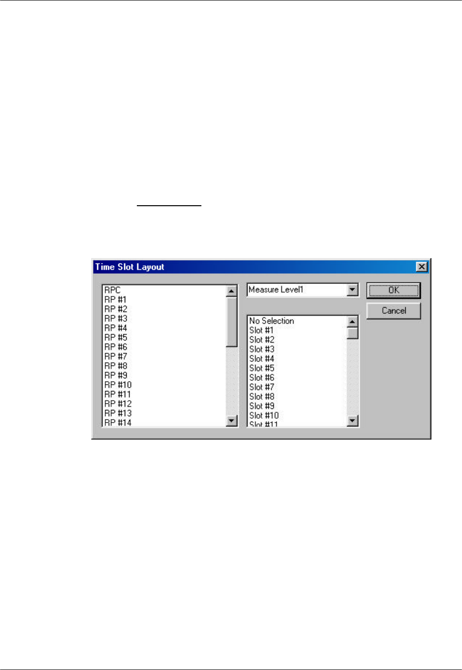
4.2.3.2 TimeSlot Layout
F WARNING: Users are NOT recommended to make changes to the settings of the
Time Slot. Use with caution!
When connected to an RPC, use this function to reconfigure the RP control
channel time slot. This function is used to complete the RP configuration and
make it usable. This function applies to both RPCs and RPs.
1. Before configuring the time slot, use the Blockade function to block the target
RPC or PC.
2. From the Maintenance main menu, select Unit Control and then TimeSlot
Layout. This opens the Time Slot Layout window, as shown in the figure
below.
Figure 4-18: Time Slot Layout Window
3. Select the target RPC or RP.
4. Select Measure Level1. If separation is not completed, try another one from
Measure Level2 through Measure Level4. Selecting No Selection may
accelerate separation.
5. Select No Selection. If selection must be made, select one from Slot #1
through Slot #80.
6. Click OK to close the window.
RPC/RP Manual RPC/RP Configuration
19June2000 WLL-RPC/RP-IN/UM-1.0
4-
17
7. Unblock the RPC or RP.
F NOTE: The Time Slot Layout window is for configuration purpose only. Actual
separation is done when the target RPC or RP is unblocked.
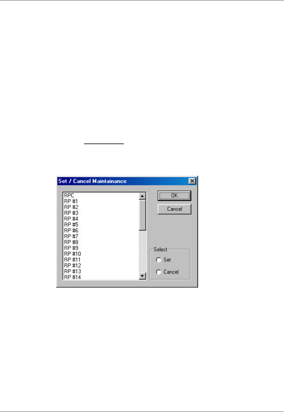
4.2.3.3 Maintenance
Use this function to set RPC maintenance status, test RPs, and do other
configuration. Eligible units are fully installed RPCs and installed RPs.
F NOTE: General PSs can not use RP when maintenance is under way.
1. From the Maintenance main menu, click Unit Control, and then
Maintenance. The Set/Cancel Maintenance window opens, as displayed in
the figure below.
Figure 4-19: Set / Cancel Maintenance Window
2. Select the target RPC or RP, and click Set to set the maintenance status or
Cancel to remove the status.
3. Click OK to accept the selection and close the window.
RPC/RP Configuration RPC/RP Manual
WLL-RPC/RP-IN/UM-1.0 19June2000
4-
18
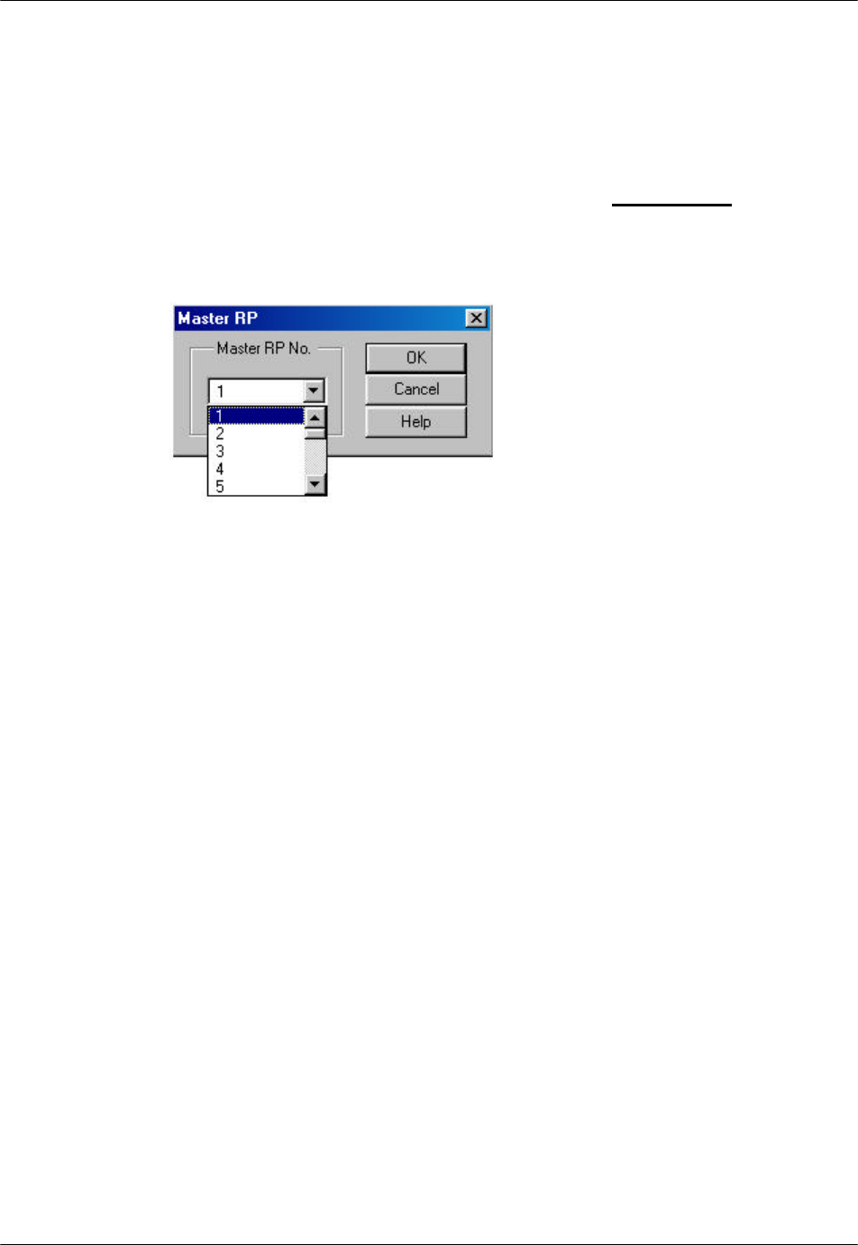
4.2.3.4 Change Master RP
For the operation in a group control mode, it sometimes becomes necessary to
switch a master RP to a slave RP, because the master RP is faulty or because the
NMS operation requires the switch. Use this feature to switch the function.
1. Select Unit Control, and then Master RP from the Maintenance pull-down
menu. The Master RP window appears as shown in the figure below.
Another way to access the window is to click the Change Master RP toolbar.
Figure 4-20: Master RP Window
2. Click the Arrow button in the Master RP No. field to get a list of all the 32
RP numbers. Select the RP to be the new master and click OK. That RP
becomes the new master RP. The Self Message window displays a message,
indicating the change has been made. The change can also be verified by
viewing the RP status.
F NOTE: Each group can have a maximum of 8 RPs.
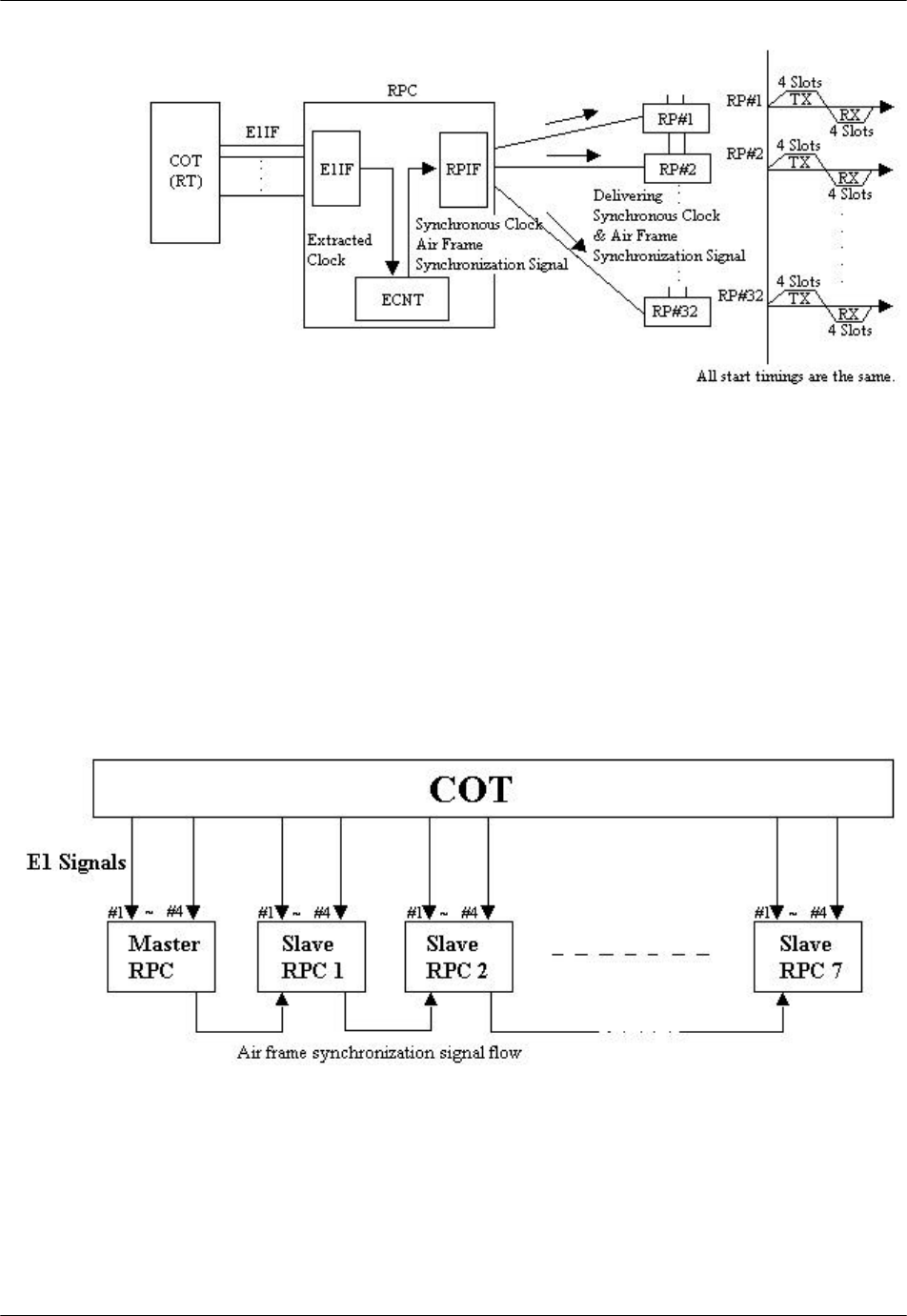
4.2.3.5 RPC Synchronization
The ECNT board on the RPC generates the synchronous clock and the air frame
synchronization signal by extracting clock from the E1 interface signal on the E1-
IF boards, and delivers them to RPs through the RP-IF boards. As a result, all the
RPs that are controlled by the same RPC are operating synchronously. The
following figure illustrates the process of clock synchronization and air frame
synchronization for one RPC.
RPC/RP Manual RPC/RP Configuration
19June2000 WLL-RPC/RP-IN/UM-1.0
4-
19
Figure 4-21: Clock Synchronization and Frame Synchronization in One RPC
However, RPs that belong to different RPCs do not automatically operate with air
frame synchronization. This causes the inefficienct air channel usage. To redress
the problem, the synchronization group is created which includes as many as 8
RPCs. Those RPCs are connected by cables as open daisy chain, through which
the air frame synchronization signal is transmitted. The signal is shared by the
RPCs, so that the air frames of the RPs among the RPCs are synchronized. The
RPC which generates the air frame synchronization signal is named “Master”.
The RPCs which receive the signal are called “Slave”. The following figure
displays such a synchronization model.
Figure 4-22: Wired Air Frame Synchronization Group Model
The master or slave mode is set using the rotary switches on the front of the
ECNT board. When the master RPC fails during the operation, the first slave
RPC in the synchronization signal flow becomes the provisional master RPC.

RPC/RP Configuration RPC/RP Manual
WLL-RPC/RP-IN/UM-1.0 19June2000
4-
20
Upon the restoration and restart of the failed master RPC, the first slave RPC
needs to be blocked and re-synchronized in order to regain synchronization. This
process is implemented through Netman.
1. From the Maintenance pull-down menu, select Unit Control, and then RPC
Sync. The RPC Synchronization window opens, as shown in the figure
below.
Figure 4-23: RPC Synchronization Window
2. Click the RPC blockage radio button to block the slave RPCs. Click OK to
execute the command. Verify the blockage by checking the RPC Status
window and the Self Message window.
3. Return to the RPC Synchronization window and click the RPC
synchronization radio button. Click OK to synchronize the slave RPCs.
After the command is implemented, the slave RPCs become synchronous in
operation to the upstream RPCs.
4.2.3.6 Online Trace
The Online Trace feature is used to check the time slot status of the RPs.
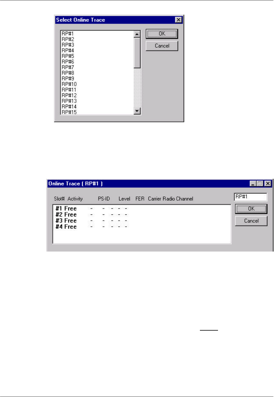
1. From the Configuration main menu, select Unit Control, and then Online
Trace. This opens the Select Online Trace window, as illustrated in the
figure below.
RPC/RP Manual RPC/RP Configuration
19June2000 WLL-RPC/RP-IN/UM-1.0
4-
21
Figure 4-24: Select Online Trace Window
2. Click to highlight the target RP# and click OK. This opens the Online Trace
window, as shown below.
Figure 4-25: Online Trace Window
3. This window displays the relevant Time Slot status information about the
target RP.
4.2.4 Function Status
The Status option windows can be accessed through the Status pull-down menu.
The following functions are available from the Status option:
• Collect and display the status for:
- RPC
RPC/RP Configuration RPC/RP Manual
WLL-RPC/RP-IN/UM-1.0 19June2000
4-
22
- RPs
- RP-I/F Board
- E1 Signal
- Node-I/F Board
- Air Channel
- TimeSlot Status
• Collect hourly traffic data for RPCs and RPs
• View configuration data for each RP control channel
• Verify configuration results
4.2.4.1 RPC Status
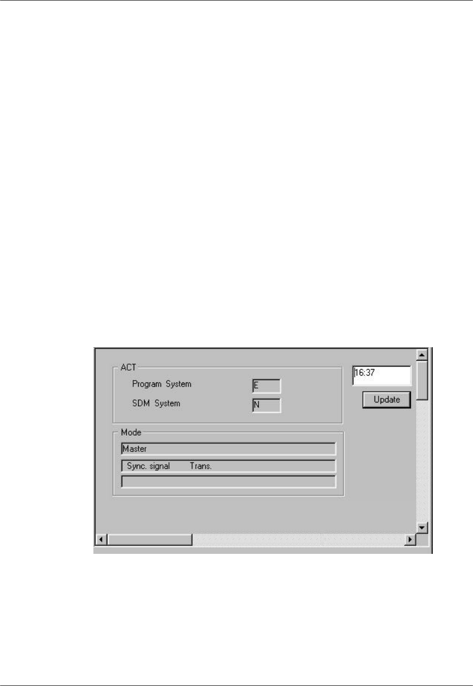
1. To view the status of the current RPC, click RPC from the Status option.
Another way to open the RPC Status window is to click the RPC Status
button. The RPC status is displayed on the Status View window, as shown in
the figure below.
F NOTE: The following figure is cut out from the RPC window. The other Status
View windows in Section 4.2.4 are also cropped from the overall RPC window.
Figure 4-26: RPC Status Window

RPC/RP Manual RPC/RP Configuration
19June2000 WLL-RPC/RP-IN/UM-1.0
4-
23
Field Name Description
ACT The active SDM or PDM system for RPC running
Program System PDM system. There are two plane memory areas for the
program data: N and E. Any one can be active or standby.
SDM System SDM system. There are two plane memory areas for the
operation data: N and E. Any one can be active or standby.
Update Retrieve the latest mode information and display the time
when the mode information is updated.
Mode Display mode information for the current RPC, such as,
master/slave status, synchronization status, transmission
status, etc. The following rows describe various mode
displays.
Mode Display Description
Master Master RPC - the RPC that generates the air frame
synchronization signal.
Slave Slave RPC - the RPC that receives the air frame
synchronization signal.
Sync. signal Trans. The RPC transmits the synchronization signal to the slave
RPC or the next slave RPC.
Sync. signal Stop The RPC doesn’t transmit the synchronization signal to the
slave RPC or the next slave RPC.
Sync. between RPC Sync. The slave RPC synchronizes to the upstream RPC.
Sync. between RPC Async. The slave RPC doesn’t synchronize to the upstream RPC.
Table 4-2: RPC Status Window Field Description
2. This window is for view only. In this instance, there is no special meaning for
N or E. It simply displays which system is active. Refer to Section 4.3 for the
description of the N and E systems.
4.2.4.2 RP Status
Use the RP Status option to monitor the operation status of individual RPs and to
verify any change made to the RP configuration and setting.
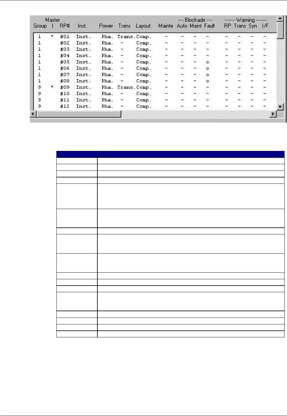
1. To access the RP Status window, click Status, then Status, and then RPs.
Another way to display the window is to click the RP Status button. The RP
status is displayed on the Status View window, as shown in the figure below.
RPC/RP Configuration RPC/RP Manual
WLL-RPC/RP-IN/UM-1.0 19June2000
4-
24
Figure 4-27: RPs Operation Status View window
Field Name Description
Group The ID number of the group to which the RP belongs
Master The sign * indicates the master RP.
RP# Radio port ID number
Inst. Installation status. “Inst.” Indicates that the RP has been installed.
Power The voltage of power. Usually it is 10mW. There are two power supply
state:
Pha. - supplied from RPC (Phantom)
Loc. - supplied from RP power unit (Local)
Trans. Transmission state for control channel. Group control maximizes the
number of channels available for traffic by allowing one control channel to
control up to 8 RPs.
Layout Configuration of the control channel: completed/incompleted.
Mainte Maintenance state:
o indicates the maintenance is configurated.
- indicates the maintenance is not configured.
Blockade Blockage state:
o indicates the unit is blocked.
- indicates the unit is not blocked.
Auto Automatically blocked by automatic reconfiguration processing
Maint Blocked manually by HOST or Netman
Fault Cut off from operation system due to unit trouble
Warning Warning state:
o indicates the existence of a warning.
- indicates no warning exits.
RP RP interface detects RP suspension.
Trans. RP transmission power is incorrect.
Syn RP synchronization is lost.
I/F RP interface detects cut-off from RP.
Table 4-3: RP Status Window Field Description
2. This window displays the operational status for all the RPs controlled by the
target RPC. Click the Update button to retrieve the current RP status. The

RPC/RP Manual RPC/RP Configuration
19June2000 WLL-RPC/RP-IN/UM-1.0
4-
25
time will be displayed in the box above the button, indicating the time when
the data are updated.
3. With this window you can verify RP installation status, monitor alarms, power
supply status, and transmission information, and identify areas of trouble.
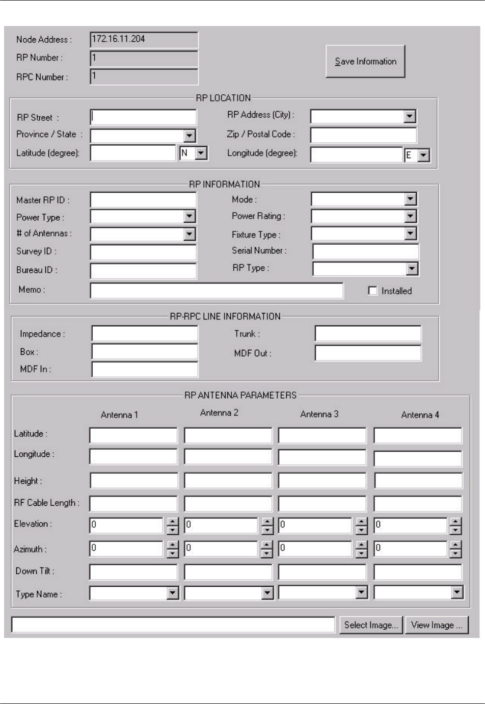
4. If you want to view the status for an individual RP, you may access such a
window by clicking the “+” sign to the left of RPs on the Unit View window.
This displays all the RPs under the RPC. Click the target RP and the Status
View window opens for that RP, as illustrated in Figure 4-28. With this
window you may view or enter the following information about that RP:
• Node Address
• RP Number
• RPC Number
• RP Location
• RP Information
• RP-RPC Line Information
• RP Antenna Parameters
F NOTE: This is an optional information window. The information is stored on
Netman 2000 and will be used in network management, network optimization, and
value-added services, such as location services. The information entered does not
affect the operation of the RP.
RPC/RP Configuration RPC/RP Manual
WLL-RPC/RP-IN/UM-1.0 19June2000
4-
26
Figure 4-28: Status View window for One Individual RP

RPC/RP Manual RPC/RP Configuration
19June2000 WLL-RPC/RP-IN/UM-1.0
4-
27
Field Name Description
Node Address The IP address of the node to which the RP is associated
RP Number The ID number of the RP
RPC Number The ID number of the RPC which controls the RP
RP Location The physical location of the RP
RP Street The street name of the location
Province/State The province/state name of the location. Select from the drop-down list.
RP Address (City) The city name of the location. Select from the drop-down list.
Zip/Postal Code Zip/Postal Code of the location
Latitude (degree) Latitude degree of the RP location.
Longitude (degree) Longitude degree of the RP location
RP information Information about the RP operation status
Master RP ID The ID number of the Master RP
Power Type There are two power supply patterns:
Local - the power is supplied from the RP power unit.
Remo - the power is supplied from the RPC.
Select from the drop-down list.
# of Antennas The number of the antennas the RP has. The indoor or outdoor 10mW RP
has 2 antennas, and the outdoor 200mW RP has 4 antennas. Select from
the drop-down list.
Survey ID The ID number of the survey
Bureau ID The ID number of the bureau
Memo Short note
Mode Master RP or slave RP. Select from the drop-down list.
Power Rating Power: 10mW or 200mW. Select from the drop-down list.
Fixture Type The way the RP is mounted. Select from the drop-down list.
Serial Number The serial number of the RP
RP Type Indoor or outdoor type. Select from the drop-down list.
Installed If the RP is installed, check the box.
RP-RPC Line Information Information about the communication cable connecting the RP and the
controlling RPC
Impedance The resistance of the communication cable
Box The specification of the switch box. For instance, a 200mW RP can have
the following specification:
Power Voltage – 220V AC
Dimension – 217mm x 258.5mm x 98mm
Weight – about 4.1 kg
MDF In Main Distribution Frame. The wiring arrangement which connects the
cable coming in from outside
MDF Out Main Distribution Frame. The wiring arrangement which connects the
cable going out from inside
Trunk The communication line between the RP and the RPC
RP Antenna Parameters The specification of the RP antennas
Latitude Latitude of the antenna location (string) (WGS94)
Longitude Longitude of the antenna location
Height Height of the antenna
RF Cable Length Radio Frequency cable length
Elevation Height above the ground
Azimuth The horizontal angle which the radiating lobe of an antenna makes in
angular degrees, in a clockwise direction, from a north-south line in the
northern hemisphere. In the southern hemisphere, the reference is the
south-north line.
Down Tilt The extent with which the antenna mechanically slopes downward
Type Name Name of the antenna type, for instance, OMNI antenna (Co-Liner antenna)
Select Image Selet an image file in .bmp format which presents the mounted RP.
View Image Use the Image Viewer to view the selected image file.
Table 4-4: RP Status Window Field Description
RPC/RP Configuration RPC/RP Manual
WLL-RPC/RP-IN/UM-1.0 19June2000
4-
28
5. The window in the above window may not display all the information in one
screen. Use the horizontal and vertical scroll bars to see all the information.
4.2.4.3 RP-I/F Board Status
With the RP-I/F Board Status View window you can view or verify such RP
interface operational statuses as RP-IF#, installation, or warning.
1. To access the RP-I/F Status View window, click Status, then the Status
option, and then the RP-I/F Board option. This opens the RP-IF Status
View window on the RPC window, as illustrated in the figure below.
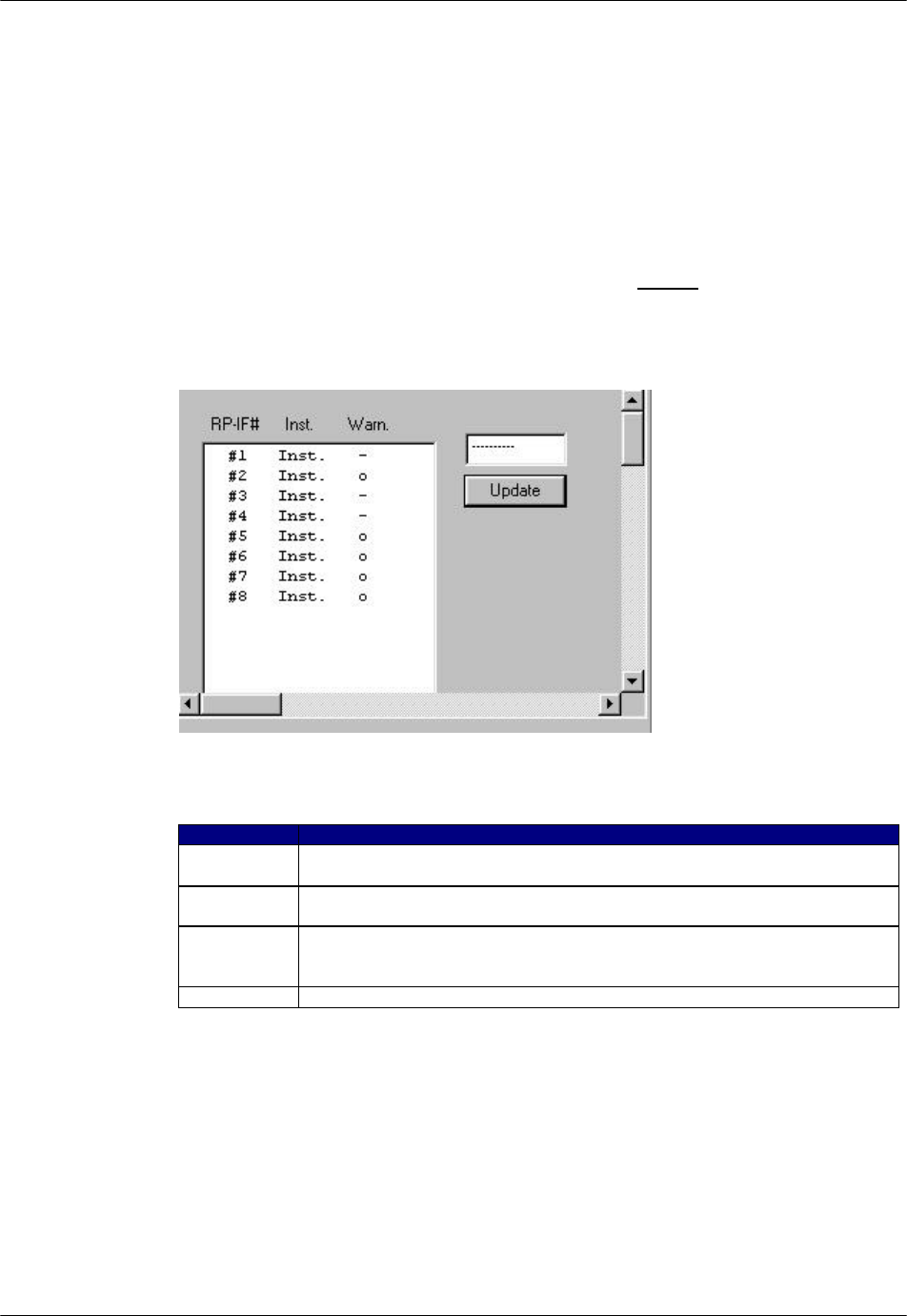
Figure 4-29: RP-IF Status View window
Field Name Description
RP-IF# The ID number of the RF-IF#. Each RPC can have 8 RP interface modules,
each of which can be connected to 4 RPs.
Inst The installation status of the RP interface. Inst in the column Indicates that
the RP-IF is installed.
Warn The warning status of the RP interface.
o indicates the existence of a warning.
- indicates no warning exits.
Update Retrieve the latest status information.
Table 4-5: RP-IF Status View window Field Description
2. Click Update to display the current status.
RPC/RP Manual RPC/RP Configuration
19June2000 WLL-RPC/RP-IN/UM-1.0
4-
29
4.2.4.4 E1 Signal Status
Each RPC can have 4 E1 lines to communicate with the WLL/V5WLL.
However, the D-channel can be established on only one E1 line. The E1 line on
which the D-channel is established is named the master E1 and the other three E1
lines are named slave E1s. If the master E1 line is down, a slave E1 line will be
promoted by the system to become the master E1. The D-channel can be
established on this slave E1 line. The selection of the master E1 follows the
round-robin order.
Use the E1 Signal option to monitor and verify the operational status of the E1
signal, including four E1 interfaces, E1 warning, Layers 1 through 3, and other
status information.
1. From the Status main menu, select Status, and then E1 Signal. The E1
Signal Status window appears on the right frame of the RPC window, as
shown in the figure below. Another way to open the window is to click the
E1 Status button.
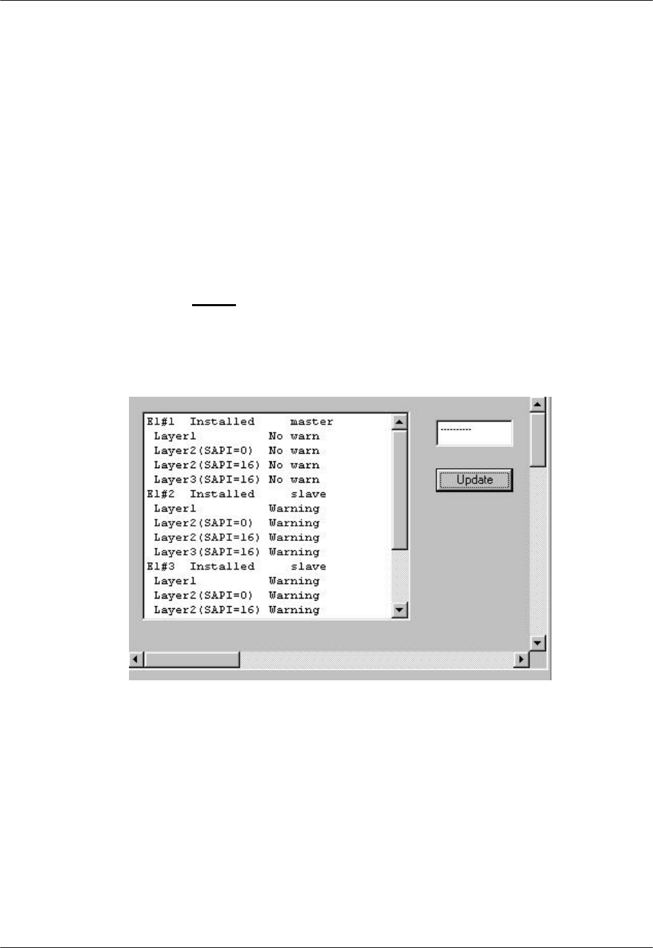
Figure 4-30: E1 Signal Status Window
RPC/RP Configuration RPC/RP Manual
WLL-RPC/RP-IN/UM-1.0 19June2000
4-
30
Field Name Definition
E1#1 Corresponding to E1-I/F#1, Bch#1 - 30
E1#2 Corresponding to E1-I/F#2, Bch#31 - 60
E1#3 Corresponding to E1-I/F#3, Bch#61 - 90
E1#4 Corresponding to E1-I/F#4, Bch#91 - 120
Layer 1 Physical layer with SAPI=0,16
Layer 2 (SAPI=0) Data Link layer for call processing
Layer 2 (SAPI=16) Data Link layer for HOST interface
Layer 3 (SAPI=16) Network layer for HOST interface
Master Master E1 on which D-channel is established.
Slave Slave E1
Warning There is a warning for the E1.
No warn There is no warning for the E1.
Table 4-6: Signal Status Field Name Definition
2. Click Update to display the current status.
4.2.4.5 E1 Interface Status
Each RPC has four E1 interface boards to communicate with the WLL/V5WLL.
Use the E1 Interface option to verify E1 Interface status, monitor alarms, and
identify areas of trouble.
1. From the Status pull-down menu, click Status, and then Node-I/F Board.
This displays the E1 Interface status on the Status View window, as shown in
the figure below. Another way to open this window is to click the E1-
Interface Status button.
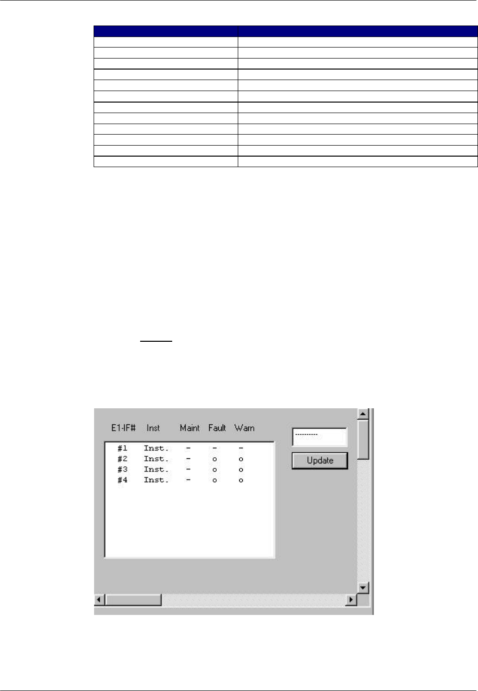
Figure 4-31: E1 Interface Status Window
RPC/RP Manual RPC/RP Configuration
19June2000 WLL-RPC/RP-IN/UM-1.0
4-
31
Field Name Description
E1-IF# E1 interface ID number
Inst Installation state configured by the system operation
data. There are two states: Inst/Uninst.
Maint Blocked manually by HOST or RMT
o indicates blockage.
- indicates no blockage.
Fault Cut off from the operation system due to the unit trouble.
o indicates the existence of error.
- indicates no error exists.
Warn Warning status:
o indicates the existence of warning
- indicates no warning exists.
Table 4-7Table 5-23: E1 Interface Status Window Field Description
3. Click Update to display the current status.
4.2.4.6 Air Channel Status
This function displays the state of wired/wireless channels in use. Use the
Channel Status View window to determine the availability of the channels.
1. To access the Status View window, click the Status pull-down menu, then
Status, and then Air Channel. The channel status is displayed on the Status
View window, as shown in the figure below. The table following the figure
provides the description for each field on the Channel Status View window.
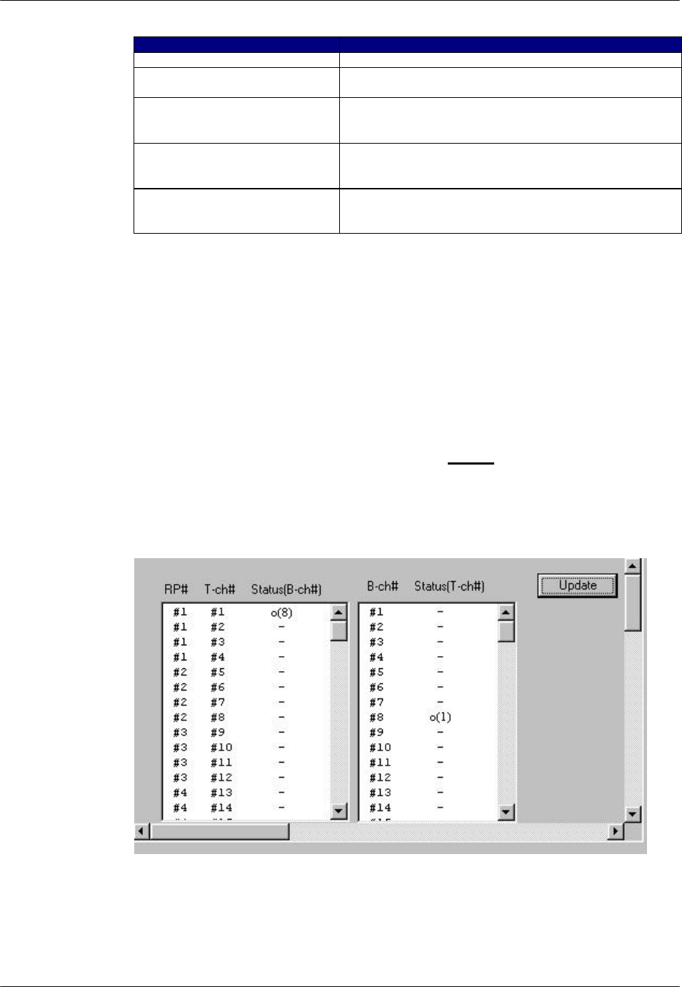
Figure 4-32: Channel Status View window
RPC/RP Configuration RPC/RP Manual
WLL-RPC/RP-IN/UM-1.0 19June2000
4-
32
Field Name Definition
RP# RP ID number
T-ch# Traffic Channel ID number
B-ch# Bearer Channel ID number
Status(B-ch#) An o indicates the B channel enclosed in the parentheses is in use by
the T channel number. In the example above, B channel 8 is in use by
T channel 1.
Status(T-ch#) An o indicates the T channel enclosed in the parentheses is in use by
the B channel number. In the example above, T channel 1 is in use by
B channel 8.
Table 4-8: Channel Status Field Definitions
2. Click the Update button to display the current status.
4.2.4.7 Time Slot Status
This function is used to display the configuration state of each RP’s control
channel.
1. From the Status main menu, click Status, and then TimeSlot Status. This
opens the Time Slot Status window, as shown in the figure below.
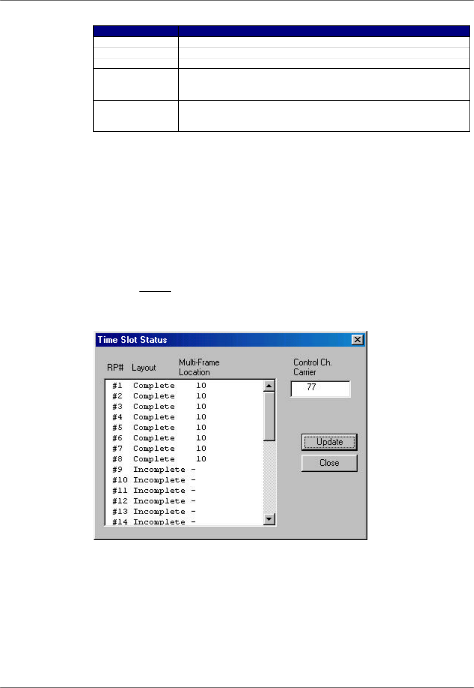
Figure 4-33: Time Slot Status Window

RPC/RP Manual RPC/RP Configuration
19June2000 WLL-RPC/RP-IN/UM-1.0
4-
33
Field Name Description
RP# The ID number of the RP which transmits control channel LCCH
Layout Complete/Incomplete configuration.
Complete: RP has found the control channel.
Incomplete: RP has not been able to find the control channel (e.g.
due to interference).
Multi-Frame Location Position to which the RP transmits control channel LCCH
Control Ch. Carrier Channels over which the RP transmits control channel LCCH
Update Retrieve the latest status information.
Table 4-9: Time Slot Status Window Field Description
2. Click the Update button to get the latest status information. Click Close to
close the window.
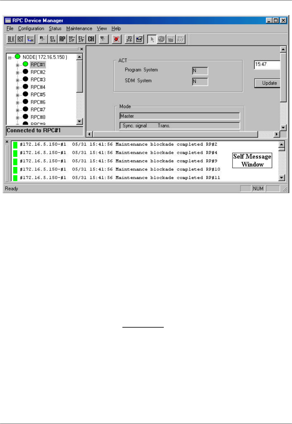
4.2.5 Self Messages
Whenever there is a change in configuration or a new warning is received, a
message will be displayed in the Self Message window, notifying of the situation.
The Self Message View window is located at the bottom of the RPC window.
Figure 4-34 illustrates the Self Message window with event messages.
RPC/RP Configuration RPC/RP Manual
WLL-RPC/RP-IN/UM-1.0 19June2000
4-
34
Figure 4-34: Self Message Window
This Self Message window displays only the event messages received from the
RPCs that are connected to the host RT. In the above example the host RT has
the IP address of 172.16.5 150. This RT controls 15 RPCs. The Self Message
window is updated without the need for special operation action.
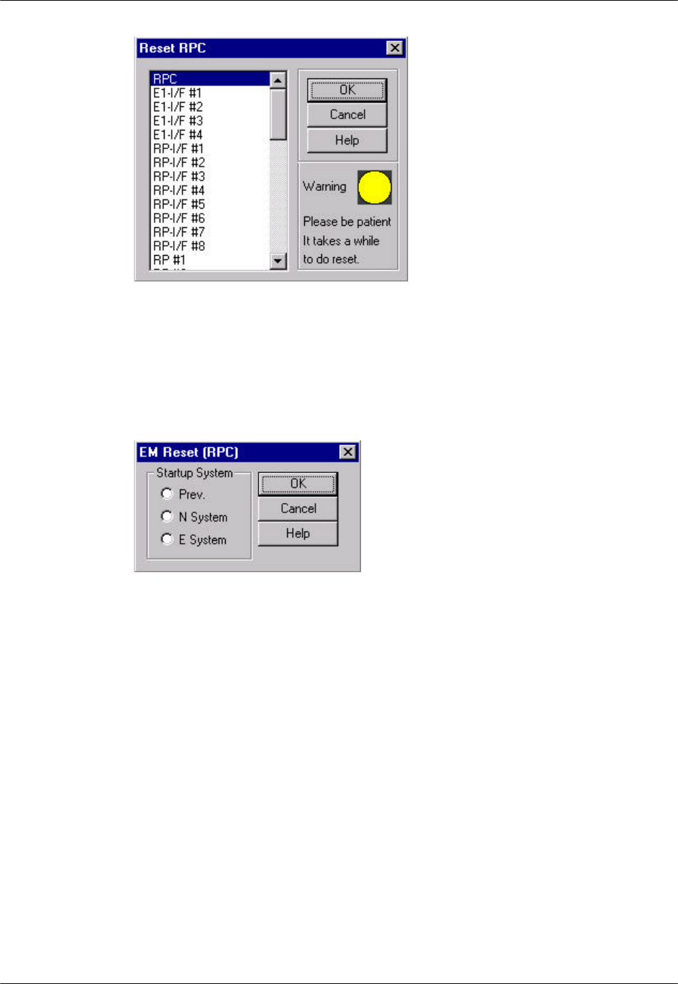
4.2.6 Reset RPC
When a system component experiences trouble and the problem cannot be solved,
it may be necessary to reset that component. RPC resetting may also be needed
after certain provisioning operation.
1. Select Reset from the Maintenance main menu. The Reset RPC window
appears as shown in Figure 4-35.
RPC/RP Manual RPC/RP Configuration
19June2000 WLL-RPC/RP-IN/UM-1.0
4-
35
Figure 4-35: Reset RPC Window
2. Before resetting any component, verify that there are no calls active by
checking the air channel status. Select the target component and click on OK.
If an RPC is selected to be reset the following window opens.
Figure 4-36: EM Reset Window
There are three options for Startup System.
- Prev
- N system
- E system
3. Select the system to be reset and click OK.
4. After EM reset is complete, the RPC is disconnected. To resume normal
operation, reconnect to the RPC.
RPC/RP Configuration RPC/RP Manual
WLL-RPC/RP-IN/UM-1.0 19June2000
4-
36
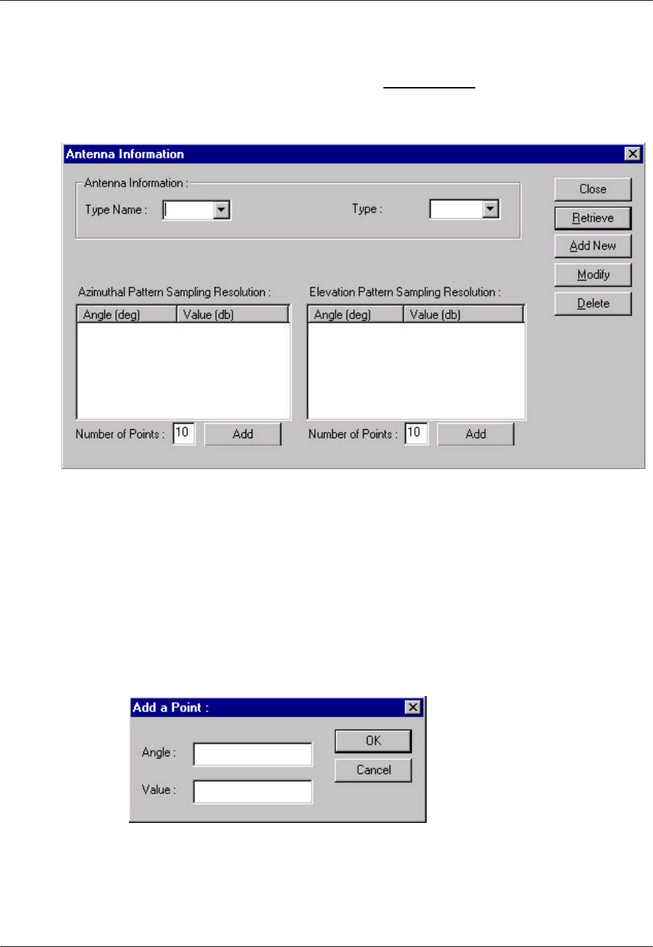
4.2.7 Antenna Information
1. Select Antenna Information from the Maintenance main menu, and the
Antenna Information window opens as shown in Figure 4-37.
Figure 4-37: Antenna Information Window
2. Antenna name and type are read from the database. If new information is
added, click the Add New button and the new information is saved into the
database.
3. If users want to add more pattern resolution, click Add and the Add a Point
window opens as shown in Figure 4-38. Users enter the values and click OK.
The values are added into the list box of the Antenna Information window.
Figure 4-38: Add a Point Window
RPC/RP Manual RPC/RP Configuration
19June2000 WLL-RPC/RP-IN/UM-1.0
4-
37
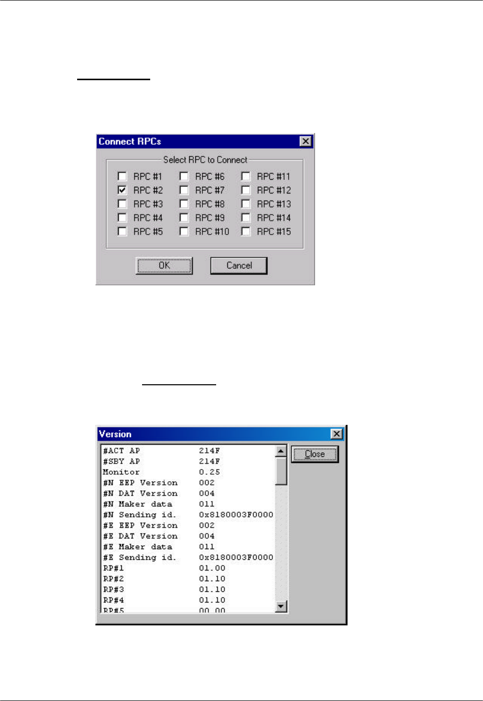
4.2.8 RPC Connection
To change the number of RPCs to be connected, select RPC Connection from the
Configuration main menu, the Connect RPCs window displays as shown in
Figure 4-39. Click the check button of the target RPCs to be connected and click
OK to connect to the selected RPCs.
Figure 4-39: Connect RPCs Window
4.2.9 Version Window
1. From the Configuration pull-down menu, click the Version option. This
opens the Version window, as illustrated in the figure below.
Figure 4-40: Version Window

RPC/RP Configuration RPC/RP Manual
WLL-RPC/RP-IN/UM-1.0 19June2000
4-
38
2. There are two columns in this window. The left column lists the item names.
The right column shows the corresponding version. This window displays the
version of each item in operation.
4.3 Manage RPC Data
RPC data include program data and operation data. RPCs have two plane
memory areas for the program data and two plane memory areas for the operation
data. As a result, the RPC data can be categorized into the following types:
1. For the program data
• PDM (Program Data Memory)-#N
• PDM (Program Data Memory)-#E
2. For the operation data
• SDM (System Data Memory)-#N
• SDM (System Data Memory)-#E
In effect, the RPC continues to run based on 1 SDM and 1 PDM. Therefore,
SDM and PDM have two types of operation status:
1. Active (ACT): the SDM and PDM which are used for RPC running.
2. Standby (STY): the SDM and PDM which are not used for RPC running.
Suppose that an RPC ran based on SDM-#N and PDM-#E, the operation status for
the RPC data systems would be:
• SDM-#N: ACT
• SDM-#E: SBY
• PDM-#N: SBY
• PDM-#E: ACT
These data systems can be manipulated through the options under the
Configuration and Maintenance main menus. Use the procedure in this section
to manage the RPC data.
4.3.1 Program Load
The Program Download option of the Maintenance pull-down menu offers the
function of downloading the program data from Netman 2000 to the SBY PDM of
RPC/RP Manual RPC/RP Configuration
19June2000 WLL-RPC/RP-IN/UM-1.0
4-
39
the target RPC and putting it into operation by switching to the new program data
at the specified time.
F NOTE: It is recommended that program download be done using RMT via
WLL/V5WLL.
During the operation the system prompts you to disconnect the target RPC. Click
OK to disconnect it. After the operation reconnect the RPC.
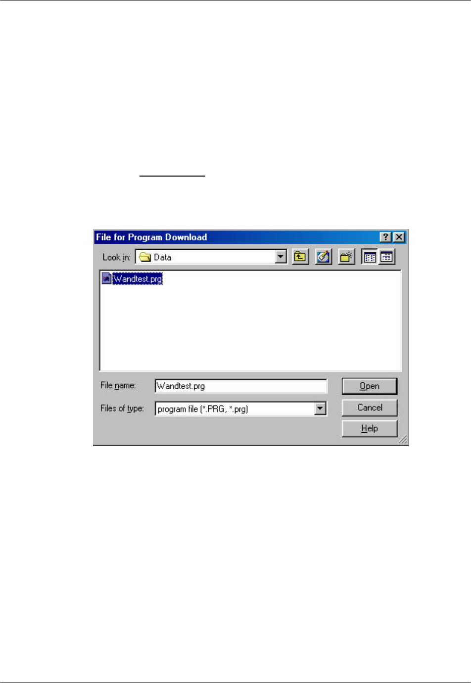
1. Click the Maintenance main menu, select the Program Download option,
and then the Program Load option. This opens the File for Program
Download window, as shown in the figure below.
Figure 4-41: File for Program Download Window
F NOTE: The program file must be in the Netman directory. The proper path
should be: C:\program files\UTStarcom\Netman\data. This rule applies to other
data files and data operation.
2. Select the program data file to be downloaded. The program data file must be
of the .prg or .PRG type. When the Open button is clicked, a confirmation
dialog box opens, as displayed below.
RPC/RP Configuration RPC/RP Manual
WLL-RPC/RP-IN/UM-1.0 19June2000
4-
40
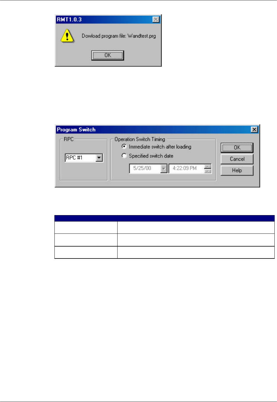
Figure 4-42: Download Confirmation Dialog Box
3. Click OK, and the Program Download window opens, as shown in the figure
below.
Figure 4-43: Program Download Window
Field Name Description
RPC The ID number of the RPC to which the program data are to be
downloaded. Click the Arrow button to make a selection.
Immediate switch after
loading If selected, the RPC will switch to the new program data
immediately after downloading.
Specified switch date If selected, the RPC will switch to the new program data at the
date and time specified in the two fields provided.
Table 4-10: Program Download Window Field Description
4. Select the RPC to which the program data are to be downloaded, and make a
selection in the Operation Switch Timing block. Click OK. The program
data are downloaded to the SBY PDM.
5. After the data have been downloaded, click OK.
4.3.2 Program Switch
Use the Program Switch option to switch the operation status of the SBY PDM
and the ACT PDM.

RPC/RP Manual RPC/RP Configuration
19June2000 WLL-RPC/RP-IN/UM-1.0
4-
41
1. From the Maintenance pull-down menu, select Program Download, and then
Program Switch. The Program Switch window appears, as shown in the
figure below.
Figure 4-44: Program Switch Window
2. This window is exactly the same as the previous one. Make a selection in the
Operation Switch Timing block. If you click the Specified switch date
radio button, specify the date and time for the new program to go into
operation. Click OK to accept the setting or Cancel to stop the transaction.
After switching at the specified time, RPC runs based on the SBY PDM and
each PDM status is switched.
4.3.3 Data Load
Operation data can be loaded and put into operation by selecting the Service Data
options. Use the procedure in this section to load the operation data to the SBY
SDM and to specify the time to switch to the new data.
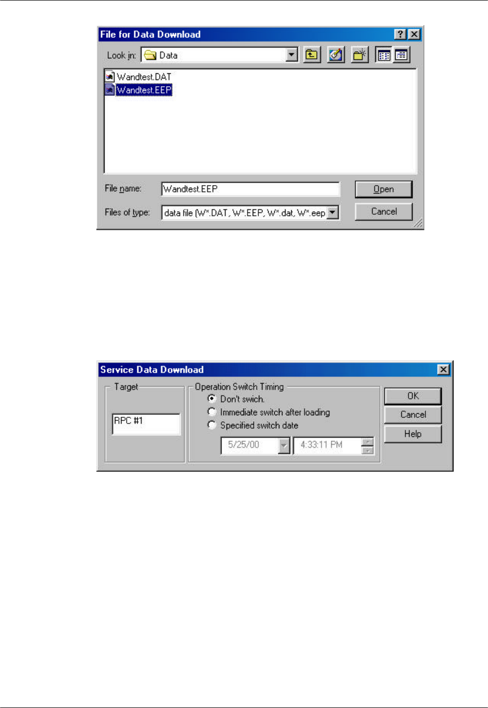
1. From the Configuration pull-down menu, select Service Data, then Data
Download, and then Data load. This opens the File for Data Download
window, as illustrated in the figure below.
RPC/RP Configuration RPC/RP Manual
WLL-RPC/RP-IN/UM-1.0 19June2000
4-
42
Figure 4-45: File for Data Download Window
2. Select the data file to be downloaded. The data file must be of the .DAT or
.EEP type. When the Open button is clicked, a confirmation window opens.
Click OK. This opens the Service Data Download window, as shown in the
figure below.
Figure 4-46: Service Data Download Window
3. Select the target RPC to which to download the data. Make a selection in the
Operation Switch Timing block. If the Specified switch date radio button is
selected, specify the date and time for the switch operation to be executed.
Click OK. The operation data is downloaded to the SBY SDM.
4.3.4 Data Switch
Use the Data Switch option to specify the date and time to switch to the SBY
SDM.
RPC/RP Manual RPC/RP Configuration
19June2000 WLL-RPC/RP-IN/UM-1.0
4-
43
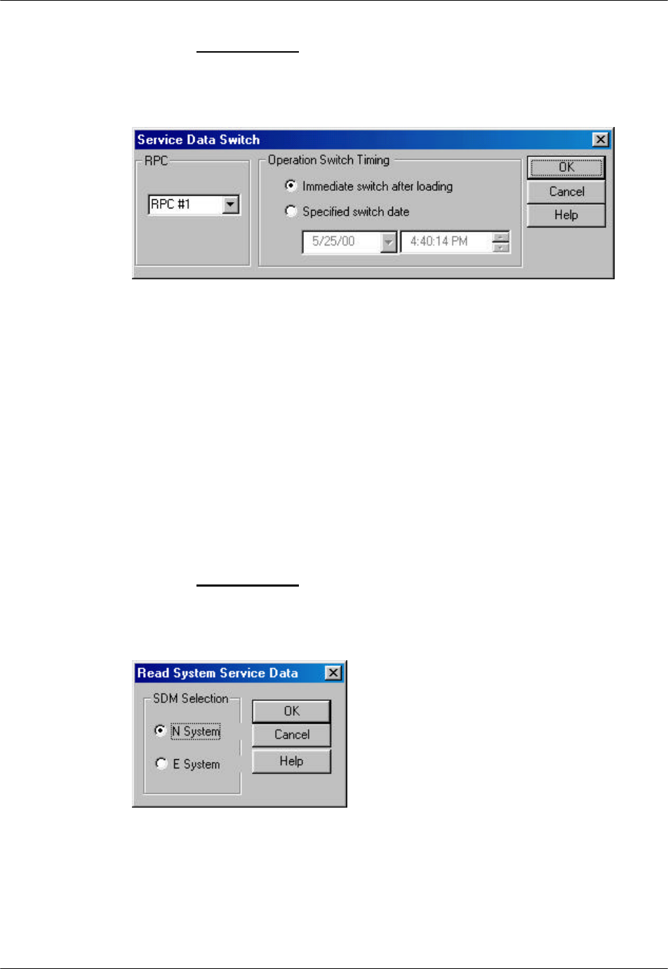
1. From the Configuration pull-down menu, select Service Data, then Data
Download, and then Data Switch. The Service Data Switch window
appears, as shown in the figure below.
Figure 4-47: Service Data Switch Window
2. Select the target RPC. Make a selection in the Operation Switch Timing
block. If you click the Specified switch date radio button, specify the date
and time for the switch operation to be executed. Click OK to accept the
setting. After switching at the specified time, RPC runs based on the SBY
SDM and each SDM status is switched.
4.3.5 Read Data
Use this function to read the operation data from the current RPC to Netman 2000
while the RPC is operating.
1. From the Configuration main menu, select Service Data, and then Read
Data. This opens the Read System Service Data window, as displayed in the
figure below.
Figure 4-48: Read System Service Data Window
RPC/RP Configuration RPC/RP Manual
WLL-RPC/RP-IN/UM-1.0 19June2000
4-
44
Field Name Description
SDM Selection Select one of the two operation data systems: SDM-
#N or SDM-#E. Any one can be ACT or SBY.
N System One of the two operation data systems
E System One of the two operation data systems
Table 4-11: Read System Service Data Window Field Description
2. Make a selection in the SDM Selection block and click OK.
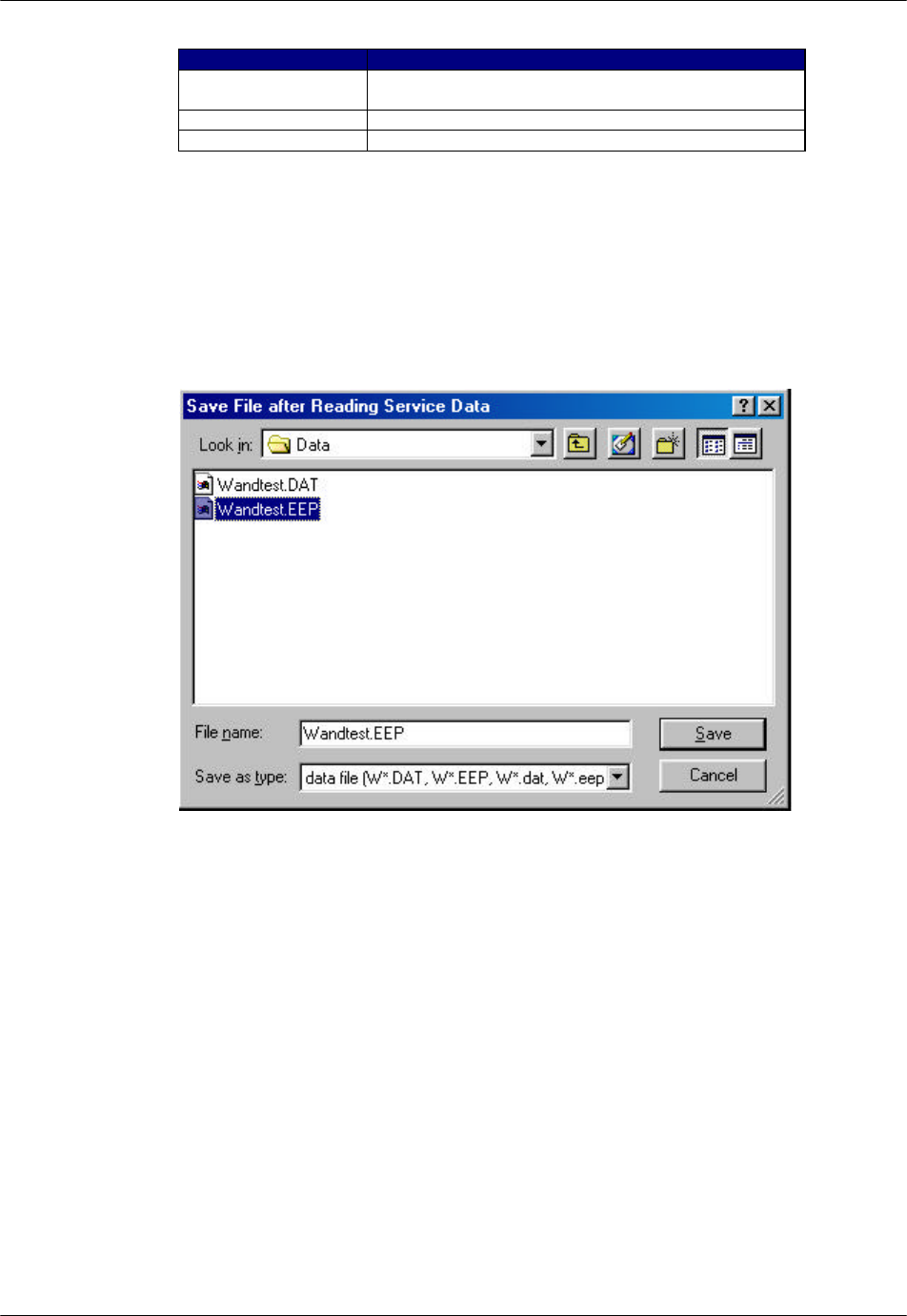
3. The following window appears, prompting for the folder and file name in
which to save the service data after reading out.
Figure 4-49: Save File after Reading Service Data Window
4. Select a folder and enter a file name. The file name must have the extension
of .dat or .eep. In addition, the file name must start with W and have 8
letters. Then click Save.
5. A confirmation box appears. Click Yes to start the reading of the data.
4.3.6 Write Data
Use the procedure in this section to load the operation data to both the SDMs
while the RPC is operating. As for this command, automatic switching is not
supported. After the implementation of the command, the RPC still runs based on
RPC/RP Manual RPC/RP Configuration
19June2000 WLL-RPC/RP-IN/UM-1.0
4-
45
the old loaded operation data. For the RPC to run based on the newly loaded
operation data, the RPC needs to be reset.
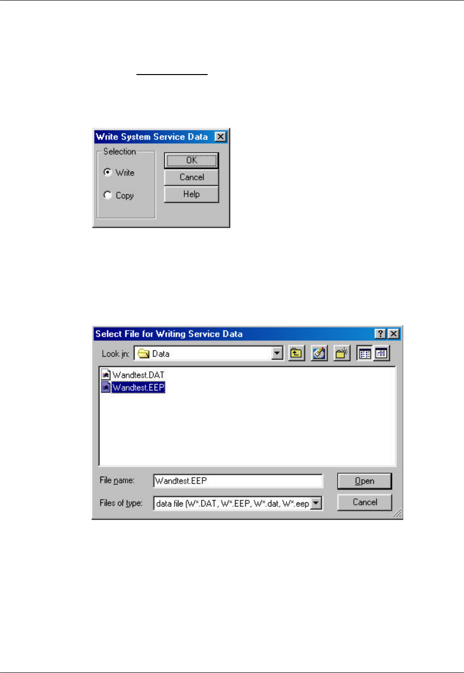
1. From the Configuration main menu, click Service Data, and then Write
Data. This opens the Write System Service Data window, as shown in the
figure below.
Figure 4-50: Write System Service Data Window
2. Click the Write radio button and then click OK. The Select File for Writing
Service Data window appears, as illustrated in the figure below.
Figure 4-51: Select File for Writing Service Data Window
3. Select the target file with either a .dat or a .eep extension and click Open.
The system overwrites the service data on both the SDMs of the RPC.