UTStarcom Korea Technologies UTS-EA7H75B Wireless Local Loop Fixed Terminal User Manual Cover
UTStarcom Korea Technologies Ltd. Wireless Local Loop Fixed Terminal Cover
Contents
Manual 1
Wireless Local Loop
RPC/RP Installation &
Configuration Manual
WLL-RPC/RP-IN/UM-1.0
June 19, 2000

RPC/RP Manual
WLL-RPC/RP-IN/UM-1.0 19June2000
ii
Compiled by (Joseph) Guangping Zhang
Copyright 2000 UTStarcom Inc. All Rights Reserved.
This manual has been prepared for UTStarcom customers, UTStarcom personnel,
and licensees. The information contained herein is the property of UTStarcom
Inc. and shall be neither reproduced nor utilized in any form or by any means,
electronically or mechanically, in whole or in part, without prior written approval
from UTStarcom Inc.

RPC/RP Manual
19June2000 WLL-RPC/RP-IN/UM-1.0
iii
Important Safety Instructions !
Safety Information:
Installer and User WARNING
The device is to be installed and operated at a “fixed location”. The term
"fixed location" means that the device is physically secured at one location
and is not able to be easily moved to another location.
It must be located - (for indoor RPs) up on or near the ceiling away from
users or bystanders – (for outdoor RPs) on the roof top site, pole, building, or
traffic light away from users or bystanders. It must be mounted in a manner
to ensure that a minimum separation distance of 20cm is normally
maintained between all users, bystanders and the antenna (including any
radiating structure).
The installer may be required to perform an MPE evaluation and an
Environmental Assessment (EA) of the location at the time of licensing per
CFR 47 Part 1.1307. Fixed mounted antennae that are co-located with other
antennae must satisfy the co-location requirements of Part 1.1307.
Limits:
The limit for general population/uncontrolled environment exposures is 1
2
/cmmW for the band 1500-100,000 MHz.
MPE evaluation:
The following calculations are provided for the more restrictive limit:
uncontrolled environment/general population.
The calculated minimum safe distance, Radii(cm), is approximately 10 times
lower than the minimum required installation distance of 20 cm per Part 2.1091.
RPC/RP Manual
WLL-RPC/RP-IN/UM-1.0 19June2000
iv
Therefore, the transmitter model numbers EA7H74B and EA7H75B complies
with the MPE requirements by providing a safe separation distance between the
antenna (including any radiating structure) and any persons.
The calculations were performed using formulas found in OET Bulletin 65
Edition 97-01(1997).
Transmitter Specifications:
Antenna
Type Gain (dBi) Output
power EIRP
(dBm)
Output Power
(dBm) Base
stations M/N Minimum
Installation
Distance
(cm)
2.4 21.4 19 dBm (Peak) EA7H74B 20 Built-in 2.4 12.4 10 dBm (avg) EA7H74B 20
7 26 19 dBm(Peak) EA1H75B 20 Omni-
Directional 7 17 10 dBm (avg) EA1H75B 20
MPE Radii (m) For general population/uncontrolled environment
Power P(W) Max. Peak Antenna G numeric Radii(cm)
Base stations M/N
0.08 1.7 1.5 EA7H74B
0.08 5.0 2.5 EA1H75B
General Safety Instructions:
• The sign on the top right corner is intended to alert the user the presence of
important operation and maintenance (service) instructions in the literature
accompanying the product. Also notice warnings such as “WARNING!” or
“CAUTION.”
• When installing, operating, or maintaining the system, please follow the basic
safety procedures in order to reduce the risk of fire, electric shock, and injury to
persons, as listed below:
• Read and understand all instructions.
• Follow all warnings and instructions marked on this product.
• For information on proper mounting instructions, consult the Installation Manual
provided with this product.
• Install only equipment identified in the Installation Manual provided with this
product. Use of other equipment may result in improper connection of circuitry
leading to fire or injury to persons.

RPC/RP Manual
19June2000 WLL-RPC/RP-IN/UM-1.0
v
• The telecommunication interfaces should not leave the building unless connected
to telecommunication devices providing primary and secondary protection, as
applicable.
• This product should only be operated from the type of power source indicated on
the marking label.
• This equipment must be provided with a readily accessible disconnect device as
part of the building installation.
• Installation must include an independent frame ground drop to building ground.
Refer to installation instructions.
• Do not use this product near water, for example in a wet basement.
• Do not place this product on an unstable cart, stand, or table. The product may
fall, causing serious damage to the product.
• Use caution when installing or modifying telecommunications lines.
• Never install telecommunications wiring during a lightning storm.
• Never install telecommunications in wet locations.
• Never touch uninsulated telecommunications wires or terminals unless the
telecommunications line has been disconnected at the network interface.
• Never touch uninsulated telecommunications wires or terminals carrying direct
current or ringing current or leave this wiring exposed. Protect and tape such
wiring and terminals to avoid risk of fire, electric shock, and injury to service
personnel.
• Never push objects of any kind into this product through slots as they may touch
dangerous voltage points or short-out parts that could result in a risk of fire or
electrical shock. Never spill liquids of any kind on this product.
• Slots and openings in the unit are provided for ventilation, to protect it from
overheating. These openings must not be blocked or covered. This product
should not be placed in a built-in installation unless proper ventilation is provided.
• To reduce the risk of an electrical shock, do not disassemble this product. Service
should be performed by trained personnel only. Opening or removing covers
and/or circuit boards may expose you to dangerous voltages or other risks.
Incorrect re-assembly can cause electrical shock when the unit is subsequently
used.

RPC/RP Manual
WLL-RPC/RP-IN/UM-1.0 19June2000
vi
• This equipment is intended for installation in restricted access locations where
access is controlled or where access can only be gained by service personnel with
a key or tool. Access to this equipment is restricted to qualified service personnel.
Save These Instructions!

RPC/RP Manual
19June2000 WLL-RPC/RP-IN/UM-1.0
vii
Table of Contents
1 INTRODUCTION ...................................................................................................................................................1-1
1.1 PURPOSE...................................................................................................................................................................1-1
1.2 ORGANIZATION ........................................................................................................................................................1-1
1.3 DOCUMENTATION CONVENTIONS ...........................................................................................................................1-2
2 RPC INSTALLATION................................................................................................................................................2-1
2.1 GENERAL DESCRIPTION...........................................................................................................................................2-1
2.1.1 Main RPC Features.........................................................................................................................................2-2
2.1.2 RPC Module Descriptions...............................................................................................................................2-3
2.1.2.1 Enhanced Control Module ..............................................................................................................................2-4
2.1.2.2 E1 Interface Module .......................................................................................................................................2-5
2.1.2.3 Radio Port Interface Module ...........................................................................................................................2-7
2.1.2.4 Application Software Loading Module ............................................................................................................2-9
2.1.2.5 ADPCM Highway........................................................................................................................................2-10
2.2 SYSTEM CONSTRUCT ION ...................................................................................................................................... 2-10
2.3 INSTALLATION....................................................................................................................................................... 2-12
2.3.1 Before Beginning........................................................................................................................................... 2-12
2.3.2 RPC Site Selection......................................................................................................................................... 2-12
2.3.3 Tools Required.............................................................................................................................................. 2-13
2.3.4 Installation Instructions................................................................................................................................ 2-13
3 RP INSTALLATION...................................................................................................................................................3-1
3.1 GENERAL DESCRIPTION...........................................................................................................................................3-1
3.1.1 Traffic Handling...............................................................................................................................................3-3
3.1.2 Cell Overlap .....................................................................................................................................................3-5
3.1.3 Air Interface Handling.....................................................................................................................................3-6
3.2 SYSTEM CONSTRUCTION .........................................................................................................................................3-8
3.3 INDOOR RP INSTALLATION INSTRUCTIONS ......................................................................................................... 3-10
3.3.1 Before Beginning........................................................................................................................................... 3-10
3.3.2 Site Selection................................................................................................................................................. 3-11
3.3.3 Indoor RP Installation .................................................................................................................................. 3-11
3.4 OUTDOOR RP INSTALLATION INSTRUCTIONS...................................................................................................... 3-13
3.4.1 Before Beginning........................................................................................................................................... 3-14
3.4.2 Outdoor RP Installation................................................................................................................................ 3-14
4 RPC/RP CONFIGURATION.....................................................................................................................................4-1
4.1 INITIALIZE AN RPC NODE.......................................................................................................................................4-1
4.1.1 Background Map..............................................................................................................................................4-5
4.1.2 Add RPC Icons on the Map .............................................................................................................................4-7
4.1.3 Add RP Icons....................................................................................................................................................4-9
4.2 RPC CONFIGURATION .......................................................................................................................................... 4-11
4.2.1 Set Time.......................................................................................................................................................... 4-12
4.2.2 RPC Change.................................................................................................................................................. 4-13
4.2.3 Unit Control................................................................................................................................................... 4-13
4.2.3.1 Blockade/Unblockade...................................................................................................................................4-14
4.2.3.2 TimeSlot Layout ..........................................................................................................................................4-16
4.2.3.3 Maintenance.................................................................................................................................................4-17
4.2.3.4 Change Master RP........................................................................................................................................4-18
4.2.3.5 RPC Synchronization ...................................................................................................................................4-18
4.2.3.6 Online Trace................................................................................................................................................4-20
4.2.4 Function Status.............................................................................................................................................. 4-21

RPC/RP Manual
WLL-RPC/RP-IN/UM-1.0 19June2000
viii
4.2.4.1 RPC Status...................................................................................................................................................4-22
4.2.4.2 RP Status .....................................................................................................................................................4-23
4.2.4.3 RP-I/F Board Status .....................................................................................................................................4-28
4.2.4.4 E1 Signal Status ...........................................................................................................................................4-29
4.2.4.5 E1 Interface Status .......................................................................................................................................4-30
4.2.4.6 Air Channel Status .......................................................................................................................................4-31
4.2.4.7 Time Slot Status ...........................................................................................................................................4-32
4.2.5 Self Messages................................................................................................................................................. 4-33
4.2.6 Reset RPC...................................................................................................................................................... 4-34
4.2.7 Antenna Information..................................................................................................................................... 4-36
4.2.8 RPC Connection............................................................................................................................................ 4-37
4.2.9 Version Window............................................................................................................................................ 4-37
4.3 MANAGE RPC DATA ............................................................................................................................................ 4-38
4.3.1 Program Load ............................................................................................................................................... 4-38
4.3.2 Program Switch............................................................................................................................................. 4-40
4.3.3 Data Load...................................................................................................................................................... 4-41
4.3.4 Data Switch.................................................................................................................................................... 4-42
4.3.5 Read Data...................................................................................................................................................... 4-43
4.3.6 Write Data ..................................................................................................................................................... 4-44
4.3.7 Copy Data...................................................................................................................................................... 4-46
4.3.8 Edit Data........................................................................................................................................................ 4-46
4.3.8.1 Service Data 1: RP Installation .....................................................................................................................4-47
4.3.8.2 Service Data 2: Group Control Configuration................................................................................................4-48
4.3.8.3 Service Data 3: System Parameters...............................................................................................................4-50
4.3.9 Change Data (RP Installation)..................................................................................................................... 4-58
4.3.10 Change Data (E1-IF Board Installation).................................................................................................. 4-60
4.3.11 Change Data (Data Value)......................................................................................................................... 4-61
4.4 MANAGE RPC ALARMS........................................................................................................................................ 4-62
4.4.1 Warning Status.............................................................................................................................................. 4-62
4.4.2 Alarm History................................................................................................................................................ 4-63
4.5 RESET RPC............................................................................................................................................................ 4-64
4.6 RPC STATISTICS ................................................................................................................................................... 4-67
4.6.1 RPC Traffic Report....................................................................................................................................... 4-67
4.6.2 RPC Outstanding Alarms ............................................................................................................................. 4-69
4.6.3 RP Status Report ........................................................................................................................................... 4-70
A SPECIFICATIONS ...................................................................................................................................................A-1
A.1 RPC SPECIFICATIONS ............................................................................................................................................A-1
A.1.1 Champ Connector Pin Assignments..............................................................................................................A-2
A.2 RP SPECIFICATIONS ...............................................................................................................................................A-4
A.2.1 Radio Features................................................................................................................................................A-4
A.2.2 Outdoor Type RP............................................................................................................................................A-4
A.2.2.1 Antenna .......................................................................................................................................................A-5
A.2.3 Indoor Type RP...............................................................................................................................................A-5
B GLOSSARY.................................................................................................................................................................B-1
C EDITOR’S NOTE ......................................................................................................................................................C-1
C.1 NOTICE TO CUSTOMERS ...................................................................................................................................C-1
C.2 HOW TO COMMENT ON THIS DOCUMENT ........................................................................................................C-3
C.3 FEEDBACK FORM ..............................................................................................................................................C-5

RPC/RP Manual
19June2000 WLL-RPC/RP-IN/UM-1.0
ix

RPC/RP Manual
WLL-RPC/RP-IN/UM-1.0 19June2000
x

19June2000 WLL-RPC/RP-IN/UM-1.0
1
Introduction
1 Introduction
1.1 Purpose
This manual describes the installation and configuration procedures for the Radio
Port Controller (RPC) and Radio Port (RP). It is intended for the following
customer personnel who participate in the engineering, installation, operations,
and maintenance of the system.
• Equipment Engineers and outside plant engineers
• Installation, Operation, and Maintenance Personnel
• System Administrators
• Training Personnel
1.2 Organization
Listed below is the brief description of each chapter in this manual:
Introduction - Describes the contents of this manual and the conventions used.
RPC Installation - Details the steps necessary to install the Radio Port Controller.
RP Installation - Represents the procedures to install the Radio Port.
RPC/RP Configuration - Explains the configuration process for both the RPC and
the RP.
Appendix A: Specifications – Describes the RPC/RP specifications and Champ
connector pin assignments.
Appendix B: Glossary – Lists the meaning of the acronyms used in this manual.
Appendix C: Editor’s Note – Provides the notice to the customers, customer
service office addresses, and feedback form.

Introduction RPC/RP Manual
WLL-RPC/RP-IN/UM-1.0 19June2000
1-
2
1.3 Documentation Conventions
Certain conventions are used in this document to denote types of information,
such as commands, screen titles, options, and so on. The table below defines
these conventions.
Style Used For: Example
Italics Cited titles of books, chapters, and
sections in the literature Performance Management
Bold Window and dialog box names, icon
names, and field names Netman Database Window
Bold andUnderlined Menu names Configuration
Bold and Italics Menu options, command, and button
names Configure DLC
F followed by
italic text
Notes, cautions, and warnings F NOTE: This feature
does not apply to RPC nodes.
Initial Capital Letters Names of functions, window tabs,
and directory and file names Double click the E1 Port Index
field.
<Angled Brackets
with Bold and
Italicized Contents>
Variable sytem output The status displayed is COMM
<DLC#>
Table 1-1: Documentation Conventions

RPC/RP Manual Introduction
19June2000 WLL-RPC/RP-IN/UM-1.0
1-
3

19June2000 WLL-RPC/RP-IN/UM-1.0
2
RPC Installation
2 RPC Installation
2.1 General Description
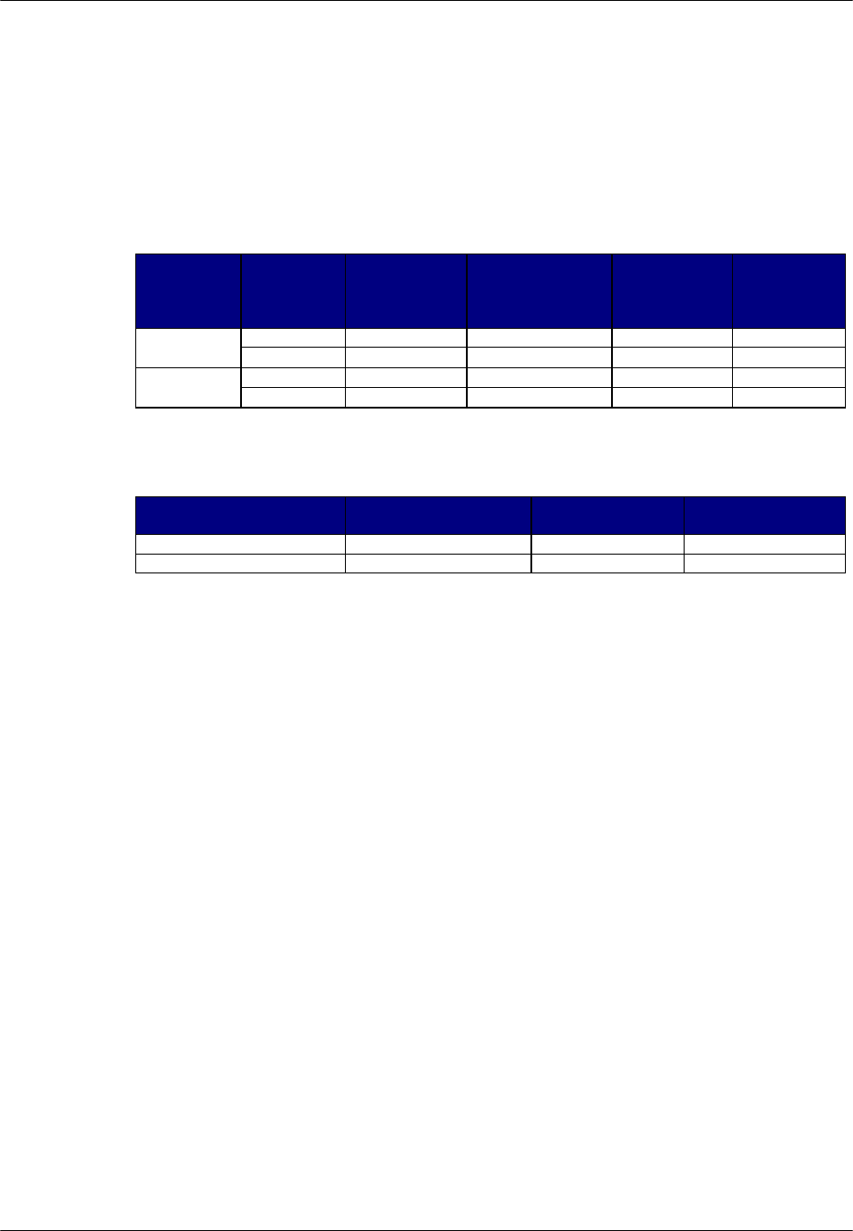
The Radio Port Controller (RPC) functions as the controller and power distributor
for the Radio Ports (RPs). It is also the concentrator of the speech paths and the
protocol converter for the PHS protocol and the Q.931 protocol. It has Dual Tone
Multi Frequency (DTMF) senders for dialing to the Local Exchange (LE) through
the Central Office Terminal (COT). In addition, the RPC synchronizes the
associated RPs by extracting the synchronous clock from the E1 line connected to
the COT and distributing it to all of the associated RPs.
RPCs can be co-located with a COT or located remotely and communicate with
the COT using E1 transmission over:
• High Density Subscriber Loop (HDSL)
• Fiber Optic Transmission (FOT)
• Digital microwave radio
Figure 2-1 presents an overview of the RPC and RPs in the WLL system.
RPC Installation RPC/RP Manual
WLL-RPC/RP-IN/UM-1.0 19June2000
2-
2
Figure 2-1: RPC in the WLL System
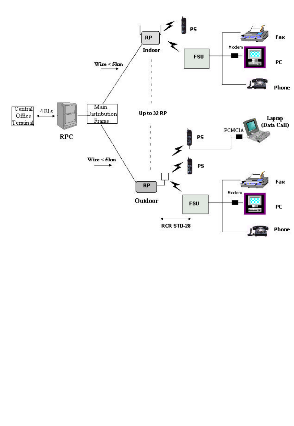
2.1.1 Main RPC Features
An RPC consists mainly of four types of function modules:
• One ECNT (Enhanced Control) module
• Up to four E1IF (E1 Interface) modules
• Up to eight RPIF (RP Interface) modules
• One APL (Application Software Loading) module - Optional
Figure 2-2 displays the four types of the function modules in the RPC.
RPC/RP Manual RPC Installation
19June2000 WLL-RPC/RP-IN/UM-1.0
2-
3
Figure 2-2: Function Modules inside the RPC
Each RPC can handle traffic loads of up to 120 simultaneous telephone calls.
Four E1 trunks connect to the COT side and support 30 subscriber channels each.
In normal traffic conditions, a single RPC can service approximately 1000
subscribers.
The RPC is monitored and controlled from the network management system
connected to the COT. With this setup the program data, the operation data, and
the system parameters can be changed and the alarm information and traffic data
can be gathered easily.
2.1.2 RPC Module Descriptions
The following sections describe the RPC component modules, including the
physical configuration, Light Emitting Diodes (LEDs), and switch operations.

RPC Installation RPC/RP Manual
WLL-RPC/RP-IN/UM-1.0 19June2000
2-
4
2.1.2.1 Enhanced Control Module
The ECNT module provides the Operation, Administration and Maintenance
(OA&M) support for the RPC. In addition, it provides the time slot cross connect
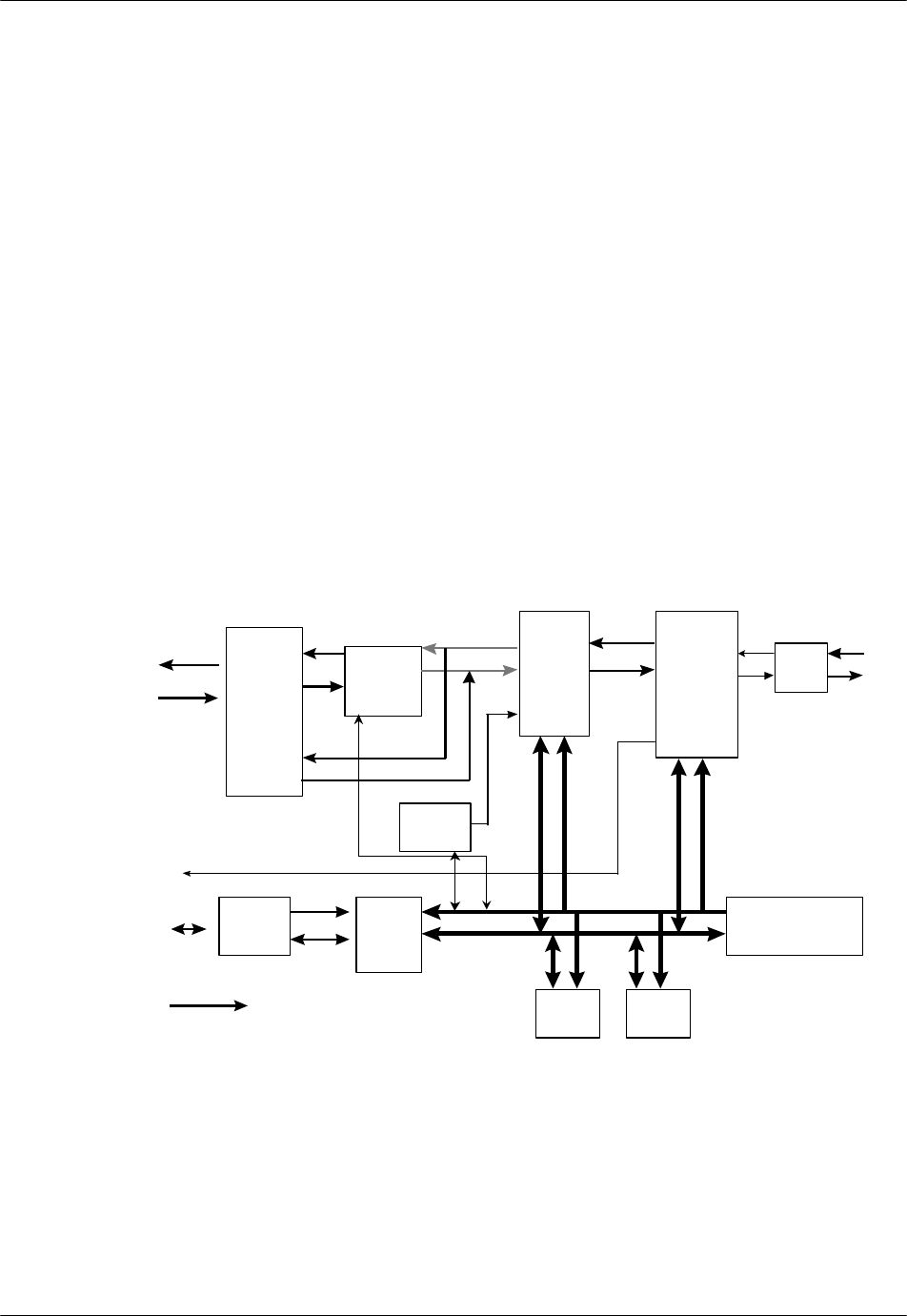
switch for communications between the E1IFs and the RPIFs. Figure 2-3
represents the ECNT functions.
Figure 2-3: ECNT Block Diagram
The ECNT module performs the clock synchronization by generating a
synchronized clock from the extracted clock signal from the E1 line on the E1
interface card and delivers it to the RP lines on the RP interface cards.
The RPC uses a control bus via the ADPCM highway on the mother board to
synchronize the system. The Control Bus is an 8-bit mixed bus address with data
and First-in First-out (FIFO) type bus. The main CPU on the ECNT card, the
local CPUs on E1 Interface cards and the RP-interface cards are all connected by
this bus. The main CPU on the ECNT card controls the bus.
RPC/RP Manual RPC Installation
19June2000 WLL-RPC/RP-IN/UM-1.0
2-
5
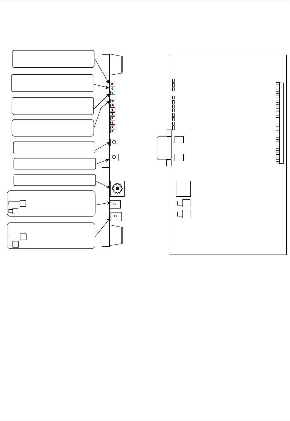
Figure 2-4 shows the module’s physical configuration and describes the function
of the LEDs and the reset switch.
System Reset Switch :
=Reset system
=Normal operations
ALM : Red =fault detected on this
module
RUN : Green=normal operations
SYNC : Green=E1 interface circuit
established Layers 1 and 3
LEDs 0 through 7 : Red=Frame
Rotary Switch (U) : Setting=0
Rotary Switch (L) : Setting=2
7
6
5
4
3
2
1
0
RMT or PC Connector
Alarm Reset Switch :
=Reset alarms
=Normal operations
Figure 2-4: ECNT Module Layout
2.1.2.2 E1 Interface Module
The RPC connects to the COT through a 2.048 Mbps E1 Interface that carries all
the control and voice channels, that is, PCM encoded voice or voice band data,
between the COT and the RPC. The E1 Interface (E1IF) module communicates
externally with the COT through 1 G.703 E1 interface and uses Q.931 non-facility
associated signaling protocol.
Transmission between the RPC and RP is based on a proprietary, echo-canceled
transmission standard, which is similar to the recognized G.961 ISDN standard.
The E1IF provides the speech coding conversion between A-law PCM from the
COT and Adaptive Differential Pulse Code Modulation (ADPCM), which is ITU-
RPC Installation RPC/RP Manual
WLL-RPC/RP-IN/UM-1.0 19June2000
2-
6
Rec.726 compliant, from the RP. It supports 32 kbps channel signaling for
encoded voice and voice band data calls.
In addition, the E1IF communicates internally with the Radio Port Interface
(RPIF) module for interfacing RPs through the backplane busses and the switch in
the ECNT module.
The E1IF module is an E1 module (E1M) that provides 4 E1 connections to the
E1 network. The E1 module has the following functions:
• Originates/terminates 4 G.703/G.704 2.048 Mbps E1 interface
• Provides 75 ohm unbalanced interface
• Provides LEDs for module and port status and alarms
• Performs CRC-4 on the E1 line according to G.706
• Monitors performance of each E1 line
• Detects errors and alarms on the E1 lines.
Figure 2-5 depicts the processing of the E1IF module
Highway
Exchanger
ADPCM
CODEC
Loudness
Controller
ADPCM
Highway
E1 IF
LSI LIF
A-law PCM Highway A-law PCM
Highway E1 to
COT
Bus
Controller DPRAM CPU
(16 bit)
DTMF
Sender
Reference
Clock
+5 V
Internal
Bus
RAM ROM
Address Bus
Data Bus
Figure 2-5: E1 Interface (E1IF) Module Block Diagram
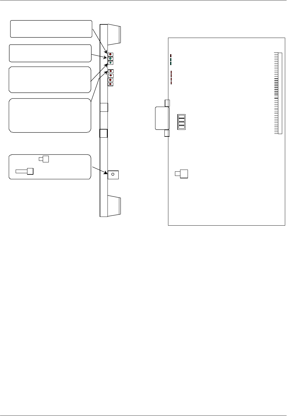
Figure 2-6 shows the module’s physical configuration and describes the function
of the LEDs and the reset switch.

RPC/RP Manual RPC Installation
19June2000 WLL-RPC/RP-IN/UM-1.0
2-
7
ALM : Red =fault detected on this
module
RUN : Green=normal operations
CHM : Green=E1 interface circuit
has established Layers 1 and 3
FSYC : Red=Frame out of
synchronization is dectected
LOS : Red=loss of signal is
dectected
AIS : Red=Alarm indication signal
is detected
RAI : Red=RAI signal is detected
RST Switch : =Resets the entire
interface module
= Normal operations
Figure 2-6: E1IF Module Layout
2.1.2.3 Radio Port Interface Module
Each RPC controls and feeds a maximum of 32 RPs. The RPC connects to the
RPs through a 2-wire proprietary interface. Line power feeding from the RPC
provides a power source of 116V DC to the RPs.
The RPC controls the RPs via 8 RPIF modules. Each RPIF module provides an
ISDN Basic Rate interface to 4 RPs. The RP is extended from the RPC to a
maximum distance of 5.0km using a pair of φ0.5 wires and approximately 3.5 km
using a pair of φ0.4 wires.
The Radio Port Interface (RPIF) module communicates externally with four RPs
through ISDN Basic Rate Interfaces (BRI). In addition, it communicates

RPC Installation RPC/RP Manual
WLL-RPC/RP-IN/UM-1.0 19June2000
2-
8
internally with the E1IF through the backplane busses and the switch in the ECNT
module. Refer to Figure 2-7 for a block diagram of the RPIF module’s
processing.
RPIF
RPIF
RPIF
RPIF
Layer 1
LSI
Layer 1
LSI
Layer 1
LSI
Layer 1
LSI
-116V
+5V
Time slot
Assignment
Controller
HDLC
Controller
CPU
(16 bit)
Bus
Controller
DPRAM
RAM
ROM
Address Bus
Data Bus
ADPCM Highway
ADPCM Highway
PCM
Clock/ Frame
signal
Generator
ADPCM Clock
Internal
BUS
Figure 2-7: RPIF Module Block Diagram
Figure 2-8 shows the module’s physical configuration and describes the function
of the LEDs and the reset switch.
RPC/RP Manual RPC Installation
19June2000 WLL-RPC/RP-IN/UM-1.0
2-
9
ALM : Red =fault detected on this
module
RUN : Green=normal operations
SUS: Green=one or more Rps
operational
Not Lit=operations suspended
on all connected RPs
RP1 through RP4 :
Green=normal operations
Red=RP not connected, is faulty or
is blocked
RST Switch : =Resets the entire
interface module
= Normal operations
Distance
Switch
Short
Long
Figure 2-8: RPIF Module Layout
2.1.2.4 Application Software Loading Module
The Application Software Loading (APL) Module facilitates the downloading of
software in the event there is a problem in loading software. It permits the
upgrading of the ECNT module firmware. In addition, any software upgrades can
be downloaded remotely from a PC to an RPC. The APL module is installed only
when the software or firmware needs to be upgraded or downloaded. It is not
intended to remain in the system during the normal operations.
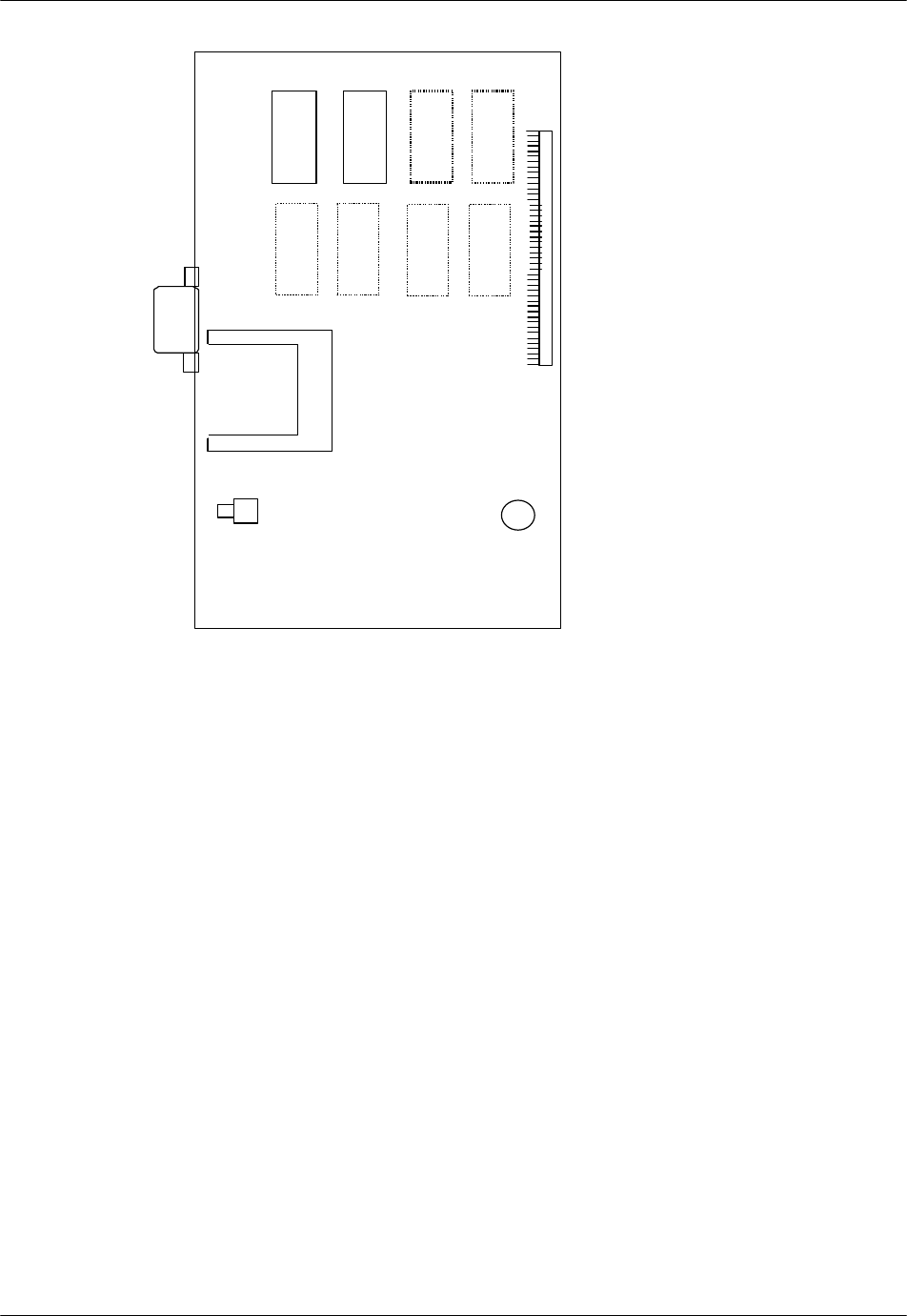
Figure 2-9 demonstrates the module’s physical configuration:
RPC Installation RPC/RP Manual
WLL-RPC/RP-IN/UM-1.0 19June2000
2-
10
Figure 2-9: Application Module Layout
2.1.2.5 ADPCM Highway
The ADPCM (Adaptive Differential Pulse Code Modulation) highway is the
synchronous time multiplex digital voice/data path, and consists of up-stream and
down-stream for Time Switch on the ECNT card. Time Switch and the digital
voice and data paths on the E1IF cards and the RPIF cards are connected by the
ADPCM highway.
There are 8 ADPCM highways in an RPC. Half of them are assigned for E1IF
cards, and the rest are assigned for RPIF cards. The bit rate of an ADPCM
highway is 2048 kbps, and the frame repetition rate is 8 kHz.
2.2 System Construction
An RPC has two types of installation scenarios:
• Rack mount
• Stand-alone
RPC/RP Manual RPC Installation
19June2000 WLL-RPC/RP-IN/UM-1.0
2-
11
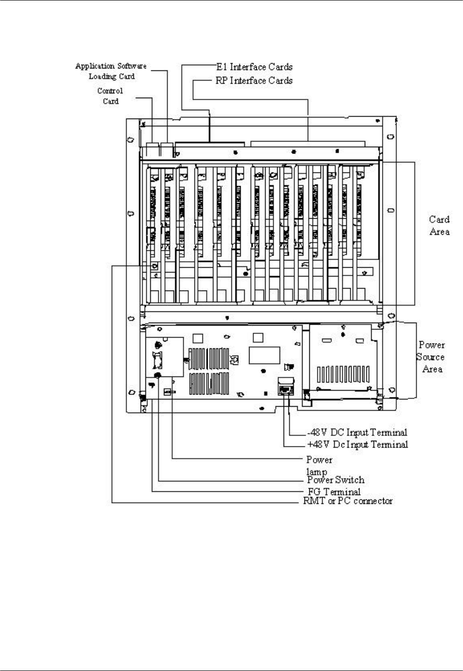
Figure 2-10 shows the physical configuration of the rack mount type RPC.
Figure 2-10: Layout of Rack Mount Type RPC
The RPC is 532.6mm high, 482.6mm wide, and 265mm deep.
RPC Installation RPC/RP Manual
WLL-RPC/RP-IN/UM-1.0 19June2000
2-
12
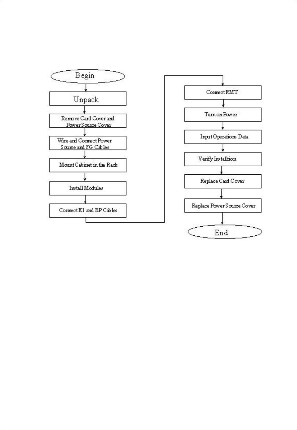
2.3 Installation
This section provides the instructions for installing an RPC. The flow chart in
Figure 2-11 depicts the steps involved in the installation.
Figure 2-11: RPC Installation Flow Chart
2.3.1 Before Beginning
To ensure that the RPC installation goes smoothly, it is necessary to do adequate
planning prior to the installation, including:
• Location of the RPC
• Tools required
• Number of people needed to complete an installation.
2.3.2 RPC Site Selection
The RPC needs an environment that is relatively dust and moisture free. Make
sure the location meets the following requirements:

RPC/RP Manual RPC Installation
19June2000 WLL-RPC/RP-IN/UM-1.0
2-
13
• Not in direct sunlight
• Free from extremes of heat, cold, and moisture
• 0° to 40° C ambient temperature
2.3.3 Tools Required
Be sure to have the following necessary tools:
• Screwdrivers
• Soldering iron and solder
• Tie bands for cabling
2.3.4 Installation Instructions
Follow the steps below to install the RPC:
1. Carefully unpack the RPC and the accessories and make sure that they are in
good condition. Accessories include 2 connectors for the RP connection
cables. Refer to Figure 2-12 for unpacking.

RPC Installation RPC/RP Manual
WLL-RPC/RP-IN/UM-1.0 19June2000
2-
14
Figure 2-12: Unpacking the RPC and Accessories
2. Before installing the RPC in the rack, make sure to remove the card cover and
the power source cover.
F CAUTION: Do not take a photo with a flash once the card cover has been
removed. RPC may not operate.
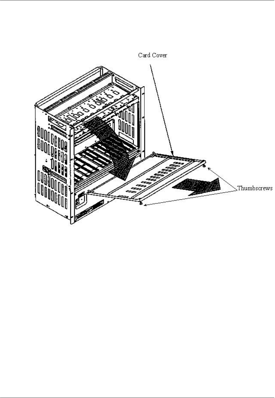
3. Loosen the thumbscrews. Tilt open the cover and slide it out as shown in
Figure 2-13.
RPC/RP Manual RPC Installation
19June2000 WLL-RPC/RP-IN/UM-1.0
2-
15
F CAUTION: The card cover cannot hold itself when opened. Be sure to detach it
from the cabinet.
Figure 2-13: Removal of the Card Cover
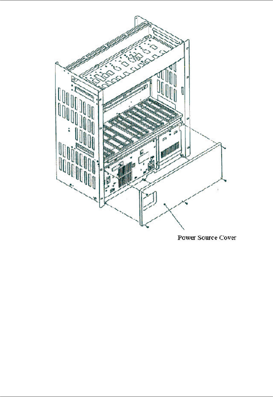
4. Remove the 5 M3 screws in the power source cover and remove it, as
illustrated in Figure 2-14.
RPC Installation RPC/RP Manual
WLL-RPC/RP-IN/UM-1.0 19June2000
2-
16
Figure 2-14: Removal of the Power Source Cover
F CAUTION: When inserting and removing each component, make sure to follow
the proper electro-static discharge (ESD) procedures.
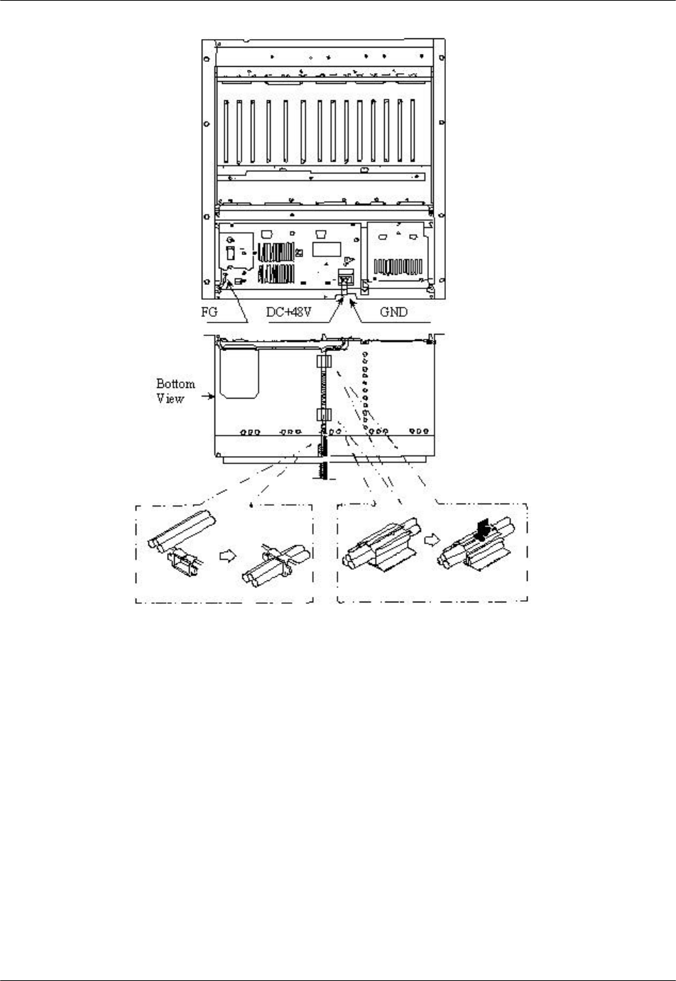
5. Connect and wire the power source and FG cables, as shown in the figure
below.
RPC/RP Manual RPC Installation
19June2000 WLL-RPC/RP-IN/UM-1.0
2-
17
Figure 2-15: Power and FG Cable Connectors
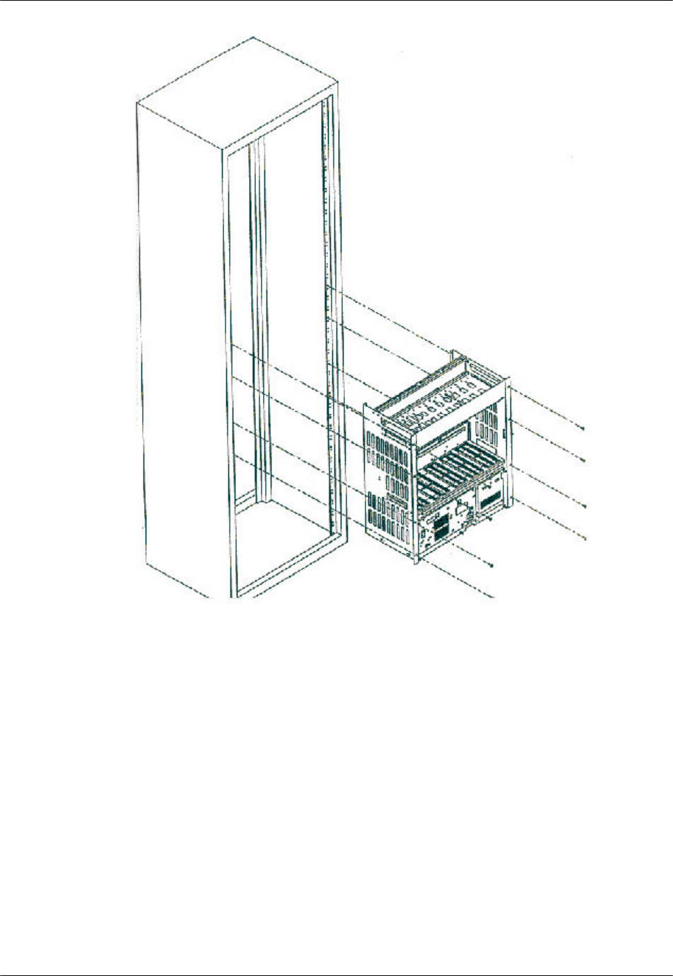
6. Insert the RPC in the rack and fasten to the rack with 8 screws as indicated in
Figure 2-16.
F CAUTION: Make sure the RPC is firmly mounted in the rack. Serious injury
could occur if the RPC fell out of the rack.
RPC Installation RPC/RP Manual
WLL-RPC/RP-IN/UM-1.0 19June2000
2-
18
Figure 2-16: Mounting the RPC in the Rack
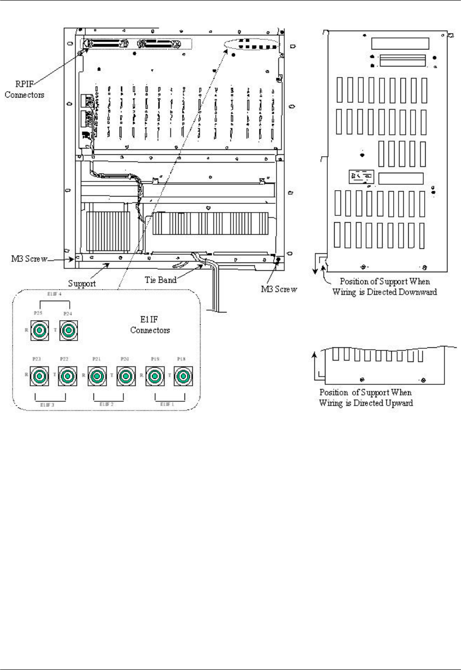
7. After installing the RPC in the rack, affix the wiring as indication in Figure
2-17. Redirect the support according to the direction of the wiring, as shown
in Figure 2-17.
RPC/RP Manual RPC Installation
19June2000 WLL-RPC/RP-IN/UM-1.0
2-
19
Figure 2-17: Wiring – Back of RPC
8. Connect the coaxial cable with an SMB coaxial cable plug having an
impedance of 75 ohms into the E1IF connectors on the back of the RPC, as
shown in Figure 2-17
9. Connect the cable with a Champ plug to the RPIF connector on the back of
the RPC. Refer to Figure 2-17. Table 2-1 provides the maximum cable
lengths between the RPC and the RP for 2 different wire gauges. Refer to
Appendix A for the description of the 2 Champ RPIF connector pin
assignments.
RPC Installation RPC/RP Manual
WLL-RPC/RP-IN/UM-1.0 19June2000
2-
20
Wire Guage Maximum Cable Length
φ0.4 m 3.5Km
φ0.5 m 5.0Km
Table 2-1: Maximum RP Cable Length
F NOTE: Be sure to use a twisted pair cable or a 2 pair twisted cable. Avoid any 2
pair twisted cable splits before connecting cables.
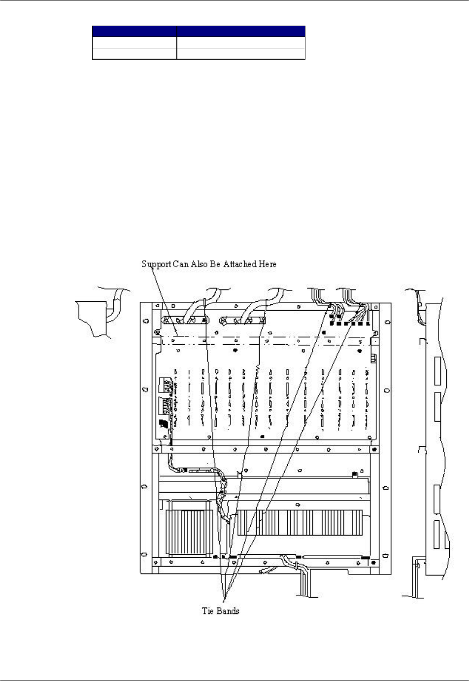
10. When the RP and E1 cables are connected, attach the cabling to the supports
with tie bands. Refer to Figure 2-18.
F NOTE: Tie Bands are to be prepared on-site.
Figure 2-18: Cabling Example

RPC/RP Manual RPC Installation
19June2000 WLL-RPC/RP-IN/UM-1.0
2-
21
11. Install the modules in the RPC slots according to the labels on the cabinet.
Refer to Figure 2-19 for the slot assignment.
F NOTE: The APL module is installed only when the software upgrades are
unsuccessful without it. It is not intended to remain in the system during normal
operations.
Figure 2-19: RPC Slot Assignment
12. Make sure that the rotary switches on the ECNT module are correctly set
before applying power. The correct switch settings are shown in Table 2-2.

RPC Installation RPC/RP Manual
WLL-RPC/RP-IN/UM-1.0 19June2000
2-
22
Switch Name Setting
Rotary Switch (U):S4 0
Rotary Switch (L):S5 2
Table 2-2: Rotary Switch Settings
13. Slide the card into the RPC shelf using the upper and lower slot guides. When
properly seated, the lower edge of the card is recessed from the outer edge of
the lower slot guide. And the upper edge of the card is flush with the outer
edge of the upper card guide. Refer to Figure 2-20.