UTStarcom Telecom 1023 Wireless AP User Manual
UTStarcom Telecom Co., Ltd. Wireless AP Users Manual
UserManual.wiki
>
UTStarcom Telecom
>
1023 User Manual
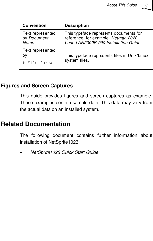
Users Manual
Navigation menu
Upload a User Manual
Namespaces
Wiki Guide
HTML
PDF
Info
Views
User Manual
Discussion / Help
Navigation
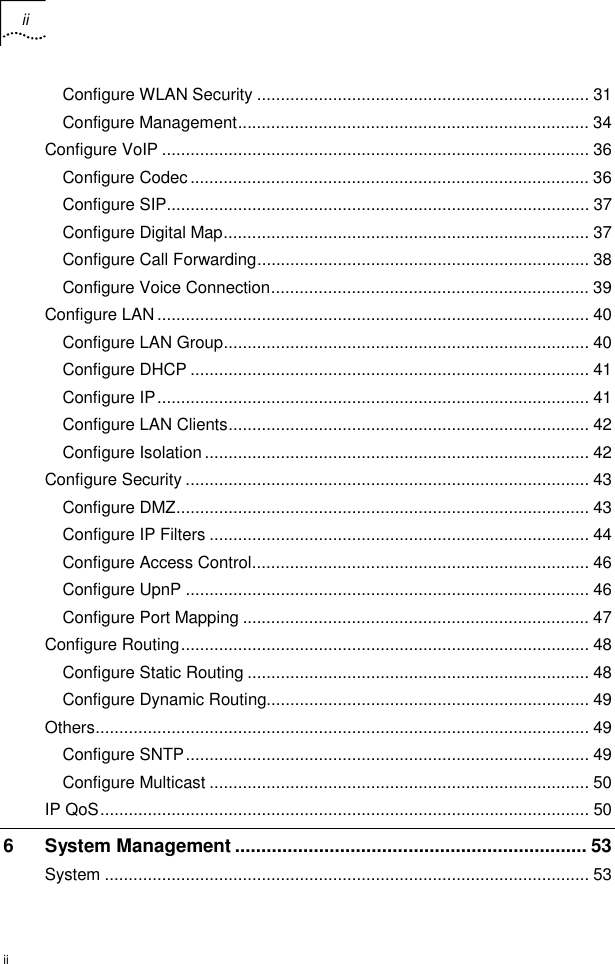

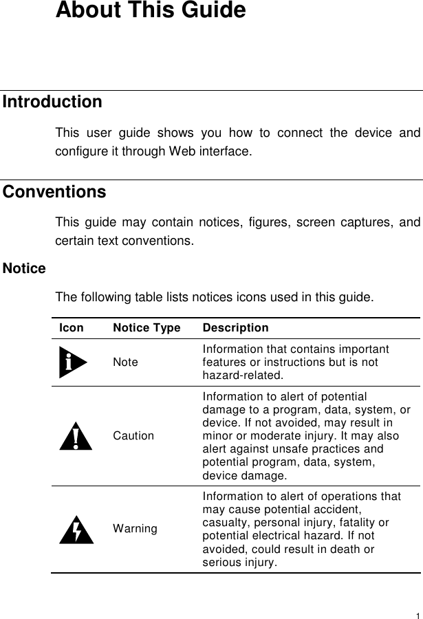
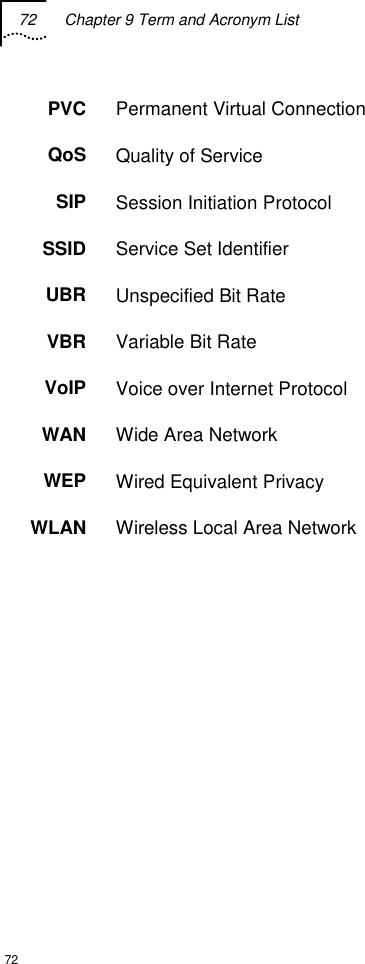
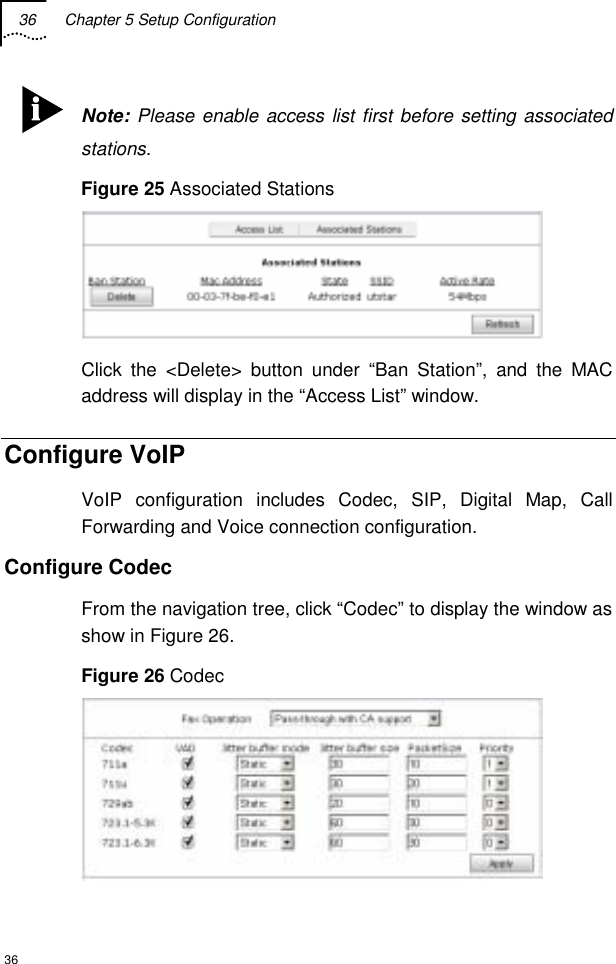
![2 About This Guide 2 Icon Notice Type Description ESD Information that indicates proper grounding precautions is required before handling a product. Text The following table lists text conventions in this guide. Convention Description Text represented by Courier New Font This typeface represents text that appears on a terminal screen, including, configuration file names (only for system output file names), and command names, for example login. Text represented by bold This typeface represents function names, window tabs, field names, for example, Set the Time field. Text represented as user entry This typeface represents commands entered by the user, for example, cd $HOME. Text represented by “ ” This typeface represents window and dialog box names, directory, file names, process name, and command in text, for example, open the “NE Inventory Management” window. Text represented by [Menu] and [Menu/Sub-menu] This typeface represents menus such as [File], and [File/New] Text represented by <Button> This typeface represents button on screen, function key on the keyboard and icon names for example, click <OK>.](https://usermanual.wiki/UTStarcom-Telecom/1023/User-Guide-506502-Page-14.png)

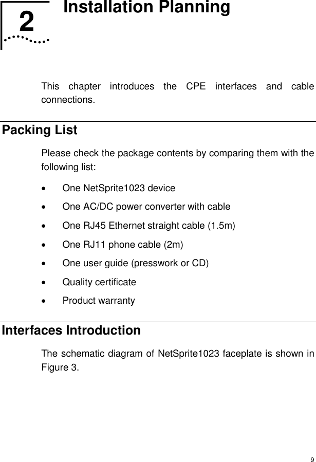
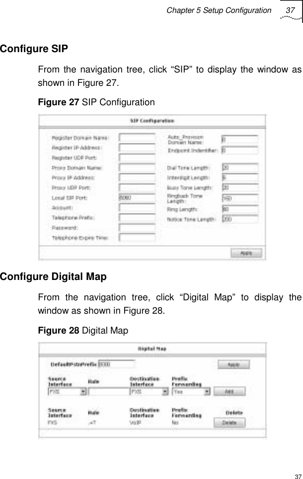
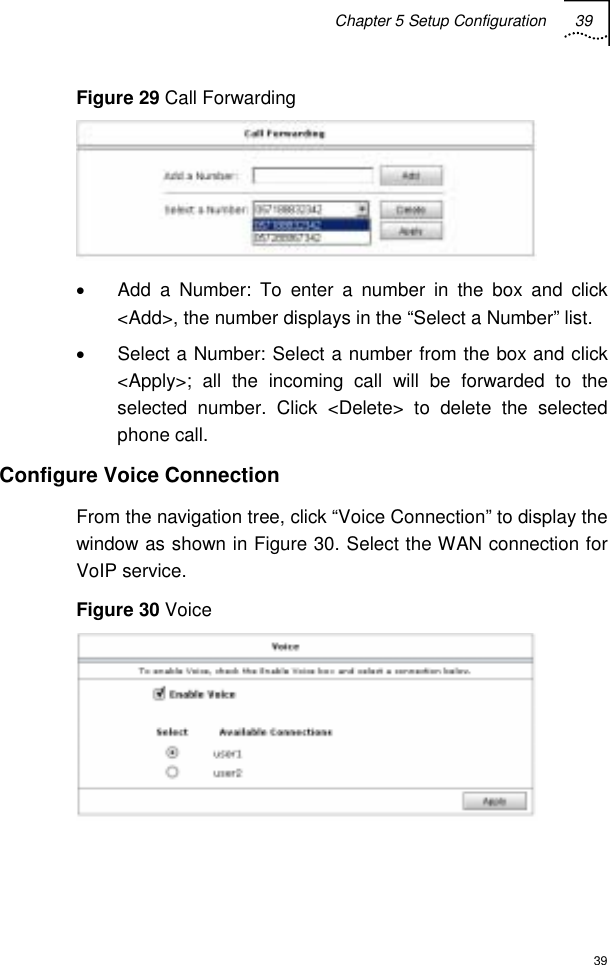
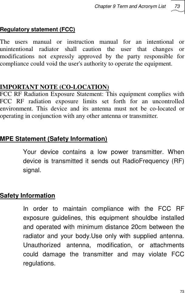
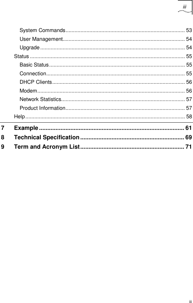
![38 Chapter 5 Setup Configuration 38 Users can set digital rules by the parameters described in Table 6 . Table 6 Digital Map Rule Description Fields Description DefaultPstnPrefix Dial the prefix first and the phone call will be sent to PSTN. The default value is 0000. Users can modify it of up to 5 digits. Source Interface FXS Rule . +T: To represent any number and be sent after interdigit length. . +#: To represent any number and add # before sending the number Users can also set some certain numbers, e.g. (0571) [0-9]{8}: ( ): To enter prefix; [ ]: To enter number range; { }: To enter number digits Destination Interface Possible values: PSTN: To send the call to PSTN VoIP: To send the call to VoIP Prefix Forwarding Choose “Yes” to send the call number with the prefix. Choose “No” to send the number without the prefix. Configure Call Forwarding From the navigation tree, click “Call Forwarding” to display the window as shown in Figure 29](https://usermanual.wiki/UTStarcom-Telecom/1023/User-Guide-506502-Page-50.png)