UTStarcom Telecom 1023 Wireless AP User Manual
UTStarcom Telecom Co., Ltd. Wireless AP Users Manual
Users Manual

NetSprite1023
USER GUIDE
Release: 2.2
Doc. Code: L2 DS02 2202 02 10 00
UTStarcom, Inc.
Copyright © 2004 UTStarcom, Inc. All rights reserved.
No part of this documentation may be reproduced in any form or by any means or
used to make any derivative work (such as translation, transformation, or
adaptation) without prior, express and written permission from UTStarcom, Inc.
UTStarcom, Inc. reserves the right to revise this documentation and to make
changes in content from time to time without obligation on the part of UTStarcom,
Inc. to provide notification of such revision or changes.
UTStarcom, Inc. provides this documentation without warranty of any kind, implied
or expressed, including but not limited to, the implied warranties of merchantability
and fitness for a particular purpose. UTStarcom may make improvements or
changes in the product(s) and/or the program(s) described in this documentation
at any time.
UNITED STATES GOVERNMENT LEGENDS:
If you are a United States government agency, then this documentation and the
software described herein are provided to you subject to the following:
United States Government Legend: All technical data and computer software is
commercial in nature and developed solely at private expense. Software is
delivered as Commercial Computer Software as defined in DFARS 252.227-7014
(June 1995) or as a commercial item as defined in FAR 2.101(a) and as such is
provided with only such rights as are provided in UTStarcom's standard
commercial license for the Software. Technical data is provided with limited rights
only as provided in DFAR 252.227-7015 (Nov 1995) or FAR 52.227-14 (June
1987), whichever is applicable. You agree not to remove or deface any portion of
any legend provided on any licensed program or documentation contained in, or
delivered to you in conjunction with, this User Guide.
UTStarcom, the UTStarcom logo, PAS, mSwitch, Airstar, WACOS, Netman, Total
Control, and CommWorks are registered trademarks of UTStarcom, Inc. and its
subsidiaries. The UTStarcom name, AN-2000, and the CommWorks logo are
trademarks of UTStarcom, Inc. and its subsidiaries.
Other brand and product names may be registered trademarks or trademarks of
their respective holders.
Any rights not expressly granted herein are firmly reserved.

i
Contents
About This Guide................................................................................... 1
Introduction.................................................................................................. 1
Conventions................................................................................................. 1
Notice ...................................................................................................... 1
Text.......................................................................................................... 2
Figures and Screen Captures................................................................... 3
Related Documentation ............................................................................... 3
1 Overview......................................................................................... 5
Device Introduction...................................................................................... 5
Feature List.................................................................................................. 6
Application................................................................................................... 6
2 Installation Planning...................................................................... 9
Packing List ................................................................................................. 9
Interfaces Introduction ................................................................................. 9
Cable Connections..................................................................................... 12
3 Before Configuration................................................................... 15
Login NetSprite1023 .................................................................................. 15
Web Page Introduction .............................................................................. 16
4 Quick Start.................................................................................... 19
5 Setup Configuration .................................................................... 23
Configure WAN.......................................................................................... 23
Configure ADSL Connection .................................................................. 23
Configure ADSL Line Setup ................................................................... 29
Configure WLAN........................................................................................ 29
Configure Basic Setup............................................................................ 29

ii
ii
Configure WLAN Security ...................................................................... 31
Configure Management.......................................................................... 34
Configure VoIP .......................................................................................... 36
Configure Codec.................................................................................... 36
Configure SIP......................................................................................... 37
Configure Digital Map............................................................................. 37
Configure Call Forwarding...................................................................... 38
Configure Voice Connection................................................................... 39
Configure LAN........................................................................................... 40
Configure LAN Group............................................................................. 40
Configure DHCP .................................................................................... 41
Configure IP........................................................................................... 41
Configure LAN Clients............................................................................ 42
Configure Isolation................................................................................. 42
Configure Security ..................................................................................... 43
Configure DMZ....................................................................................... 43
Configure IP Filters ................................................................................ 44
Configure Access Control....................................................................... 46
Configure UpnP ..................................................................................... 46
Configure Port Mapping ......................................................................... 47
Configure Routing...................................................................................... 48
Configure Static Routing ........................................................................ 48
Configure Dynamic Routing.................................................................... 49
Others........................................................................................................ 49
Configure SNTP..................................................................................... 49
Configure Multicast ................................................................................ 50
IP QoS....................................................................................................... 50
6 System Management ................................................................... 53
System ...................................................................................................... 53

iii
iii
System Commands................................................................................ 53
User Management.................................................................................. 54
Upgrade................................................................................................. 54
Status ........................................................................................................ 55
Basic Status........................................................................................... 55
Connection............................................................................................. 55
DHCP Clients......................................................................................... 56
Modem................................................................................................... 56
Network Statistics................................................................................... 57
Product Information................................................................................ 57
Help........................................................................................................... 58
7 Example........................................................................................ 61
8 Technical Specification............................................................... 69
9 Term and Acronym List............................................................... 71

iv
iv
List of Figures
Figure 1 Appearance ........................................................................................... 5
Figure 2 Application............................................................................................. 6
Figure 3 Faceplate............................................................................................. 10
Figure 4 Backplane............................................................................................ 12
Figure 5 Login.................................................................................................... 16
Figure 6 Home Page.......................................................................................... 16
Figure 7 Setup................................................................................................... 17
Figure 8 Quick Start........................................................................................... 19
Figure 9 WAN Configuration .............................................................................. 19
Figure 10 Call Forwarding.................................................................................. 20
Figure 11 WLAN................................................................................................ 21
Figure 12 ADSL Connection .............................................................................. 23
Figure 13 PPPoA............................................................................................... 25
Figure 14 Static ................................................................................................. 26
Figure 15 DHCP ................................................................................................ 27
Figure 16 Bridge................................................................................................ 28
Figure 17 CLIP .................................................................................................. 28
Figure 18 ADSL line setup................................................................................. 29
Figure 19 Basic Setup........................................................................................ 30
Figure 20 WLAN Security .................................................................................. 31
Figure 21 WEP .................................................................................................. 32
Figure 22 802.1x................................................................................................ 33
Figure 23 WPA .................................................................................................. 34
Figure 24 WLAN Management........................................................................... 35
Figure 25 Associated Stations ........................................................................... 36
Figure 26 Codec................................................................................................ 36

v
v
Figure 27 SIP Configuration............................................................................... 37
Figure 28 Digital Map......................................................................................... 37
Figure 29 Call Forwarding.................................................................................. 39
Figure 30 Voice ................................................................................................. 39
Figure 31 LAN Group......................................................................................... 40
Figure 32 DHCP ................................................................................................ 41
Figure 33 IP....................................................................................................... 41
Figure 34 LAN Clients........................................................................................ 42
Figure 35 LAN Isolation ..................................................................................... 43
Figure 36 DMZ................................................................................................... 43
Figure 37 IP Filters ............................................................................................ 44
Figure 38 View................................................................................................... 45
Figure 39 Custom IP Filters ............................................................................... 45
Figure 40 Access Control................................................................................... 46
Figure 41 UPnP................................................................................................. 47
Figure 42 Port Mapping ..................................................................................... 47
Figure 43 Custom Port Mapping ........................................................................ 48
Figure 44 Static Routing .................................................................................... 48
Figure 45 Dynamic Routing................................................................................ 49
Figure 46 SNTP................................................................................................. 49
Figure 47 Multicast ............................................................................................ 50
Figure 48 IP QoS............................................................................................... 50
Figure 49 IP QoS Traffic Rule............................................................................ 51
Figure 50 System Commands............................................................................ 53
Figure 51 User Management ............................................................................. 54
Figure 52 Updating System Online (FTP) .......................................................... 55
Figure 53 Status Information.............................................................................. 55
Figure 54 Connection Status.............................................................................. 56
Figure 55 DHCP Clients..................................................................................... 56
Figure 56 Modem Status.................................................................................... 57

vi
vi
Figure 57 Network Statistics-Wireless................................................................ 57
Figure 58 Product Information............................................................................ 58
Figure 59 Help................................................................................................... 59
Figure 60 Firewall .............................................................................................. 60
Figure 61 Example............................................................................................. 61
Figure 62 Connction1......................................................................................... 63
Figure 63 Connection2....................................................................................... 63
Figure 64 LAN Configuration.............................................................................. 64
Figure 65 DHCP Configuration .......................................................................... 64
Figure 66 SIP..................................................................................................... 65
Figure 67 Voice ................................................................................................. 65
Figure 68 SSID.................................................................................................. 66
Figure 69 Save and Restart AP ......................................................................... 67

vii
vii
List of Tables
Table 1 Faceplate Definition............................................................................... 10
Table 2 Backplane Definition.............................................................................. 12
Table 3 WLAN Settings Description ................................................................... 21
Table 4 PPPoE Description................................................................................ 24
Table 5 Basic Setup Description......................................................................... 30
Table 6 Digital Map Rule Description.................................................................. 38
Table 7 IP Filters Description ............................................................................. 44
1
About This Guide
Introduction
This user guide shows you how to connect the device and
configure it through Web interface.
Conventions
This guide may contain notices, figures, screen captures, and
certain text conventions.
Notice
The following table lists notices icons used in this guide.
Icon Notice Type Description
Note Information that contains important
features or instructions but is not
hazard-related.
Caution
Information to alert of potential
damage to a program, data, system, or
device. If not avoided, may result in
minor or moderate injury. It may also
alert against unsafe practices and
potential program, data, system,
device damage.
Warning
Information to alert of operations that
may cause potential accident,
casualty, personal injury, fatality or
potential electrical hazard. If not
avoided, could result in death or
serious injury.

2 About This Guide
2
Icon Notice Type Description
ESD Information that indicates proper
grounding precautions is required
before handling a product.
Text
The following table lists text conventions in this guide.
Convention Description
Text represented
by Courier New
Font
This typeface represents text that
appears on a terminal screen, including,
configuration file names (only for system
output file names), and command names,
for example login.
Text represented
by bold
This typeface represents function names,
window tabs, field names, for example, Set
the Time field.
Text represented
as user entry
This typeface represents commands
entered by the user, for example, cd
$HOME.
Text represented
by “ ”
This typeface represents window and dialog
box names, directory, file names, process
name, and command in text, for example,
open the “NE Inventory Management”
window.
Text represented
by [Menu] and
[Menu/Sub-menu]
This typeface represents menus such as
[File], and [File/New]
Text represented
by <Button>
This typeface represents button on screen,
function key on the keyboard and icon
names for example, click <OK>.

About This Guide 3
3
Convention Description
Text represented
by Document
Name
This typeface represents documents for
reference, for example, Netman 2020-
based AN2000B-900 Installation Guide
Text represented
by
# File format:
This typeface represents files in Unix/Linux
system flies.
Figures and Screen Captures
This guide provides figures and screen captures as example.
These examples contain sample data. This data may vary from
the actual data on an installed system.
Related Documentation
The following document contains further information about
installation of NetSprite1023:
• NetSprite1023 Quick Start Guide
5
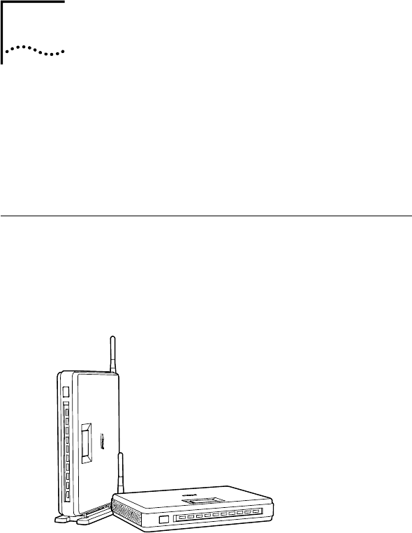
1 Overview
NetSprite1023 is a multifunctional network terminal of CPE
(Customer Premises Equipment) family. The device provides
integrated voice and data services over ADSL (Asymmetrical
Digital Subscriber Loop ) WAN (Wide Area Network)
connection.
Device Introduction
Figure 1 pictures the NetSprite1023 device. The CPE can be
easily placed indoors, lying, stand-up or hanging with the
advantage of its small footprint.
Figure 1 Appearance
1
6 Chapter 1 Overview
6
Feature List
• Provides ADSL uplink connecting to WAN
• Provides POTS(Plain Old Telephone Service)interface
to implement plain telephone service or VoIP (Voice over
Internet Protocol)
• Provides 4 Ethernet interfaces to implement high-speed
data services
• Built-in AP, supports 802.11b/g for wireless LAN
application
• DHCP (Dynamic Host Configuration Protocol)
Server/Client
• Provides web-based management
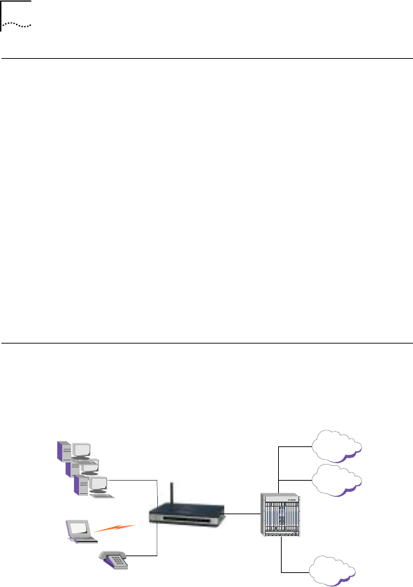
Application
The application of NetSprite1023 is shown in Figure 2.
Figure 2 Application
4×
Ethernet
RJ11
RJ11
PSTN
802.11b/g
WLAN
Phone
DSLAN
Internet
SoftSwitch
NetSprite1023
LAN

Chapter 1 Overview 7
7
The CPE provides an ADSL uplink port connecting to WAN. For
data services, subscribers can access Internet via WLAN or
Ethernet interface. For voice services, the device supports both
VoIP and PSTN calls. These two services will finally go to
softswitch network and Internet separately. VoIP is the
preferred telephony service for users as it offers a lower call
charge than PSTN. However, PSTN service is supported for
complement of VoIP service when PSTN is the designated call
path, VoIP service is not available, or during a power outage of
the device.

9
2 Installation Planning
This chapter introduces the CPE interfaces and cable
connections.
Packing List
Please check the package contents by comparing them with the
following list:
• One NetSprite1023 device
• One AC/DC power converter with cable
• One RJ45 Ethernet straight cable (1.5m)
• One RJ11 phone cable (2m)
• One user guide (presswork or CD)
• Quality certificate
• Product warranty
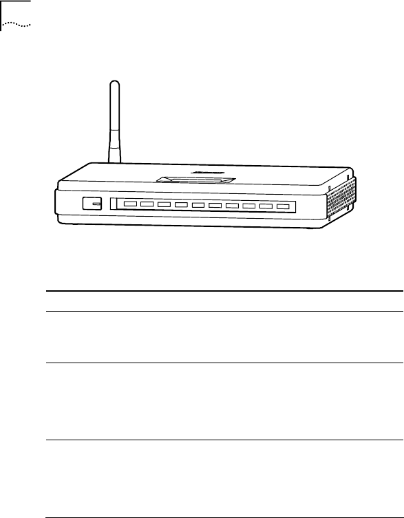
Interfaces Introduction
The schematic diagram of NetSprite1023 faceplate is shown in
Figure 3.
2
10 Chapter 2 Installation Planning
10
Figure 3 Faceplate
CALL FW PWRAL ARM WLAN VOIP LI NKDATA LAN1LAN2LAN3 LAN4
Table 1 describes LEDs and one button in the faceplate.
Table 1 Faceplate Definition
LED Name Color Definition
PWR
(Power) Green
This LED indicates power status:
On: when power is applied to the device
Off: when power is off
ALARM Red
This LED indicates operational status:
On: when the hardware/software
malfunction is detected and not able to
continue normal operation
Off: when device operation is normal
WLAN Green
This LED indicates WLAN status:
Flash: when there’re wireless stations
accessed to the device
Off: when there’re no wireless stations
accessed to the device

Chapter 2 Installation Planning 11
11
LED Name Color Definition
VOIP Green
This LED indicates BB Phone VoIP status:
On: when device successfully registered
with call agent
Off: when device failed to register with call
agent
Flash: when VoIP call is in progress or
device is upgrading
LINK Green
This LED indicates ADSL link status:
On: when ADSL link is up
Off: when ADSL link is down
Flash: when ADSL link is training
DATA Green
This LED indicates ADSL activity:
Flash: when transmitting or receiving
packets on ADSL port
Off: When there is no ADSL connection,
ADSL link is down, or ADSL link is in
training state
LAN1-
LAN4 Green
Each LED indicates one Ethernet LAN link
status:
On: when the Ethernet link is up and
connected
Off: when there is no connection, or the
Ethernet link is down
CALLFW Green
This LED indicates the status of call
forwarding switch:
On: when call forwarding is enabled
Off: when Call forwarding is disabled
Local Call
Forwarding
Button Push the button to enable/disable local
call forwarding function
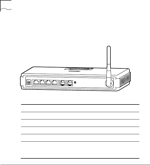
12 Chapter 2 Installation Planning
12
Figure 4 shows a schematic diagram of the backplane. Table 2
describes the interfaces and one button in the backplane.
Figure 4 Backplane
LAN1 LAN2 LAN3 LAN4
POWER LINE PHONE
RESET
Table 2 Backplane Definition
Interfaces Type Description
POWER Barrel To connect to DC power
LAN1-LAN4 RJ45 To connect to PC
LINE RJ11 To connect to ADSL line
PHONE RJ11 To connect to phone
Reset Button Recessed
pinhole Hold down for 5 seconds, the
device will reboot and reset
to factory defaults
Cable Connections
After verifying proper environmental conditions such as
temperature, humidity and power supply, users may start the
cable connections as following:
1 Connect the PSTN line to the port marked “LINE” using a
RJ11 phone cable.

Chapter 2 Installation Planning 13
13
2 Connect a regular telephone instrument to the port marked
“Phone” using a RJ11 phone cable.
3 Connect computers using RJ45 cables. Plug one end of
the RJ45 cable to the Ethernet port of PC/Lap Top and the
other end to any one of the CPE RJ45 ports marked from
“LAN1” to “LAN4”.
4 If users have subscribed to VoIP service, the green VoIP
Ready LED should light after power on. This indicates that
VoIP service is available and ready for use. Users may
have to wait for several minutes.
5 NetSprite1023 has a built-in WLAN card. Users may install
a wireless card for each PC and set up wireless LAN
(WLAN).
6 Power connection: Plug the AC/DC power converter to an
AC wall socket and the other end of the cable to the device
socket marked “POWER”.

15
3 Before Configuration
NetSprite1023 provides Web-based management of the device.
To access the CPE, users can connect a PC to any one of the
Ethernet ports. The Ethernet and WLAN interfaces use the
same IP address (192.168.1.1/255.255.255.0) by default.
Login NetSprite1023
Users can access the CPE as following:
1 Set the IP address on the PC connecting to the CPE. The
IP address must be in the same subnet as the LAN
interface, for example, 192.168.1.10/255.255.255.0.
2 Open the Internet Explorer (IE) on the PC and enter:
http://192.168.1.1.
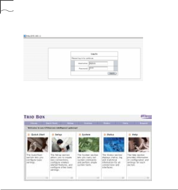
3 The login window will appear as shown in Figure 5. Enter
the user name and password. The default user name and
password for administrator are both “Admin”.
NetSprite1023 also provides username of “user” and
password of “user123” for end-users.
3
16 Chapter 3 Before Configuration
16
Figure 5 Login
4 Click <Log in> to enter the NetSprite1023 home page as
shown in Figure 6.
Figure 6 Home Page
Web Page Introduction
As shown from the menu bar in home page, NetSprite1023
provides some configuration and management options. The
field below the menu bar is 5 links with detailed information.
Select “Setup” from the menu bar, for example, to display the
window as shown in Figure 7. The left navigation tree lays out
all the configurations of “setup” configuration. Click any one
from the tree to enter the corresponding window.
Chapter 3 Before Configuration 17
17
Figure 7 Setup
Following introduces those options in the menu bar:
• Home: Provides links to “Quick Start”, “Setup”, “System”,
“Status” and “Help”
• Quick Start: A guide for users to complete basic
configurations step by step
• Setup: Provides WAN, LAN, VoIP, WLAN, security, Route
and IP QoS configurations.
• System: Provides system commands including save,
reboot and reset to defaults. It also provides user
management and upgrading.
• Status: Indicates interfaces and connection status and
statistics
• Help: Provides details of CPE functions
• Logout: To logout Web and return to the “Login” window
19
4 Quick Start
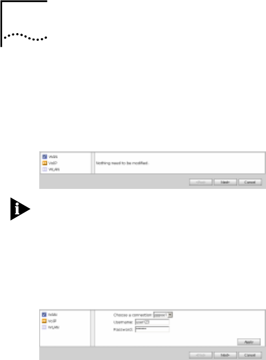
From the menu bar, select the “Quick Start” to display the
window as shown in Figure 8. “Quick Start” provides WAN,
VoIP and WLAN configurations. WAN configuration is needed
only when WAN connection type is PPPoE or PPPoA.
Figure 8 Quick Start
Note: For details of WAN connection, please refer to the
section “Configure ADSL Connection” in chapter 5.
• WAN configuration
Users can modify the username and password of selected WAN
connection. Click <Apply> to initiate the configuration.
Figure 9 WAN Configuration
• VoIP configuration
Click <next> to display the window as shown in Figure 10.
4
20 Chapter 4 Quick Start
20
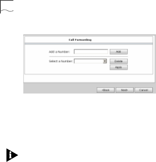
Figure 10 Call Forwarding
Users can add several telephone numbers in the “Add a
Number” box and click <Add>, the numbers are listed in the
“Select a Number” drop-down list box. Select one number from
the list and click <Apply>, all the incoming calls are forwarded to
the designated number. Click <Delete> to delete the selected
number.
Note: Please push the CALLFW button in the CPE faceplate to
enable the function.
• WLAN
Click <Next> to display the window as shown in Figure 11.
Table 3 describes those wireless parameters.
Chapter 4 Quick Start 21
21
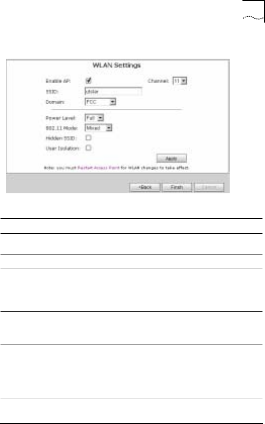
Figure 11 WLAN
Table 3 WLAN Settings Description
Fields Description Default
Enable AP Enabled
Channel 1-14 11
SSID
The SSID is for subscribers
grouping. Only the wireless stations
that have the same SSID as the CPE
can access the device.
utstar
Domain Possible values: FCC, IC, ETSI,
SPAIN, FRANCE, MKK, MKK1, US,
WORLD FCC
Power Level
The transmitting power level of the
CPE wireless interface, i.e. the
percentage of maximum transmitting
power. Possible values: Full,50
%,25 %,12 %,6 %
Full
802.11 Mode CPE wireless work mode. Possible
values: Mixed, 11b only, 11g only Mixed

22 Chapter 4 Quick Start
22
Fields Description Default
Hidden SSID
Enable “Hidden SSID” and the CPE
SSID is invisible when indicating the
available network in the user’s
wireless network card.
Disabled
User Isolation Enable “User Isolation” and wireless
stations will separate from each
other. Disabled
Click <Apply> to initiate the configuration. It will take effect after
rebooting the AP.

23
5 Setup Configuration
The “Setup” includes WAN, WLAN, VoIP, LAN, Security, Route,
IP QoS and other configurations.
Configure WAN
WAN configuration includes “ADSL Connection” and “ADSL
Line Setup”configuration.
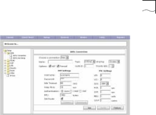
Configure ADSL Connection
From the navigation tree, click “ADSL Connection” to display
the window as shown in Figure 12. The window is of PPPoE
type by default.
Figure 12 ADSL Connection
5

24 Chapter 5 Setup Configuration
24
• PPPoE
Table 4 PPPoE Description
Fields Description Default
Choose a
connection
Select “New” to set up a new
connection. All the connections are
listed in the box.
Type Possible values: PPPoE, PPPoA,
Static, DHCP, Bridge, CLIP
Sharing
Possible values: Disable, Enable, LAN.
Disable: Each PVC of the connection
should be different.
Enable: Multiple connections share the
same PVC.
VLAN: VLAN tag is attached to the
connection.
Disable
QoS
Possible values:
UBR: Unspecified Bit Rate
CBR: Constant Bit Rate
VBR: Variable Bit Rate
UBR
Priority Bits Possible values: 1-7 1
Username/
Password The service provider offers them for
PPPoE connection.
Keep Alive The maximum period that the CPE
initiates connection request 10 min
Set Route Enable “Set Route” and the gateway IP
address the CPE obtained is taken as
the CPE default gateway.
VPI/VCI VPI/VCI is needed for each
connection. The value is compliance
with the setting of DSLAM

Chapter 5 Setup Configuration 25
25
Fields Description Default
PCR, SCR,
MBS, VDVT
PCR and CDVT can be changed in
CBR type; all the parameters can be
changed in VBR type
Note: Users can set different QoS to mark different traffic when
multiple connections share the same PVC.
Click <Add> to add the connection. The CPE will connect
automatically after powered on. The <Connect> button is used
for manually initiate a connection and <Disconnect> to manually
disconnect current connection
• PPPoA
Select “PPPoA” from the “Type” box to display the window as
shown in Figure 13. Please refer to Table 4 for details.
Figure 13 PPPoA
• Static
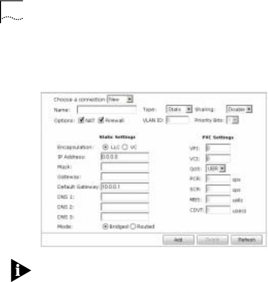
26 Chapter 5 Setup Configuration
26
Select “Static” from the “Type” box to display the window as
shown in Figure 14.
Figure 14 Static
Note: When two connections are used for voice and data, enter
the voice network gateway IP address in the “Gateway” text box
and the data network gateway IP address in the “Default
Gateway” box.
When voice and date services share the same connection,
enter the gateway IP address in the “Default Gateway” box only.
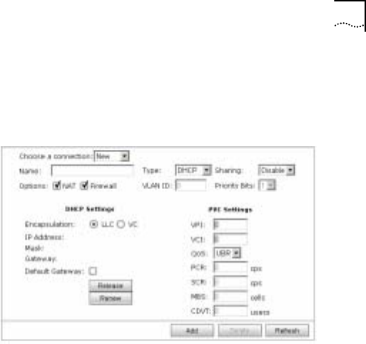
• DHCP
Click “DHCP” in the “Type” box to display the window as shown
in Figure 15. The CPE obtains WAN interface IP address from
the WAN side DHCP server.
Chapter 5 Setup Configuration 27
27
- Default Gateway: Select the box and the CPE will
take the gateway obtained as the CPE default
gateway
Figure 15 DHCP
Click <renew> to get WAN IP address again and <Release> to
release obtained IP address.
• Bridge
Select “Bridge” from the “Type” box to display the window as
shown in Figure 16.
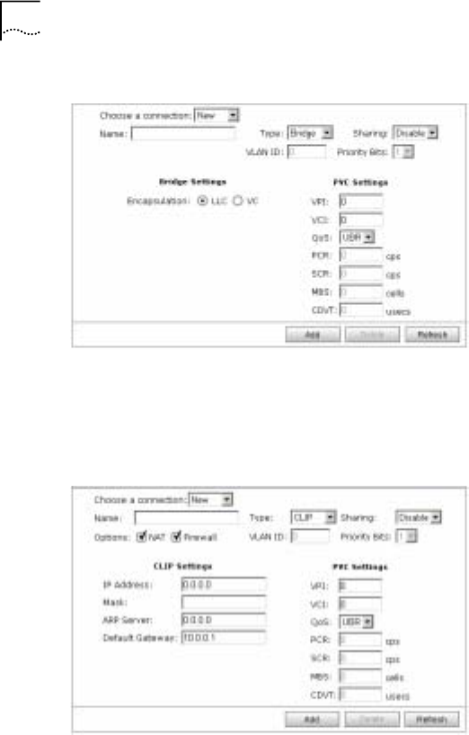
28 Chapter 5 Setup Configuration
28
Figure 16 Bridge
• CLIP (Classical IP over ATM)
Click “CLIP” from the “Type” box to display the window as
shown in Figure 17.
Figure 17 CLIP
Chapter 5 Setup Configuration 29
29
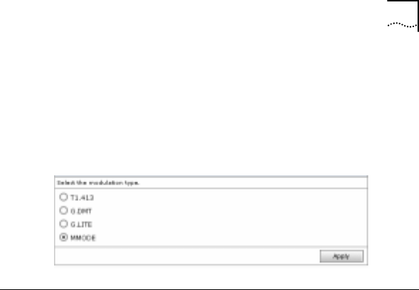
Configure ADSL Line Setup
From the navigation tree, click “ADSL Line Setup” to display the
window as shown in Figure 18. the default modulation type is
“MMODE”(multi-mode).
Figure 18 ADSL line setup
Configure WLAN
WLAN configuration includes “Basic Setup”, “Security” and
“management” configuration.
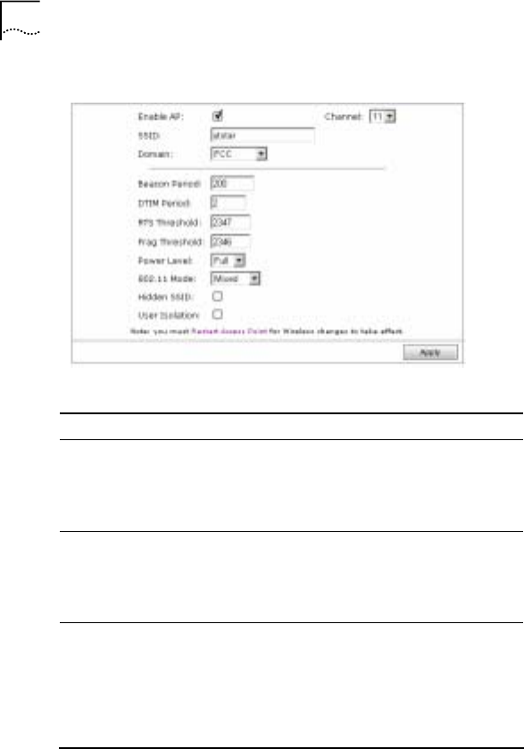
Configure Basic Setup
From the navigation tree, click “Basic Setup” to display the
window as shown in Figure 19.
Table 5 describes the parameters in the window. Please refer to
“WLAN Settings” in chapter 4 for more information of WLAN
configuration.
30 Chapter 5 Setup Configuration
30
Figure 19 Basic Setup
Table 5 Basic Setup Description
Fields Description Default
Beacon Period Interval between Beacon
packets, the Beacon frame
contains network card
information, period of broadcast
to the wireless network.
200(ms)
DTIM Period Interval between Delivery Traffic
Indication Messages. 2, the exact
value is 2
times of
beacon
period
RTS
Threshold WLAN is using the mechanism of
Request To Send/Clear To Send.
RTS/CTS threshold can be set,
RTS/CTS is used when the data
packet size exceeds the
threshold. Choose a setting
within a range of 0 – 2347.
2347
Chapter 5 Setup Configuration 31
31
Fields Description Default
Frag
Threshold Fragment threshold is used to
improve the efficiency in a high
volume wireless network. Any
packet greater than this value
will be fragmented. Choose a
setting within a range of 256 –
2346 bytes.
2346
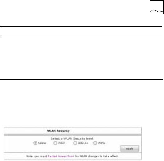
Configure WLAN Security
From the navigation tree, click “Security” to display the window
as shown in Figure 20.
Figure 20 WLAN Security
• None: No security settings
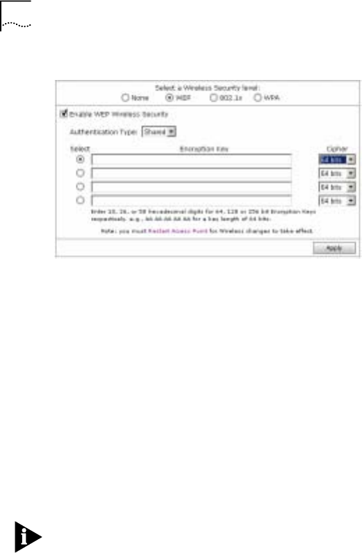
• WEP
Select the “WEP” to display the window as shown in Figure 21.
WEP encryption uses a static secret key. Each wireless station
uses the same key to access the wireless network.
NetSprite1023 supports 64-bit or 128-bit static WEP encryption
to prevent illegal access.
32 Chapter 5 Setup Configuration
32
Figure 21 WEP
Authentication Type:
- Open: To encrypt data frames
- Shared: To encrypt authentication frames during
802.11-authentication process and data frames
- Both: To negotiate “Open” or “Shared” automatically
Encryption Key:
- The password for 64-bit WEP is 10 hexadecimal
digits (0-9, A-F). For example: 11AA22BB33.
- The password for 128-bit WEP is 26 hexadecimal
digits (0-9, A-F).
For example: 00112233445566778899AABBCC.
Note: When WEP encryption is enabled, users can select one
of the keys as the encryption key and set the same in wireless
network card.
Chapter 5 Setup Configuration 33
33
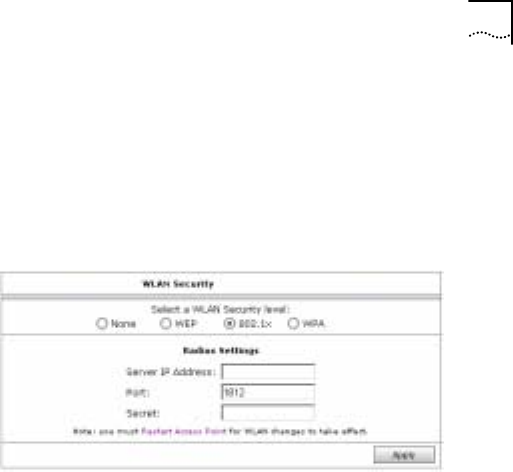
• 802.1x
Select “802.1x” to display the window as shown in Figure 22.
The CPE can implement 802.1x authentication. Users need
802.1x authentication supplicants to initiate 802.1x
authentication request.
Figure 22 802.1x
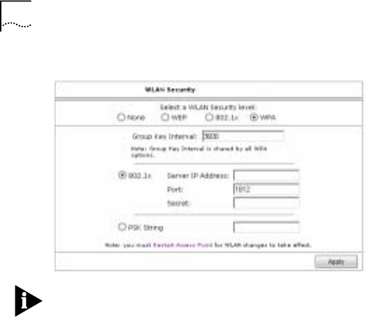
• WPA
Select “WPA” to display the window as shown in Figure 23.
- Group Key Interval: The interval after which the
Radius server will re-negotiate broadcast and
multicast encryption key
- 802.1x: To enter server IP address, Port and Secret.
Data traffic will be encrypted between Radius server
and wireless station.
- PSK String: When PSK string is enabled, users set
the same in wireless cards. Data traffic will be
encrypted between CPE and wireless stations.
34 Chapter 5 Setup Configuration
34
Figure 23 WPA
Note: The security settings will take effect after rebooting the
WLAN module.
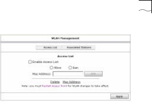
Configure Management
From the navigation tree, click “Management” to display the
window as shown in Figure 24. The default web page is of
“Access List”.
Chapter 5 Setup Configuration 35
35
Figure 24 WLAN Management
• Access List
- Select “Allow” and enter MAC address in the “Mac
Address” box, thus only the wireless station of the
MAC address can access the CPE.
- Select “BAN” and enter MAC address in the “Mac
Address” box, thus the wireless station of the MAC
address can’t access the CPE.
- MAC Address: Enter a MAC address in the box and
click <Add>, the MAC address will list below. Click
<Delete> to cancel the access list settings.
Click <Apply> to initiate the configuration and it will take effect
after rebooting.
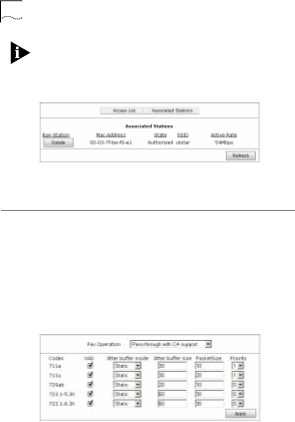
• Associated Stations
Click “Associated Stations” to display the window as shown in
Figure 25. All the wireless stations connected to the CPE are
listed on the window.
36 Chapter 5 Setup Configuration
36
Note: Please enable access list first before setting associated
stations.
Figure 25 Associated Stations
Click the <Delete> button under “Ban Station”, and the MAC
address will display in the “Access List” window.
Configure VoIP
VoIP configuration includes Codec, SIP, Digital Map, Call
Forwarding and Voice connection configuration.
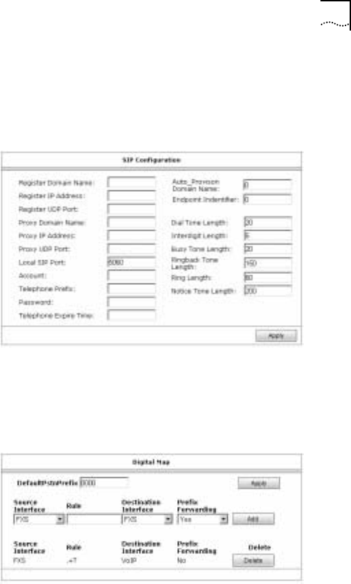
Configure Codec
From the navigation tree, click “Codec” to display the window as
show in Figure 26.
Figure 26 Codec
Chapter 5 Setup Configuration 37
37
Configure SIP
From the navigation tree, click “SIP” to display the window as
shown in Figure 27.
Figure 27 SIP Configuration
Configure Digital Map
From the navigation tree, click “Digital Map” to display the
window as shown in Figure 28.
Figure 28 Digital Map

38 Chapter 5 Setup Configuration
38
Users can set digital rules by the parameters described in Table
6 .
Table 6 Digital Map Rule Description
Fields Description
DefaultPstn
Prefix
Dial the prefix first and the phone call will be sent
to PSTN. The default value is 0000. Users can
modify it of up to 5 digits.
Source
Interface FXS
Rule
. +T: To represent any number and be sent after
interdigit length.
. +#: To represent any number and add # before
sending the number
Users can also set some certain numbers, e.g.
(0571) [0-9]{8}:
( ): To enter prefix;
[ ]: To enter number range;
{ }: To enter number digits
Destination
Interface
Possible values:
PSTN: To send the call to PSTN
VoIP: To send the call to VoIP
Prefix
Forwarding
Choose “Yes” to send the call number with the
prefix. Choose “No” to send the number without the
prefix.
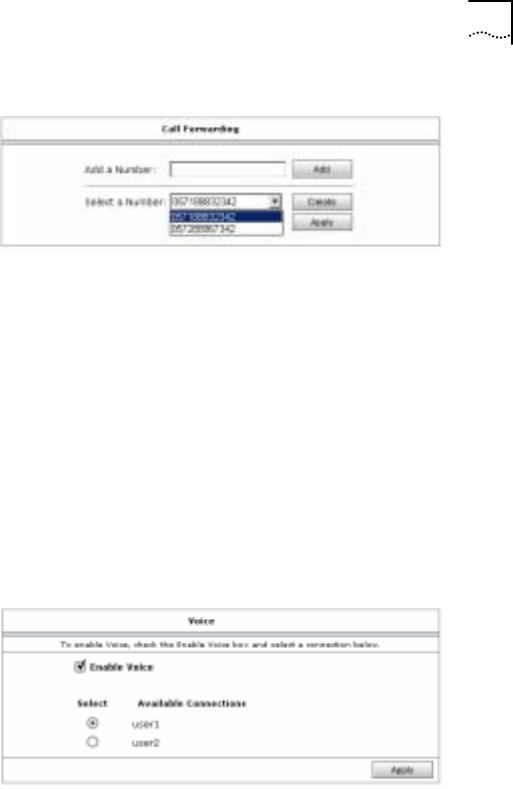
Configure Call Forwarding
From the navigation tree, click “Call Forwarding” to display the
window as shown in Figure 29
Chapter 5 Setup Configuration 39
39
Figure 29 Call Forwarding
• Add a Number: To enter a number in the box and click
<Add>, the number displays in the “Select a Number” list.
• Select a Number: Select a number from the box and click
<Apply>; all the incoming call will be forwarded to the
selected number. Click <Delete> to delete the selected
phone call.
Configure Voice Connection
From the navigation tree, click “Voice Connection” to display the
window as shown in Figure 30. Select the WAN connection for
VoIP service.
Figure 30 Voice
40 Chapter 5 Setup Configuration
40
Configure LAN
LAN configuration includes LAN Group, DHCP, IP, Client and
Isolation configuration.
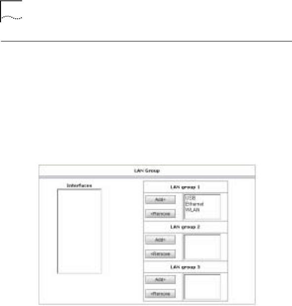
Configure LAN Group
From the navigation tree, click “LAN Group” to display the
window as shown in Figure 31.
Figure 31 LAN Group
NetSprite1023 provides LAN groups. Users can set different IP
addresses to each group. The Ethernet and WLAN interfaces
are of the same IP address by default (192.168.1.1) in LAN
group 1. USB is unavailable.
Select one interface and click <Remove>, it will be removed to
the “Interface” box. The <Add> button is to remove the interface
from the “Interface” box to the designated LAN group.
Chapter 5 Setup Configuration 41
41
Note: The Ethernet can’t be moved from LAN Group 1.
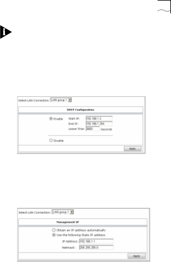
Configure DHCP
From the navigation tree, click “DHCP” to display the window as
shown in Figure 32.
Figure 32 DHCP
Configure IP
From the navigation tree, click “IP” to display the window as
shown in Figure 33. Users can set IP address for selected LAN
group.
Figure 33 IP
42 Chapter 5 Setup Configuration
42
• Obtain an IP address automatically: To obtain WAN
interface IP address from DHCP server of LAN side
• Use the following static address: To manually set WAN
interface IP address
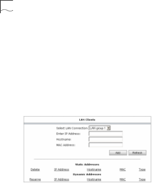
Configure LAN Clients
From the navigation tree, click “Clients” to display the window
as shown in Figure 34. Users can set IP address to the
designated MAC address. The IP address is in the selected
LAN group subnet.
Figure 34 LAN Clients
The “Static Address” area displays all the LAN clients set by the
“LAN Clients” configuration and the “Dynamic Address” area
displays all the clients set by DHCP.
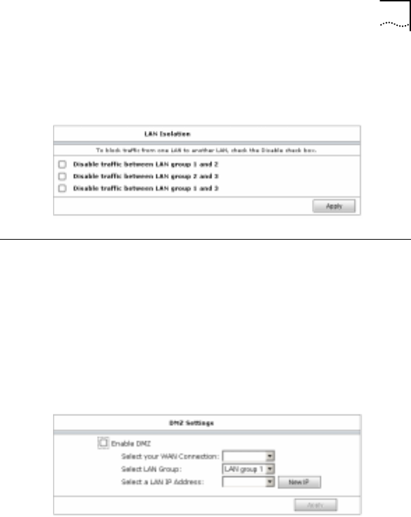
Configure Isolation
From the navigation tree, click “Isolation” to display the window
as shown in Figure 35.
Chapter 5 Setup Configuration 43
43
Select one option and the LAN users of one LAN group can’t
access the others.
Figure 35 LAN Isolation
Configure Security
The security configuration includes DMZ, IP Filters, Access
Control, UpnP and Port Mapping configuration.
Configure DMZ
From the navigation tree, click “DMZ” to display the window as
shown in Figure 36.
Figure 36 DMZ
Enable DMZ and all the service will be forwarded from the
selected WAN interface to the LAN client. Click <New IP> to
configure LAN clients.
44 Chapter 5 Setup Configuration
44
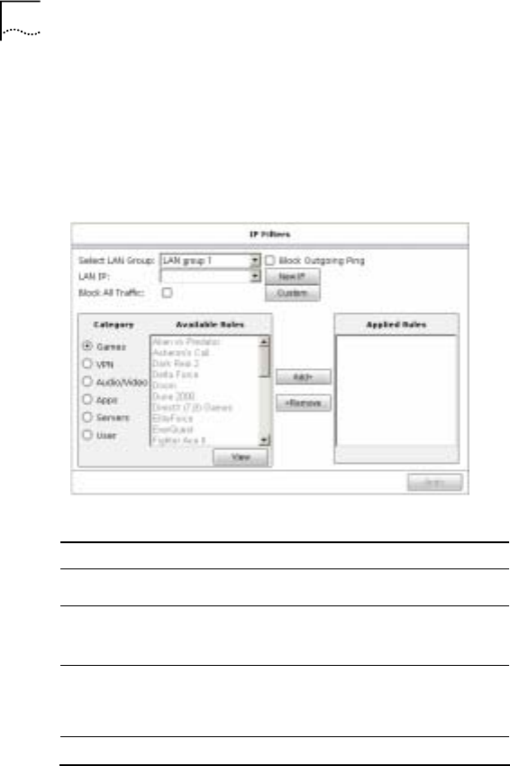
Configure IP Filters
From the navigation tree, click “IP Filters” to display the window
as shown in Figure 37. It provides to block user’s LAN PC from
accessing some Internet services.
Figure 37 IP Filters
Table 7 IP Filters Description
Fields Description
Select LAN Group To select the LAN group from the list
LAN IP To select one LAN IP. The list box
displays all the LAN IP set by “LAN
Clients”.
New IP To add a new LAN IP. Click “New IP”
to display the window of “LAN Clients”.
Block Outgoing Ping To forbid the ping test to WAN side
Chapter 5 Setup Configuration 45
45
Fields Description
Block All Traffic To block all the LAN IP to access WAN
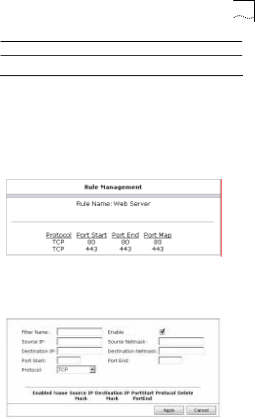
From the window, users can select certain service to apply IP
filter. Select category in the “Category” area and select one rule
in the “Available Rules” area. Click the <Add> button and the
selected service is moved to “Applied Rules”. Users can query
the protocol and port number of the selected service by clicking
the <View> button.
Figure 38 View
• Custom: Users can custom IP filter rules by this link.
Click “Custom” to display the window as shown in Figure 39.
Figure 39 Custom IP Filters
46 Chapter 5 Setup Configuration
46
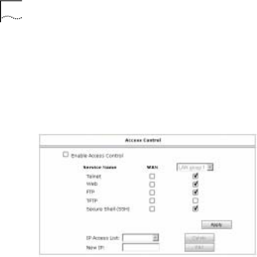
Configure Access Control
From the navigation tree, click “Access Control” to display the
window as shown in Figure 40. Users can select service names
under the “WAN” and “LAN” to implement access control from
WAN or LAN interface.
Figure 40 Access Control
Users can set IP addresses that only these IP addresses can
access the CPE. Enter an IP address in the “New IP” box and
Click <Add>. The IP will appear in the “IP Access List” box.
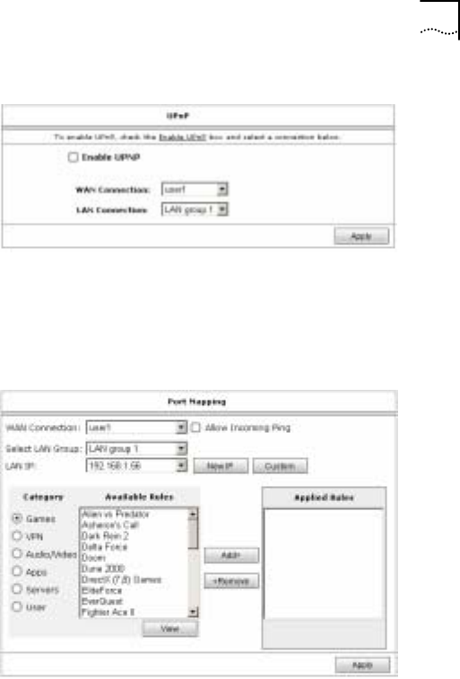
Configure UpnP
From the navigation tree, click “UpnP” to display the window as
shown in Figure 41. Users should enable the function when the
applications need UPnP support such as MSN.
Chapter 5 Setup Configuration 47
47
Figure 41 UPnP
Configure Port Mapping
From the navigation tree, click “Port Mapping” to display the
window as shown in Figure 42.
Figure 42 Port Mapping
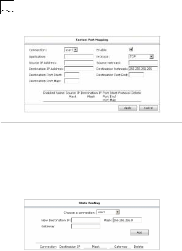
Users can set port forwarding rules in the window or custom
rules by “custom” as shown in Figure 43.
48 Chapter 5 Setup Configuration
48
Figure 43 Custom Port Mapping
Configure Routing
Route configuration includes Static and Dynamic Routing
configuration.
Configure Static Routing
From the navigation tree, click “Static” to display the window as
shown in Figure 44.
Figure 44 Static Routing
Chapter 5 Setup Configuration 49
49
Configure Dynamic Routing
From the navigation tree, click “Dynamic” to display the window
as shown in Figure 45.
Figure 45 Dynamic Routing
Others
NetSprite1023 also provides SNTP and Multicast configuration.
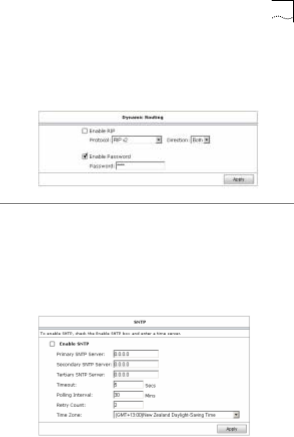
Configure SNTP
From the navigation tree, click “SNTP” to display the window as
shown in Figure 46.
Figure 46 SNTP
50 Chapter 5 Setup Configuration
50
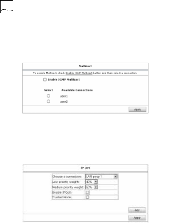
Configure Multicast
From the navigation tree, click “Multicast: to display the window
as shown in Figure 47.
Figure 47 Multicast
IP QoS
From the navigation tree, click “IP QoS” to display the window
as shown in Figure 48.
Figure 48 IP QoS
Select the value in “Low priority weight” and “Medium priority
weight” list. Ensure the sum of these two values is equal to
100%. Select the “Enable IPQoS” box to enable the function.
Chapter 5 Setup Configuration 51
51
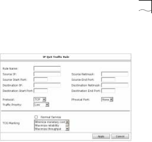
Click <Add> to display the window as show in Figure 49. Users
can set IP QoS rules.
Figure 49 IP QoS Traffic Rule
53
6 System Management
System
The “System” includes Commands, User, and Upgrade.
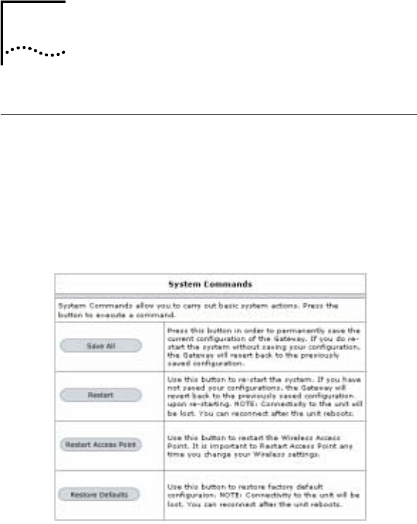
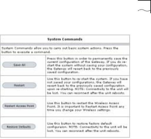
System Commands
From the navigation tree, click “Command” to display the
window as shown in Figure 50.
Figure 50 System Commands
• Save all: Clicks “Save All” and all the configurations will be
saved
6
54 Chapter 6 System Management
54
• Restart: Clicks “Restart” and the CPE will reboot
• Restart Access Point: To restart the WLAN module. It’s
required in wireless configurations.
• Restore Defaults: Clicks “Restore Defaults” and the CPE
will reboot restoring to factory defaults.
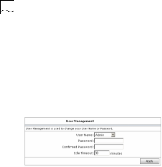
User Management
From the navigation tree, click “User” to display the window as
shown in Figure 51.
Figure 51 User Management
Users can modify password and idle timeout of “Admin” or
“User”.
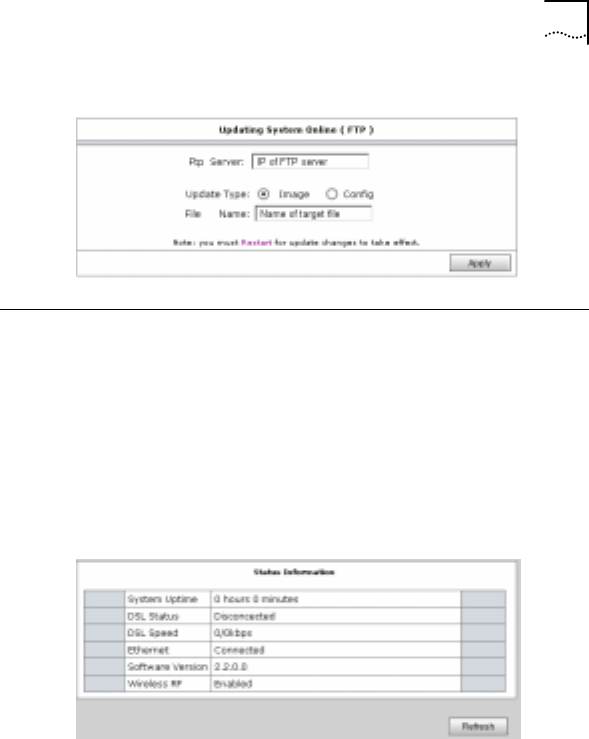
Upgrade
From the navigation tree, click “Upgrade” to display the window
as shown in Figure 52.
Enter the IP address of the FTP server, updating file type and
the file name; users can update the CPE via FTP.
Chapter 6 System Management 55
55
Figure 52 Updating System Online (FTP)
Status
The “Status” includes Basic Status, Connection, DHCP Clients,
Modem, Network Statistics and Production Information.
Basic Status
From the navigation tree, click “Basic Status” to display the
window as show in Figure 53.
Figure 53 Status Information
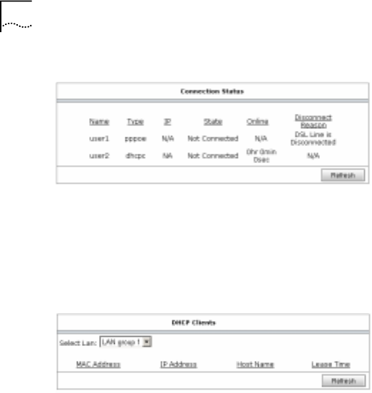
Connection
From the navigation tree, click “Connection” to display the
window as shown in Figure 54. It indicates information of WAN
connections.
56 Chapter 6 System Management
56
Figure 54 Connection Status
DHCP Clients
From the navigation tree, click “DHCP Clients” to display the
window as shown in Figure 55. It indicates all the DHCP clients
connected to the CPE.
Figure 55 DHCP Clients
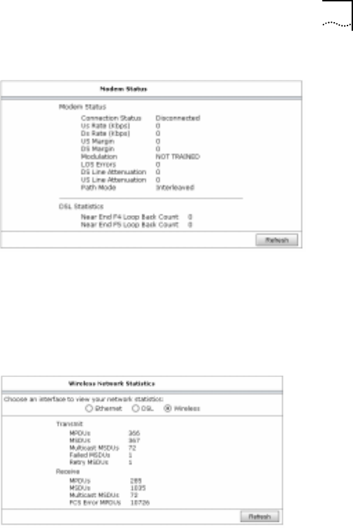
Modem
From the navigation tree, click “Modem” to display the window
as show in Figure 56. It indicates ADSL line information.
Chapter 6 System Management 57
57
Figure 56 Modem Status
Network Statistics
From the navigation tree, click “Network Statistics” to display
the window as shown in Figure 57. Users can select “Ethernet”,
“DSL” or “Wireless” to indicate corresponding network statistics.
Figure 57 Network Statistics-Wireless
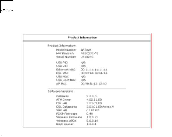
Product Information
From the navigation tree, click “Product Information” to display
the window as shown in Figure 58.
58 Chapter 6 System Management
58
Figure 58 Product Information
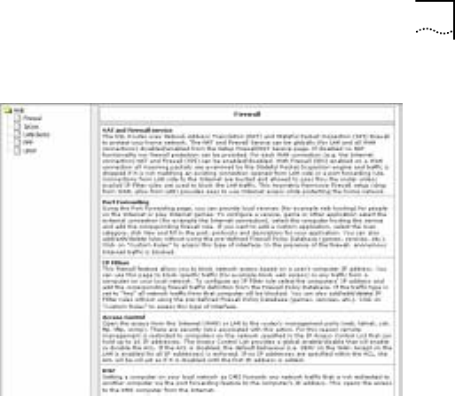
Help
From the menu bar, click “Help” to display the window as shown
in Figure 59. the “Help” gives detailed description involving
Firewall, IP QoS, LAN Clients, PPP and UpnP function.
Chapter 6 System Management 59
59
Figure 59 Help
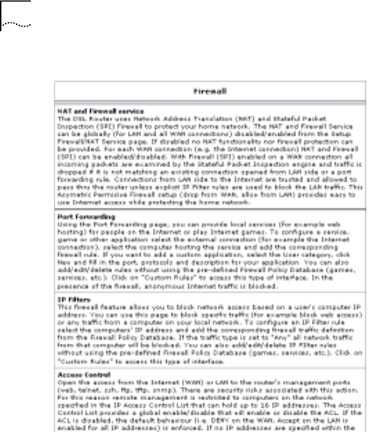
For example, click “Firewall” from the left tree to display the
window as shown in Figure 60. It includes NAT and Firewall,
Port Forwarding, IP Filters, Access Control and so on.
60 Chapter 6 System Management
60
Figure 60 Firewall
61
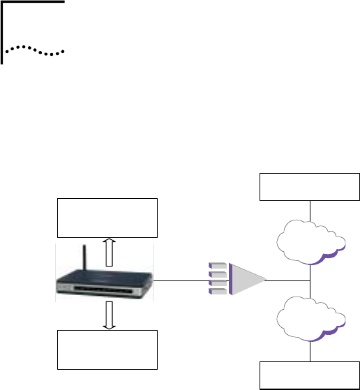
7 Example
This chapter introduces one example and the schematic
diagram is shown in Figure 61.
Figure 61 Example
IP DSLAM
IP:192.168.2.10
GW:192.168.2.1
WAN Connection 2
IP:192.168.3.10
GW:192.168.3.1
RJ11
Voice
Data
WAN Connection 1
Network:192.168.2.0/24
GW:192.168.2.1
Network:192.168.3.0/24
GW:192.168.3.1
NetSprite1023
The CPE basic configuration includes ADSL, LAN, VoIP and
wireless configuration.
• ADSL:
Two WAN connections are used for voice and data services
separately.
- connection1: Used for voice service; type: Static;
VPI/VCI: 0/35
7

62 Chapter 7 Example
62
- connection2: Used for data service; type: Static;
VPI/VCI: 8/35. DNS: 192.168.9.21, 192.168.9.23
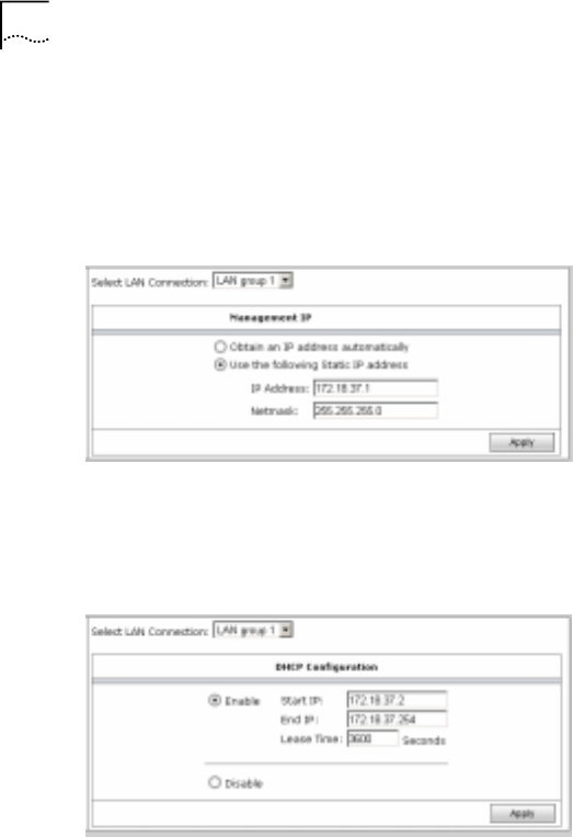
• LAN
- LAN Group1 IP address: 172.18.37.1/255.255.255.0
- Enable DHCP Server
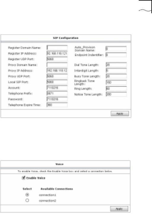
• VoIP
- Configure SIP
- Enable the WAN connection for voice
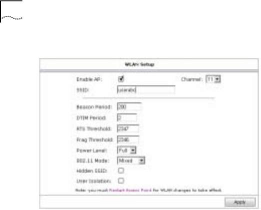
• WLAN
- Set the CPE SSID: userabc
- Set SSID of user’s wireless network card: userabc
Step1: Configure WAN connection of “connectio1”.
Click “Setup/WAN/ADSL Connection” to display the window as
shown in Figure 62.
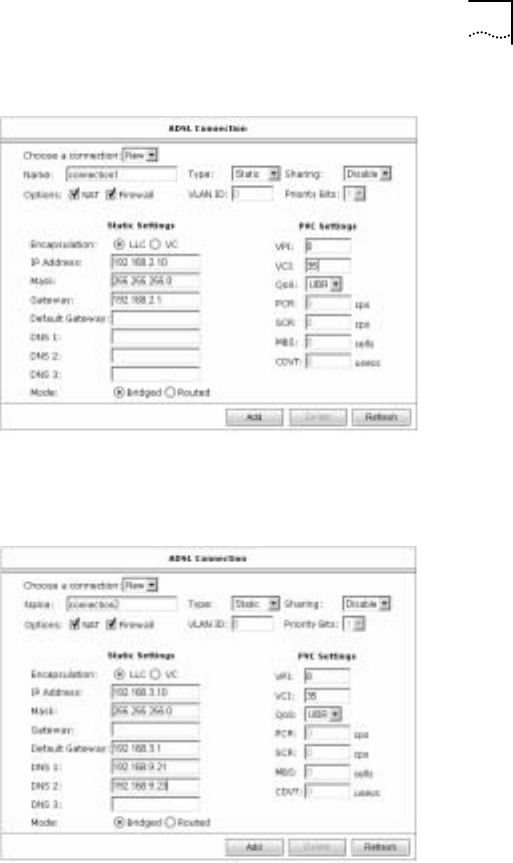
Chapter 7 Example 63
63
Figure 62 Connction1
Step2: Configure WAN connection of “connection2” for data
service.
Figure 63 Connection2
64 Chapter 7 Example
64
Step3: Configure LAN group1 IP address.
Click “Setup/LAN/LAN Group” to display the window as shown
in Figure 64. The Ethernet and WLAN interfaces are in group1
by default.
Figure 64 LAN Configuration
Step4: Enable DHCP Server and configure the DHCP pool.
Click “Setup/LAN/DHCP” to display the window as shown in
Figure 65.
Figure 65 DHCP Configuration
Step5: Configure SIP. Click “Setup/VoIP/SIP” to display the
window as shown in Figure 66.
Chapter 7 Example 65
65
Figure 66 SIP
Step6: Enable the WAN connection for data service. Click
“Setup/VoIP/Voice Connection” to display the window as shown
in Figure 67.
Figure 67 Voice
Setp7: Set SSID for the CPE. Click “Setup/WLAN/Basic Setup”
to display the window as shown in Figure 68.
66 Chapter 7 Example
66
Figure 68 SSID
Step8: Save all the configurations and reboot the WLAN
module. Click “System/Command” to display the window as
shown in Figure 69.
Chapter 7 Example 67
67
Figure 69 Save and Restart AP
Step9: Set SSID for user’s wireless network card.

69
8 Technical Specification
Physical Interface
ADSL Port (FXO) RJ11
Telephone Port (FXS) RJ11
Ethernet Interface RJ45
Wireless Characteristic
Interface Compliant with IEEE 802.11b/g
standard
Operating Frequency 2400 - 2483.5MHz ISM band
Operating Channel
Channel 1 - 11 for US band for 11b
mode
Channel 1 - 11 for US band for 11g
mode
Data Rate
802.11b: 11Mbps with fall back rates of
5.5, 2 and 1 Mbps
802.11g: 54Mbps with fall back rates of
48, 36, 24, 18, 12, 11, 9, 6, 5.5, 2 and
1Mbps
Modulation Schemes 802.11b: CCK
802.11g: OFDM
Transmitter Power OFDM:25mw;
CCK:50mw
Receiver Sensitivity
-71dBm for 54Mbps
-88dBm for 11Mbps
PER<8%
Antenna Indoor omni-directional antenna for
2.40dBi
8

70 Chapter 8 Technical Specification
70
ADSL Characteristic
ADSL Compliance compatible with ANSI T1.413 Issue 2,
ITU-T G.992.1 (G.dmt) Annex A/B,
G.992.2 (G.lite) Annex A/B
ADSL Mode Capability Downstream/upstream: 8M/800kbps
AAL and ATM Integrated ATM AAL5 support
Voice Characteristic
Capacity One port
Codec G.711, G.729a
Splitter Build-in splitter for PSTN telephone
service
Environmental
Operating Temperature 0°C - 50° C
Storage Temperature -20°C - 70°C
Relative Humidity 10% - 85%, none condensing
Electronic
Power 12V/1.25A
Dimension
224mm×156mm×36mm (L×W×H)
Weight
920g

71
9 Term and Acronym List
ADSL Asymmetric Digital Subscriber Line
AP Access Point
ATM Asynchronous Transfer Mode
CBR Constant Bit Rate
CPE Customer Premises Equipment
DHCP Dynamic Host Configuration Protocol
DSLAM Digital Subscriber Line Access Multiplexer
IEEE Institute of Electrical and Electronics Engineering
LAN Local Area Network
MAC Media Access Control
OAM Operation, Administration, and maintenance
POTS Plain Old Telephone Service
PPPoE PPP over Ethernet
PSTN Public Switched Telephone Network
9

72 Chapter 9 Term and Acronym List
72
PVC Permanent Virtual Connection
QoS Quality of Service
SIP Session Initiation Protocol
SSID Service Set Identifier
UBR Unspecified Bit Rate
VBR Variable Bit Rate
VoIP Voice over Internet Protocol
WAN Wide Area Network
WEP Wired Equivalent Privacy
WLAN Wireless Local Area Network

Chapter 9 Term and Acronym List 73
73
Regulatory statement (FCC)
The users manual or instruction manual for an intentional or
unintentional radiator shall caution the user that changes or
modifications not expressly approved by the party responsible for
compliance could void the user's authority to operate the equipment.
IMPORTANT NOTE (CO-LOCATION)
FCC RF Radiation Exposure Statement: This equipment complies with
FCC RF radiation exposure limits set forth for an uncontrolled
environment. This device and its antenna must not be co-located or
operating in conjunction with any other antenna or transmitter.
MPE Statement (Safety Information)
Your device contains a low power transmitter. When
device is transmitted it sends out RadioFrequency (RF)
signal.
Safety Information
In order to maintain compliance with the FCC RF
exposure guidelines, this equipment shouldbe installed
and operated with minimum distance 20cm between the
radiator and your body.Use only with supplied antenna.
Unauthorized antenna, modification, or attachments
could damage the transmitter and may violate FCC
regulations.

The identification of the product:
Product Name: NetSprite
Model: NS1023
Technical Support:
UTStarcom Telecom Co., Ltd.
Address:
NO.88 Wenhua Road,
Hangzhou PRC 310012
Telephone : 0571-88862342-3524
Email: cbshi@utstar.com
Technical Support in the US:
UTStarcom, Inc.
Address:
1275 Harbor Bay Parkway
Alameda, CA 94502 USA
Telephone: 1 (866) 663-3266
Email: ips@utstar.com
This device complies with Part 15 of the FCC Rules. Operation is
subject to the following two conditions: (1) this device may not cause
harmful interference, and (2) this device must accept any interference
received, including interference that may cause undesired operation.
This equipment has been tested and found to comply with the limits for a
Class B digital device, pursuant to Part 15 of the FCC Rules. These limits are
designed to provide reasonable protection against harmful interference in a
residential installation. This equipment generates, uses and can radiate radio
frequency energy and, if not installed and used in accordance with the
instructions, may cause harmful interference to radio communications. However,
there is no guarantee that interference will not occur in a particular installation.
If this equipment does cause harmful interference to radio or television reception,
which can be determined by turning the equipment off and on, the user is
encouraged to try to correct the interference by one or more of the following
measures:
-- Reorient or relocate the receiving antenna.
-- Increase the separation between the equipment and receiver.
-- Connect the equipment into an outlet on a circuit different
from that to which the receiver is connected.
-- Consult the dealer or an experienced radio/TV technician for
help.

74 Chapter 9 Term and Acronym List
74
Regulatory statement (CE R&TTE)
European standards dictate maximum radiated transmit power
of 100mW EIRP and frequency range 2.400-2.4835GHz; In
France, the equipment must be restricted to the 2.4465-
2.4835GHz frequency range and must be restricted to indoor
use.
Declaration of Conformity
For the following equipment: NetSprite NS1023 with WLAN
module
!
0984
Is herewith confirmed to comply with the requirements set out in
the Council Directive on the Approximation of the Laws of the
Member States relating to Electromagnetic Compatibility
(89/336/EEC), Low-voltage Directive (73/23/EEC) and the
Amendment Directive (93/68/EEC), the procedures given in
European Council Directive 99/5/EC and 89/3360EEC.
The equipment was passed. The test was performed according
to the following European standards:

Chapter 9 Term and Acronym List 75
75
z EN 300 328 V.1.4.1 (2003-04)
z EN 301 489-1 V.1.3.1 (2001-09) / EN 301 489-17 V.1.1.1 (2000-09)
z EN 50371: 2002
z EN 60950: 2000

UTStarcom, Inc. USA
1275 Harbor Bay Parkway Alameda, CA 94502, USA
Tel: 510-864-8800 Fax: 510-864-8802
http://www.utstar.com