UTStarcom Telecom 21690032-2010 802.11 b/g Wireless LAN PCMCIA Card User Manual
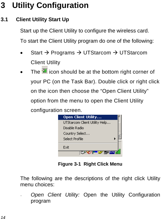
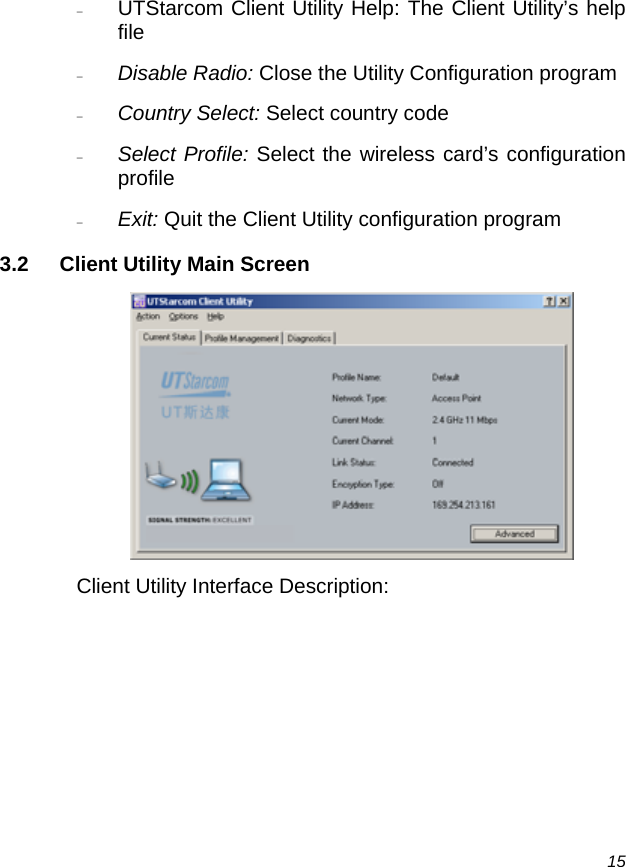
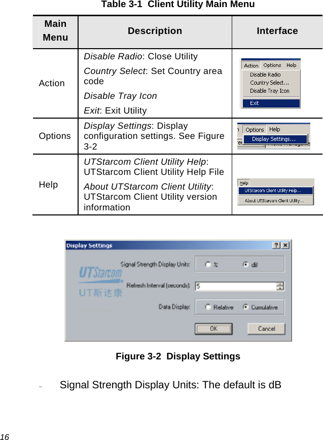
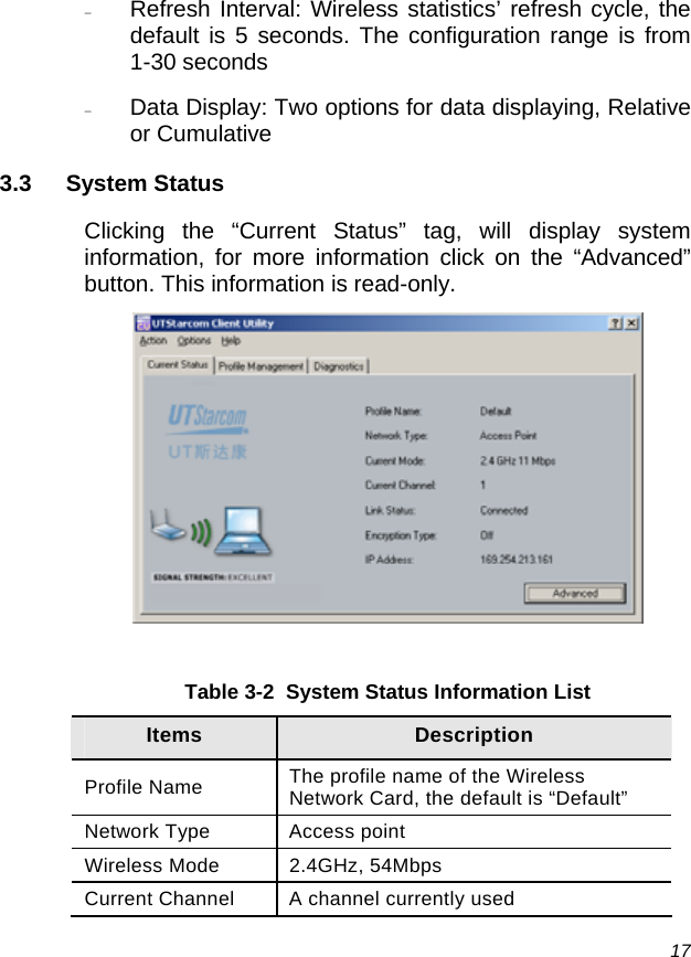
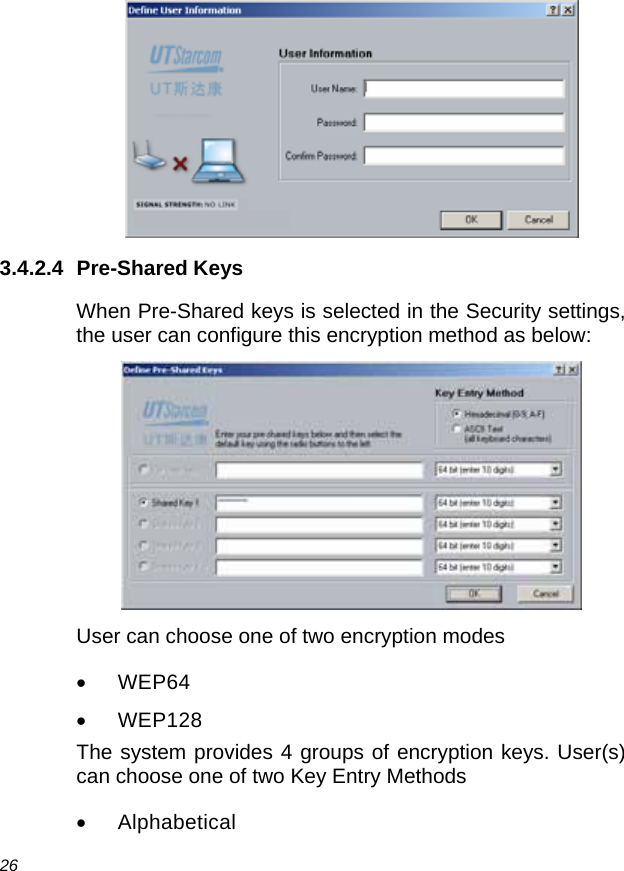
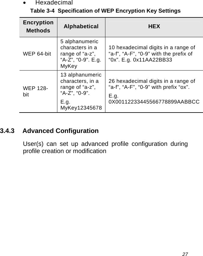
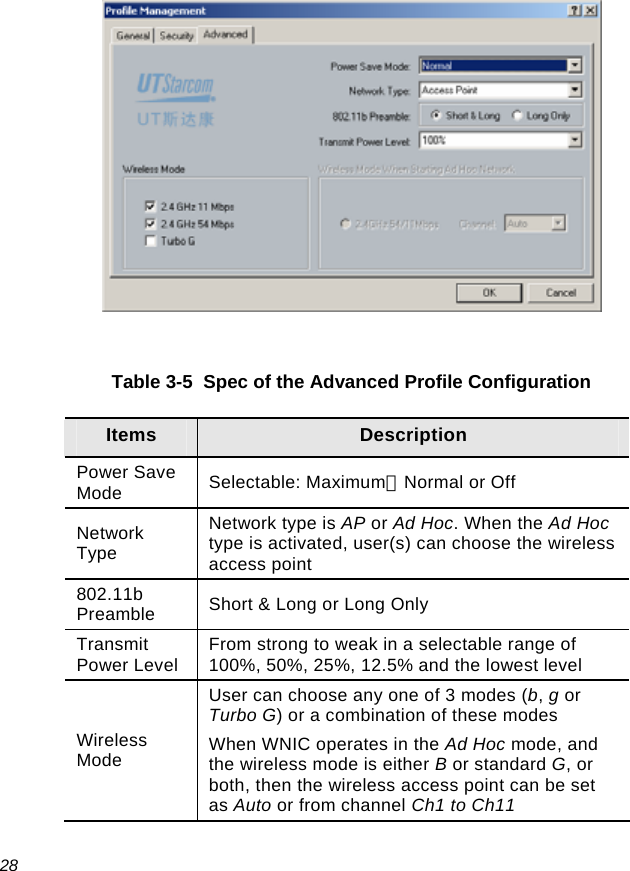
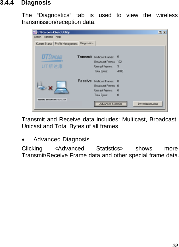
UTStarcom Telecom Co., Ltd. 802.11 b/g Wireless LAN PCMCIA Card
UserManual.wiki
>
UTStarcom Telecom
>
21690032 2010 User Manual
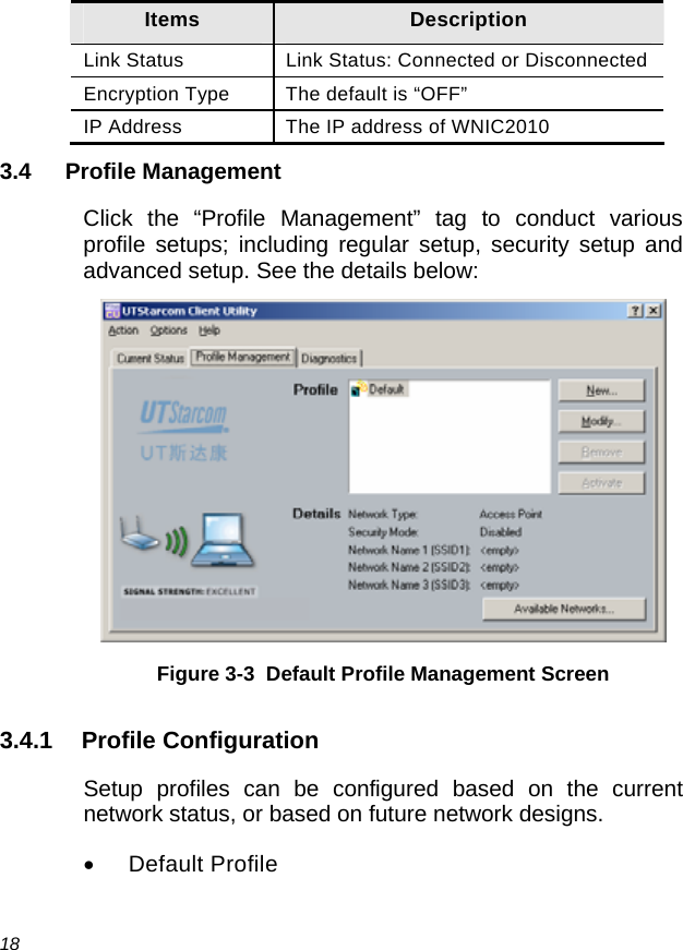
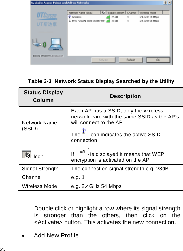
User Manual
Navigation menu
Upload a User Manual
Namespaces
Wiki Guide
HTML
PDF
Info
Views
User Manual
Discussion / Help
Navigation