UTStarcom Telecom 21690032-2010 802.11 b/g Wireless LAN PCMCIA Card User Manual
UTStarcom Telecom Co., Ltd. 802.11 b/g Wireless LAN PCMCIA Card
User Manual

1
WIRELESS NETWORK CARD
USER GUIDE
WNIC2010
2
Copyright © 2003, UTStarcom, Inc. All rights reserved. No part of this documentation may be
reproduced in any form or by any means or used to make any derivative work (such as translation,
transformation, or adaptation) without prior written permission from UTStarcom, Inc.
UTStarcom, Inc. reserves the right to revise this documentation and to make changes in content from
time to time without obligation on the part of UTStarcom, Inc. to provide notification of such revision or
change.
UTStarcom, Inc. provides this documentation without warranty of any kind, either implied or expressed,
including, but not limited to, the implied warranties of merchantability and fitness for a particular purpose.
UTStarcom may make improvements or changes in the product(s) and/or the program(s) described in
this documentation at any time.
UNITED STATES GOVERNMENT LEGENDS:
If you are a United States government agency, then this documentation and the software described
herein are provided to you subject to the following:
United States Government Legend: All technical data and computer software is commercial in nature
and developed solely at private expense. Software is delivered as Commercial Computer Software as
defined in DFARS 252.227-7014 (June 1995) or as a commercial item as defined in FAR 2.101(a) and
as such is provided with only such rights as are provided in UTStarcom's standard commercial license
for the Software. Technical data is provided with limited rights only as provided in DFAR 252.227-7015
(Nov 1995) or FAR 52.227-14 (June 1987), whichever is applicable. You agree not to remove or deface
any portion of any legend provided on any licensed program or documentation contained in, or delivered
to you in conjunction with, this User Guide.
UTStarcom, the UTStarcom logo, PAS, mSwtich, Airstar, WACOS, Netman, Total Control, and
CommWorks are registered trademarks of UTStarcom, Inc. and its subsidiaries. The UTStarcom name,
Airstar, AN-2000, WACOS, Netman and the CommWorks logo are trademarks of UTStarcom, Inc. and
its subsidiaries.
Intel and Pentium are registered trademarks of the Intel Corporation or its subsidiaries in the United
States and other countries. Microsoft, Windows, Windows NT, and NetMeeting are registered
trademarks of Microsoft Corporation. Sun, Java, and Solaris are trademarks or registered trademarks of
Sun Microsystems, Inc. Oracle is a registered trademark of Oracle Corporation. HP, HP-UX, and HP
Openview are trademarks or registered trademarks of the Hewlett-Packard Company.
Other brand and product names may be registered trademarks or trademarks of their respective holders.

3
UTSTARCOM MANUAL PRECAUTIONS
(FCC)
Federal Communications Commission (FCC) Requirements,
Part 15
This equipment has been tested and found to comply with
the limits for a class B digital device, pursuant to part 15 of
the FCC Rules. These limits are designed to provide
reasonable protection against harmful interference in a
residential installation.
This equipment generates, uses and can radiate radio
frequency energy and, if not installed and used in
accordance with the instructions, may cause harmful
interference to radio communications. However, there is no
guarantee that interference will not occur in a particular
installation. If this equipment does cause harmful
interference to radio or television reception, which can be
determined by turning the equipment off and on, the user is
encouraged to try to correct the interference by one or
more of the following measures:
• Reorient or relocate the receiving antenna.
• Increase the separation between the equipment and
receiver.
• Connect the equipment into an outlet on a circuit
different from that to which the receiver is connected.
• Consult the dealer or an experienced radio/TV
technician for help.
4
The users manual or instruction manual for an intentional
or unintentional radiator shall caution the user that changes
or modifications not expressly approved by the party
responsible for compliance could void the user's authority
to operate the equipment.
IMPORTANT NOTE (CO-LOCATED OPERATION)
FCC RF Radiation Exposure Statement: This equipment
complies with FCC RF radiation exposure limits set forth for
an uncontrolled environment. This device and its antenna
must not be co-located or operating in conjunction with any
other antenna or transmitter.

5
UTSTARCOM MANUAL PRECAUTION (CE)
R&TTE Regulatory statement
European standards dictate maximum radiated transmit
power of 100mW EIRP and frequency range 2.400-
2.4835GHz; In France, the equipment must be restricted to
the 2.4465-2.4835GHz frequency range and must be
restricted to indoor use.
CE Declaration of Conformity
For the following equipment: Wireless LAN Card
!
098
4
Is herewith confirmed to comply with the requirements set
out in the Council Directive on the Approximation of the
Laws of the Member States relating to Electromagnetic
Compatibility (89/336/EEC), Low-voltage Directive
(73/23/EEC) and the Amendment Directive (93/68/EEC),
the procedures given in European Council Directive
99/5/EC and 89/3360EEC.
The equipment was passed. The test was performed
according to the following European standards:
• EN 300 328-2 V.1.2.1 (2001-12)
• EN 301 489-1 V.1.4.1 (2002-04) / EN 301 489-17
V.1.2.1 (2002-04)
• EN 50371: 2002
• EN 60950: 2000
i
Table of Contents
UTSTARCOM MANUAL PRECAUTIONS (FCC)..................... 3
Federal Communications Commission (FCC) Requirements, Part 15 ... 3
IMPORTANT NOTE (CO-LOCATED OPERATION) .............................. 4
MPE Statement (Safety Information)......................錯誤! 尚未定義書籤。
Safety Information ..................................................錯誤! 尚未定義書籤。
UTSTARCOM MANUAL PRECAUTION (CE).......................... 5
R&TTE Regulatory statement ................................................................ 5
CE Declaration of Conformity................................................................. 5
1 Overview ........................................................................... 1
1.1 List of Box Contents ................................................................... 1
1.2 System Requirements................................................................ 1
2 Software Installation/Removal ........................................ 3
2.1 Installation on a Windows 2000, 98 or ME System .................... 3
2.2 Installation on a Windows XP System........................................ 7
2.3 Remove the UTStarcom Applications and Its Driver ................ 11
3 Utility Configuration....................................................... 14
3.1 Client Utility Start Up ................................................................ 14
3.2 Client Utility Main Screen ......................................................... 15
3.3 System Status .......................................................................... 17
3.4 Profile Management ................................................................. 18
3.4.1 Profile Configuration......................................................... 18
3.4.2 Security Configuration ...................................................... 21
3.4.3 Advanced Configuration ................................................... 27
ii
3.4.4 Diagnosis.......................................................................... 29
4 Trouble Shooting............................................................ 31
4.1 Open WMI Namespace Problem.............................................. 31
5 Technical Specification ................................................. 32
6 Glossary.......................................................................... 35
iii
List of Figures
Figure 3-1 Right Click Menu ..........................................................14
Figure 3-2 Display Settings............................................................16
Figure 3-3 Default Profile Management Screen ............................18
iv
List of Tables
Table 3-1 Client Utility Main Menu.................................................16
Table 3-2 System Status Information List......................................17
Table 3-3 Network Status Display Searched by the Utility ............20
Table 3-4 Specification of WEP Encryption Key Settings..............27
Table 3-5 Spec of the Advanced Profile Configuration..................28

1
1 Overview
WNIC2010 is an 802.11b/g compliant wireless PCMCIA
network card with data rates up to 54Mbps . It utilizes WPA
(Wireless Protected Access) technology to enhance
network security. Its bus interface is 32-bit miniPCI V1.0.
The wireless network card can either be used on a
computer by itself, or it can be used in conjunction with the
UTStarcom model AP WA3001-P access point to increase
performance.
1.1 List of Box Contents
Before installing and using the wireless network card,
check the contents in the box. If you find anything missing
or if the documentation set is incomplete, contact your local
dealer immediately. The following accessories ship with the
product:
One CD containing the WNIC2010 driver and Utility
Installation program
One WNIC2010 wireless network card
1.2 System Requirements
To ensure the proper installation and operation of the
network card, please make sure that the system
environment complies with the following requirements:
• Notebook computer includes:
− 32-bit card bus slot (or desktop with PCMCIA adapter)
- 32M RAM or more
− 300MHz processor or higher
2
• Operating System’s Supported:
- Microsoft Windows 2000
- Windows 98 SE
- Windows XP
- Windows ME

3
2 Software Installation/Removal
2.1 Installation on a Windows 2000, 98 or ME System
This section describes the installation steps on a PC for the
first time only.
Quick Setup Steps: Run the installation program Æ Insert
the WNIC2010 wireless network card Æ Reboot the
System
Detailed Setup Steps: (Note: The following example is for
a computer running Windows 2000):
Step 1: Installing the network card driver and the
UTStarcom applications.
1. Run the setup program “UTStarcom Installer.exe” in
the CD to start the InstallShield Wizard
2. When the opening installation screen appears Click
<Next>
3. The License Agreement screen will appear.
Carefully read the agreement and if you agree then
choose “I accept…”, then click <Next>. The
installation Setup Type selection window will appear
as follows:
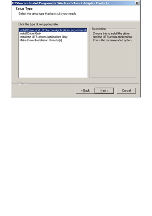
4
4. Choose a setup type. Install Driver and UTStarcom
Applications is the recommended option.
5. Click <Next>
6. Select a path for the installation, then click <Next>
7. Next the “Select Program Folder” screen will appear.
Choose an existing program folder name or create a
new one. This is the program name that will be
created on your Start>Programs menu. Then click
<Next>.
Note: If there was a previous installation of any
UTStarcom Applications, please close those UTStarcom
Applications.
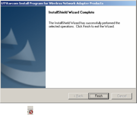
5
8. Installation will begin. When the installation is
completed, the following window will be displayed,
then click on the <Finish> button
9. Now, the icon is displayed on the Task Bar, which
is usually located at the bottom-right corner of the
PC screen.
Step 2: Insert the WNIC2010 wireless network card into the
computer’s PCMCIA card slot.
The following prompt will appear:
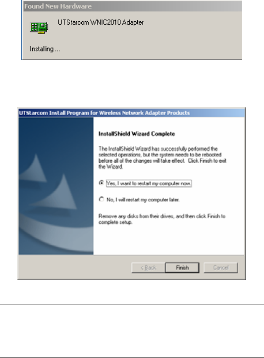
6
Step 3: When the previous prompt disappears, the Network
Adapter’s Driver installation is complete. Reboot the PC to
enable the wireless network card driver.
Note: The Microsoft Authentication window may appear
during the installation, click <Yes>, and the window will
disappear and installation will continue.
7
2.2 Installation on a Windows XP System
This section describes the installation steps on a PC for the
first time only.
Quick Setup Steps: Run the installation program Æ
Prompt to reboot the system Æ Insert the WNIC2010
wireless network card Æ On Windows XP systems the
network card will automatically install.
Detailed Setup Steps:
Step 1: Install the network card driver and the UTStarcom
applications.
10. Run the setup program “UTStarcom Installer.exe” in
the CD to start the InstallShield Wizard
11. When the opening screen appears, Click <Next>
12. The License Agreement screen will appear.
Carefully read the agreement and if you agree then
choose “I accept…”, then click <Next>. The
installation “Setup Type” selection window will
appear as shown below:
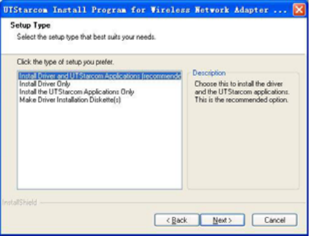
8
13. Chose a setup type. The “Install Driver and
UTStarcom Applications” is the recommended option.
Then Click <Next>
14. Select a path for the installation, and click <Next>
15. The “Select Program Folder” screen will appear.
Choose an existing program folder name or create a
new one. This is the program name that will be
created on your Start>Programs menu. Then click
<Next>.
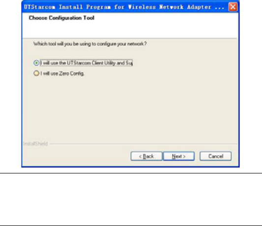
16. In the following screen, it is recommended to select
“I will use the UTStarcom Client Utility” option. If you
select “I will use Zero Config” option, then some
features will not be available.
9
Note: If there was a previous installation of any
UTStarcom Applications, please close those UTStarcom
Applications.
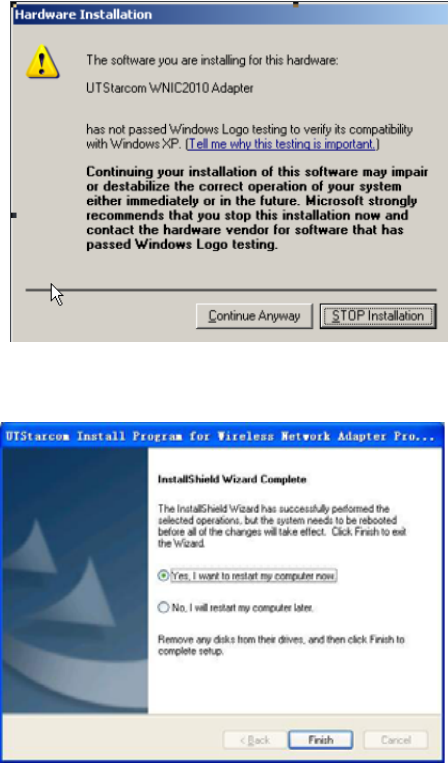
17. The installation will start. During the installation, the
following window will appear, then click <Continue
Anyway>
10
18. After the installation is completed, the following
window will be displayed. Then click <Finish>
11
19. If you selected “No, I will restart my computer later”,
then the icon will appear on the Task Bar, this is
usually located at the bottom-right corner of the PC
screen. If you selected “Yes, I want to restart my
computer now”, then continue on Step 2.
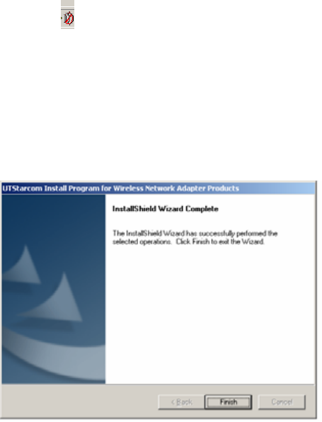
Step 2: Insert the wireless network card WNIC2010 into the
PC. The system will automatically complete the installation
of the wireless network card driver, and display the
following window. Then click <Finish>
2.3 Remove the UTStarcom Applications and Its Driver
If you want to remove the UTStarcom Applications and the
wireless network card driver, please use InstallShield
Wizard provided. Follow the steps below:
12
20. Run the setup program “UTStarcom Application”
from the CD to start the InstallShield Wizard
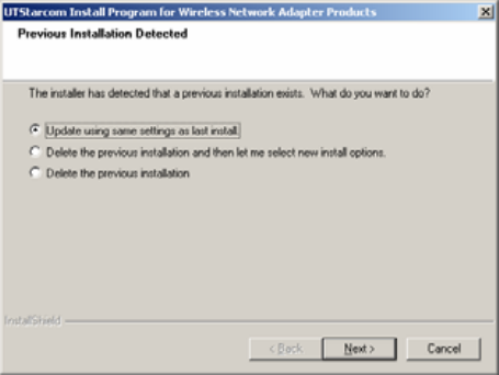
21. The system automatically checks the status of the
WNIC2010 installation and displays the list of
operations.
22. Select “Delete the previous installation” to confirm
previous installation removal, and then click <Next>.
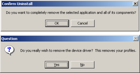
23. The following two dialogue boxes will display. The
first dialogue box asks the user to confirm their
intention of removing the selected application and all
of its components. Click <OK>.
24. The second dialogue box asks the user to confirm if
they want to remove the network card driver and
related profiles. Click <Yes>.
13
25. When the removal is complete, the InstallShield
Wizard completion window is displayed, then click
<Finish>.
14
3 Utility Configuration
3.1 Client Utility Start Up
Start up the Client Utility to configure the wireless card.
To start the Client Utility program do one of the following:
• Start Æ Programs Æ UTStarcom Æ UTStarcom
Client Utility
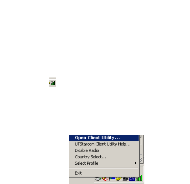
• The icon should be at the bottom right corner of
your PC (on the Task Bar). Double click or right click
on the icon then choose the “Open Client Utility”
option from the menu to open the Client Utility
configuration screen.
Figure 3-1 Right Click Menu
The following are the descriptions of the right click Utility
menu choices:
− Open Client Utility: Open the Utility Configuration
program
15
− UTStarcom Client Utility Help: The Client Utility’s help
file
− Disable Radio: Close the Utility Configuration program
− Country Select: Select country code
− Select Profile: Select the wireless card’s configuration
profile
− Exit: Quit the Client Utility configuration program
3.2 Client Utility Main Screen
Client Utility Interface Description:
16
Table 3-1 Client Utility Main Menu
Main
Menu Description Interface
Action
Disable Radio: Close Utility
Country Select: Set Country area
code
Disable Tray Icon
Exit: Exit Utility
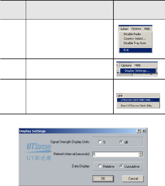
Options Display Settings: Display
configuration settings. See Figure
3-2
Help
UTStarcom Client Utility Help:
UTStarcom Client Utility Help File
About UTStarcom Client Utility:
UTStarcom Client Utility version
information
Figure 3-2 Display Settings
− Signal Strength Display Units: The default is dB
17
− Refresh Interval: Wireless statistics’ refresh cycle, the
default is 5 seconds. The configuration range is from
1-30 seconds
− Data Display: Two options for data displaying, Relative
or Cumulative
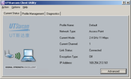
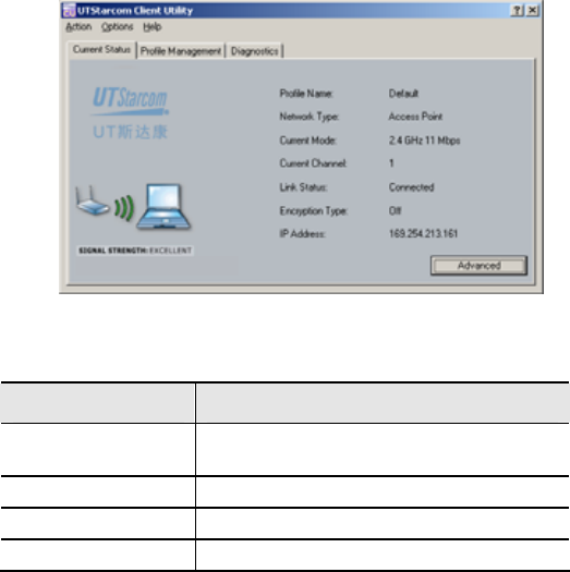
3.3 System Status
Clicking the “Current Status” tag, will display system
information, for more information click on the “Advanced”
button. This information is read-only.
Table 3-2 System Status Information List
Items Description
Profile Name The profile name of the Wireless
Network Card, the default is “Default”
Network Type Access point
Wireless Mode 2.4GHz, 54Mbps
Current Channel A channel currently used
18
Items Description
Link Status Link Status: Connected or Disconnected
Encryption Type The default is “OFF”
IP Address The IP address of WNIC2010
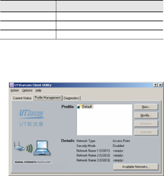
3.4 Profile Management
Click the “Profile Management” tag to conduct various
profile setups; including regular setup, security setup and
advanced setup. See the details below:
Figure 3-3 Default Profile Management Screen
3.4.1 Profile Configuration
Setup profiles can be configured based on the current
network status, or based on future network designs.
• Default Profile

19
After installation the system automatically creates a default
profile that will be used when the WNIC2010 wireless card
and UTStarcom application starts up. The application will
search for an AP with a stronger signal and the WNIC2010
will automatically establish a wireless connection with this
AP.
Note: The user can identify the currently used AP by
checking for the icon located in front of the SSID field
of the selected AP through clicking on the “Available
Networks” button.
The user also can configure the default profile and specify
the SSID. Each profile can have at the most 3 SSIDs
assigned. After assigning the SSID(s), the WNIC2010 will
search for the best wireless connection and switch to it
automatically. When the connection’s signal strength and
stability are equal, the WNIC2010 will choose the SSID
based on the priority. ie. SSID1 > SSID2 > SSID 3. If SSID1
is null, the system will choose the link with a better
performance instead of the priority mentioned above.
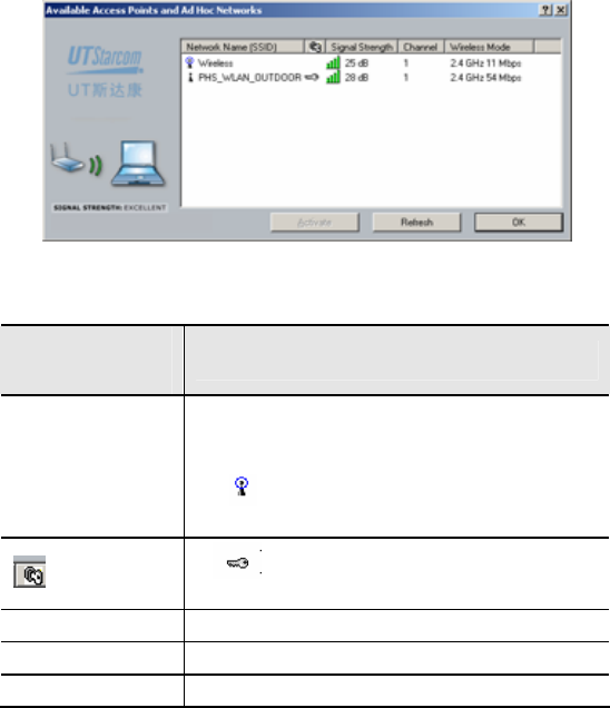
• Check Network Status
- Click <Available Networks>, the system will display all
AP information found by the Client Utility application.
20
Table 3-3 Network Status Display Searched by the Utility
Status Display
Column Description
Network Name
(SSID)
Each AP has a SSID, only the wireless
network card with the same SSID as the AP’s
will connect to the AP.
The Icon indicates the active SSID
connection
: Icon If is displayed it means that WEP
encryption is activated on the AP
Signal Strength The connection signal strength e.g. 28dB
Channel e.g. 1
Wireless Mode e.g. 2.4GHz 54 Mbps
- Double click or highlight a row where its signal strength
is stronger than the others, then click on the
<Activate> button. This activates the new connection.
• Add New Profile
21
There are two ways to add new profiles in the system
- Click <New> to enter “Profile Management” screen,
then specify a profile name and a SSID
- On the <Available Networks> screen, double click one
of the displayed SSIDs to open the “Add New Profile”
screen
• Modify Profile
- On the “Profile Management” tab, select a profile to be
modified. Click the <modify> button to enter Profile
Management screen.
• Remove Profile
- Choose an inactive profile and Click the <Remove>
button
- Note: The currently active profile cannot be removed
• Activate Profile – To activate a new profile do one of
the following.
- On the “Profile Management” tab, select a profile to be
used. Click the <Activate> button to enable it.
- Or, double click a profile to be activated
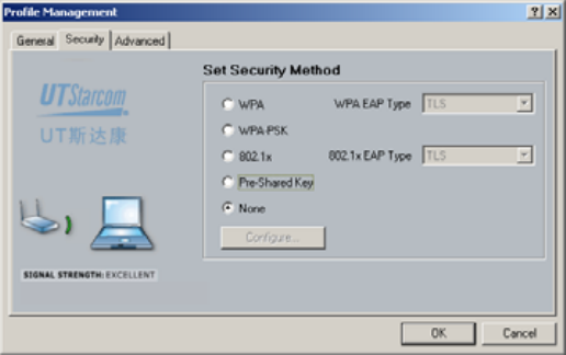
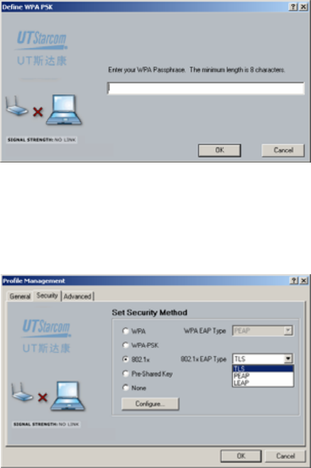
3.4.2 Security Configuration
The user can setup security for a Profile during profile
creation, or modification.
22
The default security setting is “None”. The system provides
the following security methods.
• WPA
• WPA-PSK
• 802.1x
• Pre-Shared Key
3.4.2.1 WPA
− When the WPA EAP option is “TLS”, the system will
display a prompt as below:
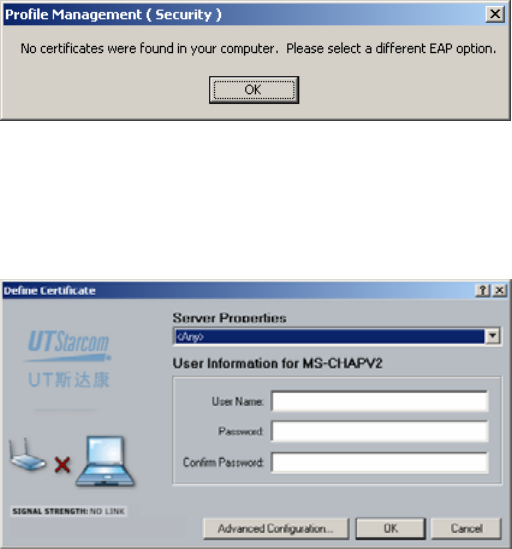
23
The WPA EAP option can only be used when a related
certificate is installed on the PC
− When the WPA EAP option is “PEAP”, the system will
display the following window when “Configure…” is
clicked:
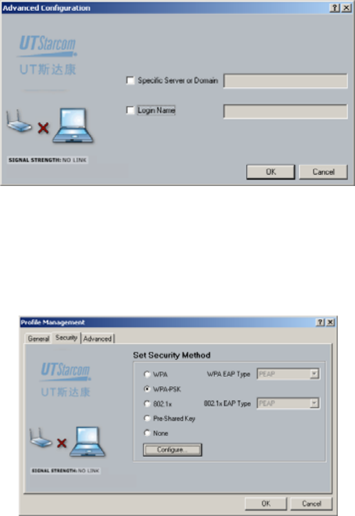
The user needs to select a Certificate Server from the
Server Property drop down list. Then enter a user name
and password. The user can specify a Server or its Domain
name and login name by clicking on the <Advanced
Configuration…> button.
24
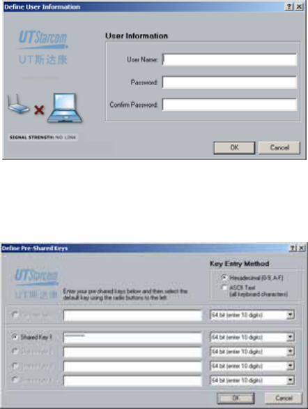
3.4.2.2 WPA-PSK
Only one passphrase is required for any set of WLAN
nodes (wireless access base station, wireless router,
client’s wireless network card, bridge etc). The client will
receive access privileges if the passphrase matches. The
WPA-PSK method is very common in SOHO
After selecting “WPA-PSK”, click on the <Configure…>
button to enter your WPA passphrase.
25
The minimum WPA passphrase length is 8 characters
3.4.2.3 802.1x
When 802.1x authentication mode is activated, the
selectable EAP options are: TLS, PEAP and LEAP
For TLS and PEAP, refer to section 3.4.2.1 for details. The
following describes the LEAP configuration. Setting the
User Name and Password is the only information required.
26
3.4.2.4 Pre-Shared Keys
When Pre-Shared keys is selected in the Security settings,
the user can configure this encryption method as below:
User can choose one of two encryption modes
• WEP64
• WEP128
The system provides 4 groups of encryption keys. User(s)
can choose one of two Key Entry Methods
• Alphabetical

27
• Hexadecimal
Table 3-4 Specification of WEP Encryption Key Settings
Encryption
Methods Alphabetical HEX
WEP 64-bit
5 alphanumeric
characters in a
range of “a-z”,
“A-Z”, “0-9”. E.g.
MyKey
10 hexadecimal digits in a range of
“a-f”, “A-F”, “0-9” with the prefix of
“0x”. E.g. 0x11AA22BB33
WEP 128-
bit
13 alphanumeric
characters, in a
range of “a-z”,
“A-Z”, “0-9”.
E.g.
MyKey12345678
26 hexadecimal digits in a range of
“a-f”, “A-F”, “0-9” with prefix “ox”.
E.g.
0X00112233445566778899AABBCC
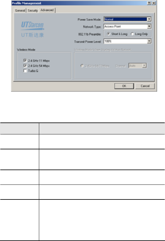
3.4.3 Advanced Configuration
User(s) can set up advanced profile configuration during
profile creation or modification
28
Table 3-5 Spec of the Advanced Profile Configuration
Items Description
Power Save
Mode Selectable: Maximum,Normal or Off
Network
Type
Network type is AP or Ad Hoc. When the Ad Hoc
type is activated, user(s) can choose the wireless
access point
802.11b
Preamble Short & Long or Long Only
Transmit
Power Level From strong to weak in a selectable range of
100%, 50%, 25%, 12.5% and the lowest level
Wireless
Mode
User can choose any one of 3 modes (b, g or
Turbo G) or a combination of these modes
When WNIC operates in the Ad Hoc mode, and
the wireless mode is either B or standard G, or
both, then the wireless access point can be set
as Auto or from channel Ch1 to Ch11
29
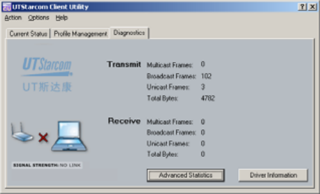
3.4.4 Diagnosis
The “Diagnostics” tab is used to view the wireless
transmission/reception data.
Transmit and Receive data includes: Multicast, Broadcast,
Unicast and Total Bytes of all frames
• Advanced Diagnosis
Clicking <Advanced Statistics> shows more
Transmit/Receive Frame data and other special frame data.
30
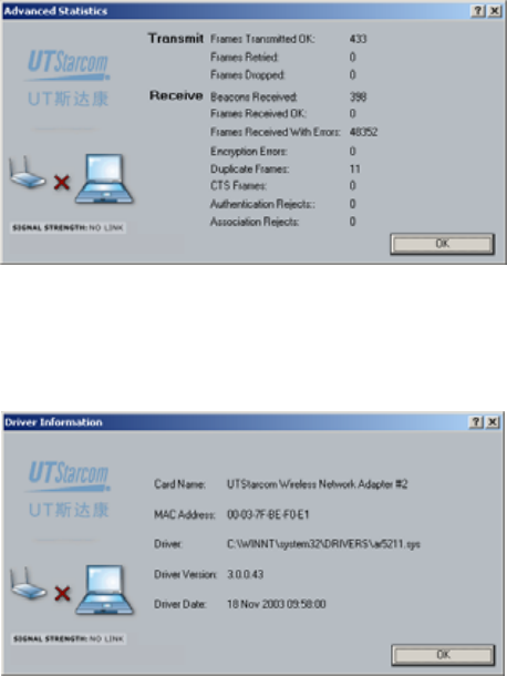
• Driver Information
To view the current wireless network card driver
information, click the <Driver Information> button and the
following screen will be displayed
The Driver Information screen displays the following
wireless network card’s information: Card Name, MAC
Address, Driver file location, Driver Version and release
date.

31
4 Trouble Shooting
4.1 Open WMI Namespace Problem
• Problem description
In some Win98 systems, when user starts the “Client Utility
Configuration”, a popup message will be displayed as
below
“Unable to open WMI namespace. WMI initialization failed.
Cannot proceed further.”
• Solution
Run wmi9x.exe from the installation CD to install the WMI
namespace.

32
5 Technical Specification
Model WNIC2010
Description 2.4GHz(802.11g) 108Mbps CardBus
wireless network card
Modulation technique
-IEEE 802.11
-IEEE 802.11b
-IEEE 802.11g
Interface Host
Interface 32-bit CardBus ( or PC Card 7.1)
Wireless
Transfer
Rate
Super G™: 108Mbps
802.11g: 54, 48, 36, 24, 18, 12, 9,
6Mbps
802.11b: 11, 5.5, 2, 1Mbps
Security
64, 128, 152 bits WEP
802.1X (EAP-TLS, PEAP, LEAP)
WPA and WPA-PSK(TKIP,AES)
WAPI
Receiving
sensitivity
-73dBm @ 108Mbps, PER < 8%,
OFDM
-73dBm @ 54Mbps, PER < 8%,
ODFM
-90dBm @ 11Mbps, PER < 8%,
CCK
-92dBm @ 6Mbps, PER < 8%,
OFDM
-95dBm @ 1Mbps, PER < 8%,
DBPSK
Characte
ristics
Frequency
range 2.4GHz∼2.4835GHz

33
Model WNIC2010
Output
power Typical: 20mW (13.2dBm) (Max)
Operating
System
support Windows 98SE,Me,2000,XP
Operation
mode Ad-Hoc and Infrastructure
Network
manageme
nt Utility
Operation
voltage 3.3VDC±5%
Electric
performa
nce Current
consumptio
n
- Transmission mode < 550mA @
3.3VDC
- Receive mode <350mA @3.3VDC
- Idle mode <225mA @3.3VDC
- Radio disabled mode <10mA
@3.3VDC
Dimension 118mm (L) x 54mm (W) x 5mm (H)
Weight About 50g
Internal
antenna Dual Antenna
Physical
character
istic
LED
indicator
- WLAN activity indicator
- WLAN radio status indicator
Operationa
l
temperatur
e
0℃~ 70℃
Environm
ent
attributes Storage
temperatur
e -25℃~ 75℃
MTBF >30000 hours

34
Model WNIC2010
Security
authentic
ation
- GB9254 B grade
- FCC part 15 B grade (USA)
- CE (Europe)
Compatib
ility
- Wi-Fi WECA compliant
- WHQL Microsoft XP, Me, 2K compliant
- FAA S/W audio On/Off supported

35
6 Glossary
AC Access Controller
AS Authentication Server
CLI Command Line Interface
DHCP Dynamic Host Configuration Protocol
EAP Extensible Authentication Protocol
IEEE Institute of Electrical and Electronics
Engineering
LAN Local Area Network
MAC Media Access Control
MD5 Message Digest Algorithm 5
MIB Management Information Base
MII Media Independent Interface
NAS Network Access Server
NMS Network Management System
OAM Operation administration and maintenance
PD Powered Device
PoE Power over Ethernet
PPPoE PPP over Ethernet
PSE Power Sourcing Equipment

36
SNMP Simple network management protocol
WEP Wired Equivalent Privacy
WLAN Wireless Local Area Network

Copyright © 2004, UTStarcom, Inc. All rights reserved.
May not be reproduced without prior written permission.
China
Building 3,
Yile Industrial Park
No. 129, Wenyi Road,
Hangzhou 310012 PRC
+86-21-63910500
India
805 Signature Towers B,
South City I
Gurgaon,
Haryana 122001
+91-124-2805045
Japan
TT-2 Building 8th Floor,
3-8-1 Nihonbashi
Ningyo-cho, Chuo-ku, Tokyo,
Japan
+81-3-5643-8070
Europe
Campus Kronberg 7,
61476 Kronberg
Germany
Latin America
2801 SW 149th Ave
Suite 100
Miramar, FL 33027, USA
UTStarcom, Inc. USA
1275 Harbor Bay Parkway Alameda, CA 94502, USA
Tel. 510-864-8800 Fax. 510-864-8802