UTStarcom Telecom 3001P Access Point User Manual
UTStarcom Telecom Co., Ltd. Access Point Users Manual
UserManual.wiki
>
UTStarcom Telecom
>
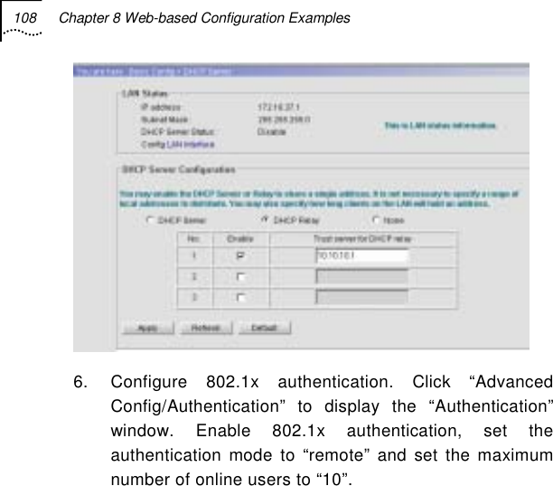
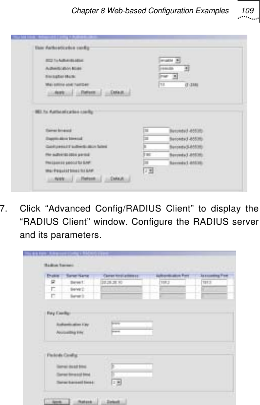
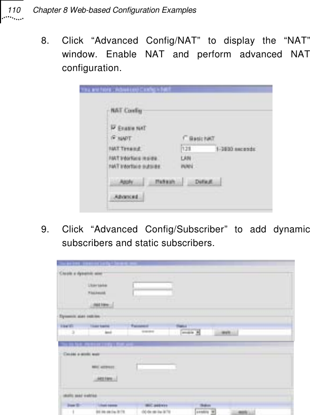
3001P User Manual
Users Manual
Navigation menu
Upload a User Manual
Namespaces
Wiki Guide
HTML
PDF
Info
Views
User Manual
Discussion / Help
Navigation


![118 Chapter 9 CLI Command Set Clear Use this command to clear the screen. It can be used at any configuration level. Syntax: clear Access level: 0 End Use this command to return to the privileged EXEC mode from any CLI level except EXEC level. This command can be used at any configuration level except EXEC level. Syntax: end Access level: 0 Exit Use this command to return one level back. Use “exit all” to return to EXEC level. This command can be used at any configuration level. Syntax: exit [all] Access level: 0](https://usermanual.wiki/UTStarcom-Telecom/3001P/User-Guide-506514-Page-147.png)
![124 Chapter 9 CLI Command Set Clear ARP Use this command to reset the ARP table. Syntax: clear arp Access level: 2 Explanation: Use this command to clear the ARP table or delete all dynamic entries. Clear DHCP Binding Use this command to delete one or all automatic address binding(s) from the Dynamic Host Configuration Protocol (DHCP) Server database. Syntax: clear dhcp binding [ip-address] Possible value: ip-address: The address of the binding to be cleared Default value: clear all bindings Access level: 2 Explanation: Use this command to clear DHCP server IP address bind table.](https://usermanual.wiki/UTStarcom-Telecom/3001P/User-Guide-506514-Page-153.png)
![Chapter 9 CLI Command Set 125 Clear DHCP Statistics Use this command to reset all Dynamic Host Configuration Protocol (DHCP) Server counters or Relay counters. Syntax: clear dhcp statistics [relay | server] Default value: Relay and server’s statistics Access level: 2 Clear Dot1x Statistics Use this command to reset all 802.1x counters. Syntax: clear dot1x statistics Access level: 2 Explanation: Use this command to clear DOT1X statistics. Clear RADIUS Use this command to reset all radius counters. Syntax: clear radius Access level: 2](https://usermanual.wiki/UTStarcom-Telecom/3001P/User-Guide-506514-Page-154.png)

![Chapter 9 CLI Command Set 131 DHCP-Client Trust Use this command to set the trusted DHCP server IP addresses. (Up to 5) Syntax: [no] dhcp-client trust <ip-address> Possible value: ip-address: IP address of DHCP server Access level: 2 DHCP-Pool Use the dhcp-pool global configuration command to configure Dynamic Host Configuration Protocol (DHCP) address pool on the DHCP Server and enter the domain’s DHCP pool configuration mode. Use the no form of this command to remove the address pool. Syntax: [no] dhcp-pool Default value: DHCP address pools are not configured. Access level: 2 DHCP-Server Host Use this command to set the DHCP server’s IP address when DHCP relay is enabled; use the no form to delete the server.](https://usermanual.wiki/UTStarcom-Telecom/3001P/User-Guide-506514-Page-160.png)
![132 Chapter 9 CLI Command Set Syntax: [no]dhcp-server host <IPaddress> (Up to 3) Possible value: ip address Access level: 2 Dot1x Authentication Enable / Disable Use this command to enable or disable the DOT1X authentication function. Syntax: dot1x authentication {enable|disable} <port> Possible value: Port: lan, wlan1, wlan2 Default value: disable Access level: 2 Dot1x Authentication Mode Use this command to set the authentication mode for this AP. Syntax: dot1x authentication mode <port> <mode> no dot1x authentication mode <port> Possible value: Port: lan, wlan1, wlan2](https://usermanual.wiki/UTStarcom-Telecom/3001P/User-Guide-506514-Page-161.png)
![136 Chapter 9 CLI Command Set re-authentication attempts (re-authperiod) and automatic re-authentication. Syntax: dot1x re-authenticate <userid> Possible value: userid: 1-256 Access level: 2 Explanation: Use this command to manually initiate a re-authentication for a subscriber at once. Dot1x Re-Authentication Use this command to enable periodic re-authentication of the client. Use the no form of this command to return to the default setting. Configure the time period between periodic re-authentication attempts by using the dot1x re-authperiod command. Syntax: [no] dot1x re-authentication <userid> Possible value: userid: 1-256 Default value: Periodic re-authentication is disabled Access level: 2 Explanation: Use this command to set the periodic re-authentication status while the subscriber is online.](https://usermanual.wiki/UTStarcom-Telecom/3001P/User-Guide-506514-Page-165.png)
![144 Chapter 9 CLI Command Set ipaddr: This parameter identifies the destination IP address of the static route. mask: This parameter identifies the destination prefix mask of the static route. next-hop: This parameter identifies the IP address of the next hop that can be used to reach the network. Access level: 2 Isolation Use this command to set isolation between the subscribers. No parameter means to isolate all. Syntax: isolation [lan | lan-wlan | wlan ] Access level: 2 Load-Balance Enable/Disable Use this command to enable or disable the load balance. Syntax: load-balance {enable|disable} Access level: 2](https://usermanual.wiki/UTStarcom-Telecom/3001P/User-Guide-506514-Page-173.png)
![Chapter 9 CLI Command Set 145 Load-Balance Mode Use this command to set load-balance mode. Syntax: load-balance mode {user-base | flux-base} Default Value: user-base Access level: 2 MAC Age Time Use this command to set the aging period for all MAC address entries in the address table of the switch. Syntax: mac age time <value> Possible value: value: 10~65535 seconds Default value: 300 seconds Access level: 2 MAC Black-List Use this command to add/delete a MAC black list entry. The packets from the source MAC addresses will not be permitted to access the AP. Syntax: [no] mac black-list <mac-address>](https://usermanual.wiki/UTStarcom-Telecom/3001P/User-Guide-506514-Page-174.png)
![Chapter 9 CLI Command Set 147 NAT Interface Use this command to specify the interface attached to NAT. Syntax: nat interface {inside | outside} <lan | wan> Default value: inside: lan(downlink) outside: wan (uplink) Access level: 2 NAT Map Use this command to configure static entries of address mapping for basic NAT. Syntax: [no] nat map <local-ip> <global-ip> Possible value: local-ip: Private IP address inside NAT . global-ip: Global IP address outside NAT. Access level: 2](https://usermanual.wiki/UTStarcom-Telecom/3001P/User-Guide-506514-Page-176.png)
![148 Chapter 9 CLI Command Set NAT Mode Use this command to set NAT mode. Syntax: nat mode {napt|basic} Default value: napt Access level:2 NAT Pool Use this command to configure address pool for dynamic NAT. Syntax: [no] nat pool <start-ip> <ip-mask> Possible value: start-ip: Specifies the IP address at the beginning of the pool range. ip-mask: Specifies the network mask associated with the address pool. Access level: 2 NAT Redirect Use this command to configure static entry of host redirection for NAPT.](https://usermanual.wiki/UTStarcom-Telecom/3001P/User-Guide-506514-Page-177.png)
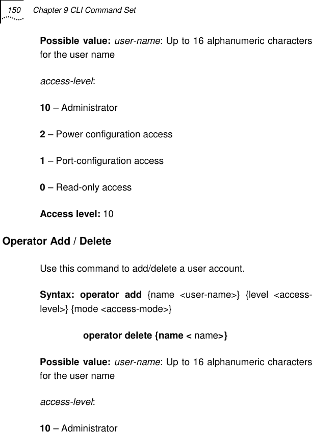
![Chapter 9 CLI Command Set 149 Syntax: [no] nat redirect <global-port> <local-ip> Possible value: global_port: Destination port number of incoming packets. local_ip: Private IP address to be redirected. Access level: 2 NAT Timeout Use this command to set the age timeout for all NAT entries. Syntax: nat timeout <secs> Possible value: secs: 1-3600 Default value: 120 Access level: 2 Operator Access level Use this command to change the user’s access level. Syntax: operator access level {name <user-name>} {level <access-level>}](https://usermanual.wiki/UTStarcom-Telecom/3001P/User-Guide-506514-Page-178.png)
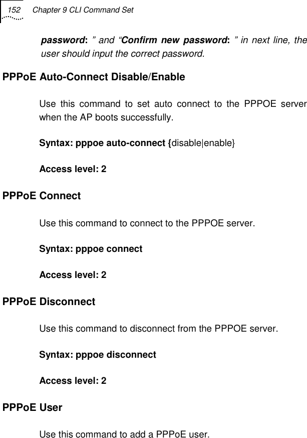
![Chapter 9 CLI Command Set 153 Syntax: pppoe user {name <name>} {password <pwd>} Possible value: name: up to 30 characters; pwd: up to 30 characters. Access level: 2 RADIUS-Acctserver {Enable | Disable} Use this command to enable/disable a designated accounting server. Syntax: radius-acctserver {enable | disable} [first | second | third] Access level: 2 RADIUS-Acctserver Host Use the radius-acctserver host global configuration command to specify a RADIUS accounting server host. Syntax: radius-acctserver host {first | second | third} <ip-address> no radius-acctserver host {first | second | third} Possible Value: ip-address: IP address of the RADIUS accounting server host.](https://usermanual.wiki/UTStarcom-Telecom/3001P/User-Guide-506514-Page-182.png)
![154 Chapter 9 CLI Command Set Access level: 2 RADIUS-Acctserver Info Use this command to set the designated accounting server’s parameter(s). Use the no form of this command to set the designated accounting server’s parameter(s) as default value(s). Syntax: radius-acctserver info {first | second | third} [acct-port <port-number>] [accounting-key {string}] [timeout <seconds >] [dead-time <minutes>] [retransmit <retries >] no radius-acctserver info {first | second | third} [acct-port] [accounting-key] [timeout] [dead-time] [retransmit] Possible Value: acct-port: 1-65535; default value: 1813 accounting-key {string}: string, default value: “” timeout: 1-16 seconds; default value: 5 seconds dead-time: 1-1440 minutes; default value: 5 minutes retransmit: 1-6; default value: 3 Access level: 2](https://usermanual.wiki/UTStarcom-Telecom/3001P/User-Guide-506514-Page-183.png)
![Chapter 9 CLI Command Set 155 RADIUS-Authserver {Enable | Disable} Use this command to enable/disable the designated authentication server. Syntax: radius-authserver {enable | disable} [first | second | third] Access level: 2 RADIUS-Authserver Extra Use this command to set authentication radius server’s additional attribute. Syntax: radius-authserver extra {first | second | third} [iapp|wpa] Possible value: iapp|wpa: keywords Access level: 2 RADIUS-Authserver Host Use the radius-authserver host global configuration command to specify a RADIUS authentication server host. The other parameters are default. Syntax: radius-authserver host {first | second | third} <ip-address>](https://usermanual.wiki/UTStarcom-Telecom/3001P/User-Guide-506514-Page-184.png)
![156 Chapter 9 CLI Command Set no radius-authserver host {first | second | third} Possible Value: ip-address: IP address of the RADIUS authentication server host. Access level: 2 RADIUS-Authserver Info Use this command to set the designated authentication server’s parameter(s). Use the no form of this command to set the designated authentication server’s parameter(s) as default value(s). Syntax: radius-authserver info {first | second | third} [auth-port <port-number>] [authentication-key <string>] [timeout <seconds >] [dead-time <minutes>] [retransmit <retries >] no radius-authserver info {first | second | third} [auth-port] [authentication-key] [timeout] [dead-time] [retransmit] Possible Value: auth-port: 1-65535; default value: 1812 authentication-key <string>:string; default value: “” timeout: 1-16 seconds; default value: 5 seconds dead-time: 1-1440 minutes; default value: 5 minutes](https://usermanual.wiki/UTStarcom-Telecom/3001P/User-Guide-506514-Page-185.png)
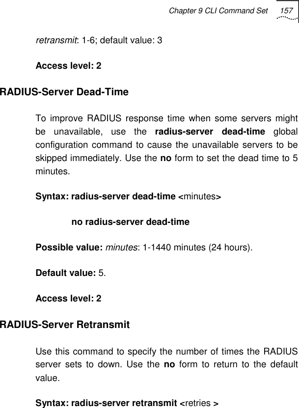
![158 Chapter 9 CLI Command Set no radius-server retransmit Possible Value: retries: 1-6 Default Value: 3 times Access level: 2 RADIUS-Server Timeout Use this command to set the interval a router waits for a server host to reply. Use the no form to restore the default value. Syntax: radius-server timeout <seconds > no radius-server timeout Possible Value: seconds: 1-16 Default: 5 seconds Access level: 2 SNMP Client Use this command to set SNMP client IP address. Syntax: snmp client <ipaddr> [mask] no snmp client < ip>](https://usermanual.wiki/UTStarcom-Telecom/3001P/User-Guide-506514-Page-187.png)

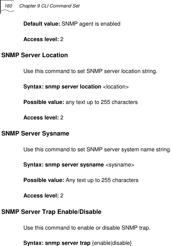
![Chapter 9 CLI Command Set 161 Possible value: N/A Default value: trap is enable Access level: 2 SNMP Server Trap Host Use this command to set SNMP trap host. Syntax: snmp server trap host <host-addr> [community <trap-community>] [port<trap-port>][version<v1|v2>] no snmp server trap host <host-addr> Default value: community :public Port:162 Version: v2 Static-MAC-Address Use this command to define or remove a MAC address in the static filtering database. Syntax: [no] static-mac-address <mac-address> {wan|lan|wlan} Possible value: mac-address: xx:xx:xx:xx:xx:xx Access level: 2](https://usermanual.wiki/UTStarcom-Telecom/3001P/User-Guide-506514-Page-190.png)
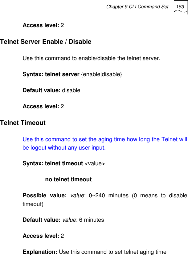
![162 Chapter 9 CLI Command Set Static-User Use this command to add or delete a static user. Syntax: static-user {mac <mac-addr>} no static-user {mac <mac-addr>} Access level: 2 Static-User Enable / Disable Use this command to enable or disable a static user. Syntax: static-user {mac <mac-addr>} <[enable]/[disable] Possible value: mac-addr: xx:xx:xx:xx:xx:xx Default value: disable Access level: 2 Telnet Client Use this command to set which IP address (subnet) can or cannot access the device via telnet. (UP TO 10) Syntax: telnet client <ip-address> [netmask] no telnet client <ip-address> [netmask]](https://usermanual.wiki/UTStarcom-Telecom/3001P/User-Guide-506514-Page-191.png)
![168 Chapter 9 CLI Command Set Syntax: webserver Access level: 2 Wireless-Port Use this command to enter the wireless card configuration level. Syntax: wireless-port <port> Possible value: ports: 1-2 Access level: 1 DHCP-pool Configuration Mode DNS-Server Use the dns-server DHCP pool configuration command to specify the Domain Name System (DNS) IP servers available to a Dynamic Host Configuration Protocol (DHCP) client. To remove the DNS server list, use the no form of this command. Syntax: dns-server <address> [address2] [address3].[address4] no dns-server](https://usermanual.wiki/UTStarcom-Telecom/3001P/User-Guide-506514-Page-197.png)
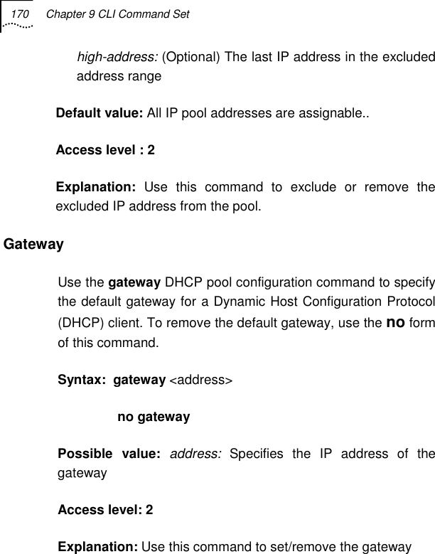
![Chapter 9 CLI Command Set 169 Possible value: address: Specifies the IP address of a DNS server. One IP address is required. The user can specify up to four addresses in one command line. address2...address4: (Optional) Specifies up to four addresses in the command line Default value: If DNS IP servers are not configured for a DHCP client, the client cannot correlate host names to the IP addresses. Access level : 2 Explanation: Use this command to set/remove DNS server(s). Excluded-Address Use the excluded-address global configuration command to specify IP addresses that a DHCP Server should not assign to DHCP clients. To remove the excluded IP addresses, use the no form of this command. (Up to 8) Syntax: excluded-address <low-address> [high-address] no excluded-address <low-address> [high-address] Possible value: low-address: The excluded IP address or first IP address in the excluded address range.](https://usermanual.wiki/UTStarcom-Telecom/3001P/User-Guide-506514-Page-198.png)
![Chapter 9 CLI Command Set 171 Lease Use the lease DHCP pool configuration command to configure the duration of the lease for an IP address that is assigned by a Dynamic Host Configuration Protocol (DHCP) Server to a DHCP client. To restore the default value, use the no form of this command. Syntax: lease {[[days <days>] [hours <hours>] [minutes <minutes>] ] | [ infinite]} no lease Possible value: days: Specifies the duration of the lease in numbers of days hours: Specifies the number of hours in the lease. A day’s value must be fed before configuring an hour’s value. minutes: Specifies the number of minutes in the lease. A day’s value and an hour’s value must be fed before configuring a minute’s value. Infinite: Specifies that the duration of the lease is unlimited Default value: One day Access level: 2](https://usermanual.wiki/UTStarcom-Telecom/3001P/User-Guide-506514-Page-200.png)
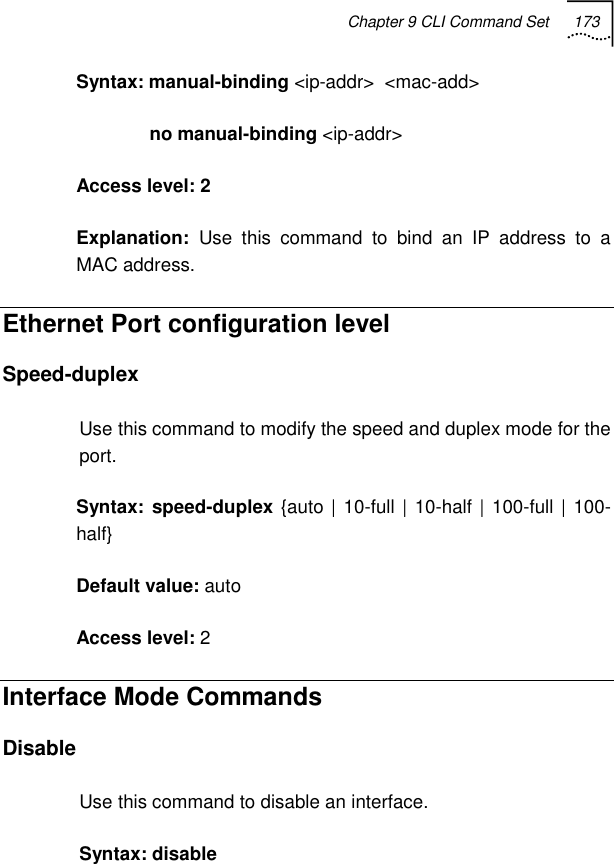
![172 Chapter 9 CLI Command Set Explanation: Use this command to set lease for an IP address that is assigned from the DHCP server. Network Use the network DHCP pool configuration command to configure the subnet number and mask for a Dynamic Host Configuration Protocol (DHCP) address pool on a DHCP Server. To remove the subnet number and mask, use the no form of this command. Syntax: [no] network <network-number> <mask > Possible value: network-number: The IP address of the DHCP address pool mask: The bit combination that renders which portion of the address of the DHCP address pool referring to the network or subnet and which part referring to the host. Access level: 2 Explanation: Use this command to set/remove the network for DHCP pool on a DHCP server. Manual-Binding Use this command to specify the IP address to a specific MAC address for a manual binding to a Dynamic Host Configuration Protocol (DHCP) client.](https://usermanual.wiki/UTStarcom-Telecom/3001P/User-Guide-506514-Page-201.png)

![180 Chapter 9 CLI Command Set Explanation: Use this command to set wireless mode. WDS-Mode Enable / Disable Use this command to set the wireless card work mode: either AP or WDS. When it is enabled, the wireless card supports WDS mode Use this command to set repeater work mode, either PTP or PTMP. When it is enabled, the wireless card supports PTMP mode and enables the WDS mode. Syntax: wds-mode {<enable | disable> | <PTP|PTMP>} Default value: disable Access level: 2 Explanation: Use this command to enable/disable WDS mode on this card. WDS Peer MAC Use this command to set toward AP MAC addresses based on WDS mode, when PTMP is enabled, input 1-6 MAC addresses for this wireless card Syntax: wds peer mac <mac-address> [<mac-address> <mac-address> <mac-address> <mac-address> <mac-address>]](https://usermanual.wiki/UTStarcom-Telecom/3001P/User-Guide-506514-Page-209.png)
![Chapter 9 CLI Command Set 181 no wds peer mac <mac-address> [<mac-address> <mac-address> <mac-address> <mac-address> <mac-address>] Access level: 2 Explanation: Use this command to set toward AP MAC address on this card. WEP Encryption Enable / Disable Use this command to enable WEP encryption. Syntax: wep encryption <enable|disable> Default value: disable Access level: 2 WEP Encryption Key Use this command to set the first WEP key. Syntax wep encryption key key1 <string> key2 <string> key3<string> key4<string> no wep encryption key [key1] [key2] [key3] [key3] Possible value: string length: 26 Access level: 2](https://usermanual.wiki/UTStarcom-Telecom/3001P/User-Guide-506514-Page-210.png)
![186 Chapter 9 CLI Command Set IP-Filter Enable/Disable Use this command to enable or disable the web server’s IP-filter. Syntax: ip-filter enable/disable Access level: 2 Explanation: Use this command to enable or disable the web server’s IP-filter. IP-Filter Client Use this command to set IP-filter’s IP address. Syntax: ip-filter client <ip> [mask] no ip-filter client <ip> Access level: 2 Explanation: Use this command to add or remove the ipfilter’s IP address Port-Filter Use this command to enable or disable the web server’s port filter. Syntax: port-filter {enable|disable} <port>](https://usermanual.wiki/UTStarcom-Telecom/3001P/User-Guide-506514-Page-215.png)
![Chapter 9 CLI Command Set 189 Debug Mode Ping Use this command to test the network layer connectivity between source and destination address. This command is a global command and can be used at any configuration level. Syntax: ping <ip-address> [times <times>] [packet-size <size>] Possible value: ip-address: Specifies the network layer destination address . Times: Specifies the packets to send. Possible values are 1-10000. packets-size: Specifies the data size of ICMP packet. 0-65000. Access level: 2 Explanation: Use this command to test the network layer connectivity Debug-Module Use this command to enable or disable every module’s debug message Syntax: debug-module <module-name> <level>](https://usermanual.wiki/UTStarcom-Telecom/3001P/User-Guide-506514-Page-218.png)
![190 Chapter 9 CLI Command Set no debug-module [module-name] Possible value: module name: DOT1X, SMI, RADIUS, DHCPS, DHCPR, DHCPC, IP, NAT, BRIDGE,DOT11, WEB, CLI, SNMP, TELETE, L2TP, PPP, PPPOEC level: ERROR, WAINING, TRACE Access level: 2 NAT Logging Use this command to set NAT logging information. Syntax: nat logging [detail|data] no nat logging [detail|data] Possible value: detail|data: keywords Access level: 2 NAT Print Use this command to set NAT print information Syntax: nat print {detail|data|error} no nat print {detail|data|error} Possible value: detail|dat|error: keywords](https://usermanual.wiki/UTStarcom-Telecom/3001P/User-Guide-506514-Page-219.png)
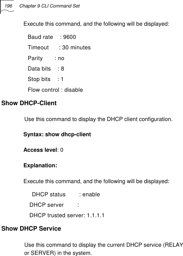
![Chapter 9 CLI Command Set 197 Syntax: show dhcp service Access level: 0 Show DHCP Binding Use this command to display address bindings on Dynamic Host Configuration Protocol (DHCP) server. Syntax: show dhcp binding [ip-address] | [manual ] | [ auto] Possible value: ip-address: Specifies the IP address of the DHCP client for which bindings will be displayed Manual: Displays only manual binding’s address Auto: Displays only auto binding’s address Default value: All address bindings are shown. Access level: 0 Show DHCP Relay Use this command to display DHCP relay agent’s configuration parameters. Syntax: show dhcp relay Access level:0](https://usermanual.wiki/UTStarcom-Telecom/3001P/User-Guide-506514-Page-226.png)
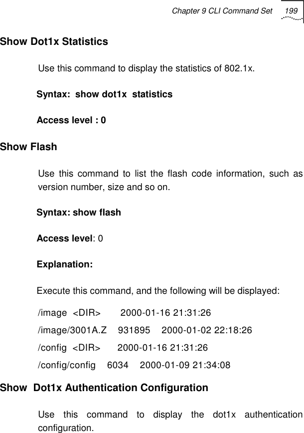
![198 Chapter 9 CLI Command Set Show DHCP Server Use this command to display DHCP server’s configuration parameters. Syntax: show dhcp server Access level:0 Show DHCP Statistics Use this command to display Dynamic Host Configuration Protocol (DHCP) Server statistics. Syntax: show dhcp statistics [relay |server] Default value: all statistics Access level: 0 Show Dot1x Configuration Use this command to display the PAE capabilities, protocol version, and other global dot1x parameters such as max-req, re-authperiod, server-timeout supplicant-timeout and so on. Syntax: show dot1x Access level: 0](https://usermanual.wiki/UTStarcom-Telecom/3001P/User-Guide-506514-Page-227.png)
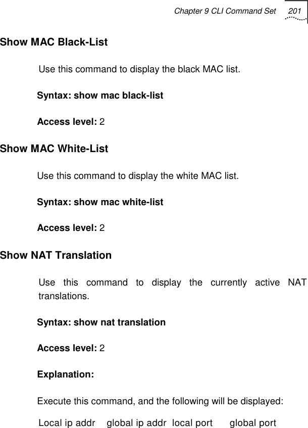
![200 Chapter 9 CLI Command Set Syntax: show dot1x authentication configuration Access level: 0 Show MAC Use this command to display the MAC addresses. Syntax: show mac [type] [port] Possible value: type: static | dynamic Access level: 0 Explanation: Execute this command, and the following will be displayed: MAC State Port Pass-time Ageing-Time ----------------------------------------------- 00:06:5b:2c:eb:f8 Dynamic LAN 215 300 00:06:5b:a2:07:f2 Dynamic LAN 264 300 00:08:74:9c:e7:f0 Dynamic LAN 228 300 00:08:74:92:07:ee Dynamic LAN 221 300 00:0b:db:53:77:eb Dynamic LAN 223 300 00:08:74:f1:8f:e5 Dynamic LAN 219 300](https://usermanual.wiki/UTStarcom-Telecom/3001P/User-Guide-506514-Page-229.png)

![Chapter 9 CLI Command Set 203 MAC address : IP address : Subnet mask : Default gateway : (wan only) Show IP-Route Use this command to display the static or all route entries. Syntax: show ip-route [static] Access level: 0 Show Access-List Configuration Use this command to display the access-list configuration. Syntax: show access-list configuration Access level: 0 Show Port Config Use this command to display the configuration information of one or all ports, such as speed duplex, priority, PVID and so on. Syntax: show port config Access level: 0](https://usermanual.wiki/UTStarcom-Telecom/3001P/User-Guide-506514-Page-232.png)
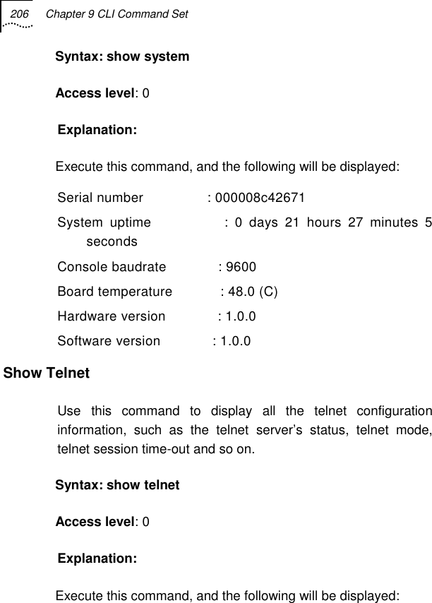
![Chapter 9 CLI Command Set 205 Syntax: show sms user {name <name> | mac <macaddr> | {all | dynamic | static}} [parameters]] Possible value: parameters : [lock<enable/disable>] Access level : 0 Show SMS Online-User Use this command to show the online user ‘s information. Syntax: show sms online-user Access level : 0 Show Wireless-Port Use this command to show the wireless port configuration information. Syntax: show wireless-port Access level: 0 Show System Use this command to display the system information, such as contact, location, name, up-time, software version, hardware version and so on.](https://usermanual.wiki/UTStarcom-Telecom/3001P/User-Guide-506514-Page-234.png)