UTStarcom Telecom 3001P Access Point User Manual
UTStarcom Telecom Co., Ltd. Access Point Users Manual
Users Manual

WA3001 Indoor AP
Wireless Access Point
USER GUIDE
Release: 1.1
Doc. Code: L3 DW09 1000 02 010 00
UTStarcom, Inc.
Copyright © 2004 UTStarcom, Inc. All rights reserved.
No part of this documentation may be reproduced in any form or by any means or
used to make any derivative work (such as translation, transformation, or
adaptation) without prior, express and written permission from UTStarcom, Inc.
UTStarcom, Inc. reserves the right to revise this documentation and to make
changes in content from time to time without obligation on the part of UTStarcom,
Inc. to provide notification of such revision or changes.
UTStarcom, Inc. provides this documentation without warranty of any kind, implied
or expressed, including but not limited to, the implied warranties of merchantability
and fitness for a particular purpose. UTStarcom may make improvements or
changes in the product(s) and/or the program(s) described in this documentation
at any time.
UNITED STATES GOVERNMENT LEGENDS:
If you are a United States government agency, then this documentation and the
software described herein are provided to you subject to the following:
United States Government Legend: All technical data and computer software is
commercial in nature and developed solely at private expense. Software is
delivered as Commercial Computer Software as defined in DFARS 252.227-7014
(June 1995) or as a commercial item as defined in FAR 2.101(a) and as such is
provided with only such rights as are provided in UTStarcom's standard
commercial license for the Software. Technical data is provided with limited rights
only as provided in DFAR 252.227-7015 (Nov 1995) or FAR 52.227-14 (June
1987), whichever is applicable. You agree not to remove or deface any portion of
any legend provided on any licensed program or documentation contained in, or
delivered to you in conjunction with, this User Guide.
UTStarcom, the UTStarcom logo, PAS, mSwitch, Airstar, WACOS, Netman, Total
Control, and CommWorks are registered trademarks of UTStarcom, Inc. and its
subsidiaries. The UTStarcom name, AN-2000, and the CommWorks logo are
trademarks of UTStarcom, Inc. and its subsidiaries.
Other brand and product names may be registered trademarks or trademarks of
their respective holders.
Any rights not expressly granted herein are firmly reserved.

Regulatory statement (FCC)
The users manual or instruction manual for an intentional or
unintentional radiator shall caution the user that changes or
modifications not expressly approved by the party responsible
for compliance could void the user's authority to operate the
equipment.
IMPORTANT NOTE (CO-LOCATION)
FCC RF Radiation Exposure Statement: This equipment
complies with FCC RF radiation exposure limits set forth for an
uncontrolled environment. This device and its antenna must not
be co-located or operating in conjunction with any other
antenna or transmitter.
MPE Statement (Safety Information)
Your device contains a low power transmitter. When device is
transmitted it sends out Radio Frequency (RF) signal.
Safety Information
In order to maintain compliance with the FCC RF exposure
guidelines, this equipment should be installed and operated with
minimum distance 20cm between the radiator and your body.
Use only with supplied antenna. Unauthorized antenna,
modification, or attachments could damage the transmitter and
may violate FCC regulations.

15.105(b) Information of the responsible party for a DoC product
The identification of the product:
Product Name: Wireless Access Point
Model: WA3001
Technical Support:
UTStarcom Telecom Co., Ltd.
Address:
NO.88 Wenhua Road,
Hangzhou PRC 310012
Telephone : 0571-88862342-3524
Email: cbshi@utstar.com
Technical Support in the US:
UTStarcom, Inc.
Address:
1275 Harbor Bay Parkway
Alameda, CA 94502 USA
Telephone: 1 (866) 663-3266
Email: ips@utstar.com
15.21 Regulatory information / Disclaimers
The users manual or instruction manual for an intentional or unintentional radiator shall caution
the user that changes or modifications not expressly approved by the party responsible for
compliance could void the user's authority to operate the equipment.
15.105 Federal Communications Commission (FCC) Requirements, Part 15
This equipment has been tested and found to comply with the limits for a class B digital device,
pursuant to part 15 of the FCC Rules. These limits are designed to provide reasonable
protection against harmful interference in a residential installation.
This equipment generates, uses and can radiate radio frequency energy and, if not installed
and used in accordance with the instructions, may cause harmful interference to radio
communications. However, there is no guarantee that interference will not occur in a particular
installation. If this equipment does cause harmful interference to radio or television reception,
which can be determined by turning the equipment off and on, the user is encouraged to try to
correct the interference by one or more of the following measures:
---Reorient or relocate the receiving antenna.
---Increase the separation between the equipment and receiver.
---Connect the equipment into an outlet on a circuit different from that to which the receiver is
connected.
---Consult the dealer or an experienced radio/TV technician for help.

Regulatory statement (CE R&TTE)
European standards dictate maximum radiated transmit power
of 100mW EIRP and frequency range 2.400-2.4835GHz; In
France, the equipment must be restricted to the 2.4465-
2.4835GHz frequency range and must be restricted to indoor
use.
Declaration of Conformity
For the following equipment: WA3001 Access Point
!
0984
Is herewith confirmed to comply with the requirements set out in
the Council Directive on the Approximation of the Laws of the
Member States relating to Electromagnetic Compatibility
(89/336/EEC), Low-voltage Directive (73/23/EEC) and the
Amendment Directive (93/68/EEC), the procedures given in
European Council Directive 99/5/EC and 89/3360EEC.
The equipment was passed. The test was performed according
to the following European standards:
• EN 300 328 V.1.4.1 (2003-04)
• EN 301 489-1 V.1.3.1 (2001-09) / EN 301 489-17 V.1.1.1
(2000-09)
• EN 50371: 2002
• EN 60950: 2000

Contents
1 Product Introduction ..................................................................... 1
Product Introduction..................................................................................... 2
Product Features ......................................................................................... 3
2 System Application........................................................................ 5
Wireless Network Access (MiniPCI Network Card)....................................... 5
Single-cell Wireless Network.................................................................... 5
Multiple APs in Separate Networks .......................................................... 6
Multiple APs within a Network .................................................................. 7
Extension of Wired Network..................................................................... 7
Repeater Mode (CardBus Adapter).............................................................. 8
Point-to-Point Mode ................................................................................. 8
Point-to-Multiple Points Mode................................................................... 9
Repeater + AP Combined Network ............................................................ 10
3 Hardware Installation................................................................... 11
Package Contents ..................................................................................... 11
Installation Requirements........................................................................... 11
Product Physical Characteristics................................................................ 12
Product Front View................................................................................. 12
Product Side View.................................................................................. 13
Product Top View................................................................................... 15

ii
Hardware Installation..................................................................................15
System Access...........................................................................................16
Firmware Description..................................................................................18
4 Web-based Configuration Introduction......................................21
Configuration Flow......................................................................................21
System Configuration Introduction..............................................................21
Bridge/Router Mode Introduction ................................................................23
Logon the System.......................................................................................28
Save and Reboot........................................................................................30
5 Web-based Configuration............................................................33
Guide Configuration....................................................................................36
Wireless Port Configuration ........................................................................39
DHCP Server Configuration........................................................................45
WAN Interface Configuration ......................................................................48
LAN Interface Configuration........................................................................52
Radius Client..............................................................................................53
802.1x Authentication .................................................................................55
User Management......................................................................................61
Dynamic Users .......................................................................................61
Static Users ............................................................................................63
ARP Management ......................................................................................65
Route Configuration....................................................................................66

iii
NAT Configuration ..................................................................................... 67
NAPT Mode ........................................................................................... 68
Basic NAT Mode .................................................................................... 70
Isolation&filter Configuration ...................................................................... 71
MAC Management..................................................................................... 73
6 Web-based System Configuration.............................................. 77
Viewing System Information....................................................................... 77
Changing Password................................................................................... 78
Managing File System ............................................................................... 79
Debug Configuration.................................................................................. 82
7 Performance Statistics................................................................ 85
Interface Statistics ..................................................................................... 85
DHCP Server Statistics.............................................................................. 87
DHCP Relay Statistics ............................................................................... 91
RADIUS Client Statistics............................................................................ 93
ARP Table ................................................................................................. 95
Route Table............................................................................................... 96
Online User Information............................................................................. 97
MAC Address............................................................................................. 99
8 Web-based Configuration Examples........................................ 101
AP in Bridge Mode................................................................................... 101

iv
AP in Router Mode (Case 1).....................................................................106
AP in Router Mode (Case 2).....................................................................111
9 CLI Command Set ......................................................................117
EXEC Commands ....................................................................................117
Debug...................................................................................................117
Enable ..................................................................................................117
Clear.....................................................................................................118
End.......................................................................................................118
Exit .......................................................................................................118
History ..................................................................................................119
Logout ..................................................................................................119
Ping ......................................................................................................119
Quit.......................................................................................................120
Show ....................................................................................................120
Tree......................................................................................................120
Write Memory .......................................................................................120
Privileged EXEC Commands....................................................................121
Configure..............................................................................................121
Copy Config to TFTP ............................................................................121
Copy Config from TFTP ........................................................................122
Copy Image From TFTP .......................................................................122
Copy Image to TFTP.............................................................................123

v
Disable................................................................................................. 123
Erase Config........................................................................................ 123
Clear ARP............................................................................................ 124
Clear DHCP Binding ............................................................................ 124
Clear DHCP Statistics.......................................................................... 125
Clear Dot1x Statistics........................................................................... 125
Clear RADIUS...................................................................................... 125
Clear MAC ........................................................................................... 126
Clear NAT............................................................................................ 126
Clear NAT Translation.......................................................................... 126
Kill........................................................................................................ 126
Reboot ................................................................................................. 127
Auto-config Enable/Disable.................................................................. 127
Global Config Commands........................................................................ 127
AP-Mode.............................................................................................. 127
ARP Entry............................................................................................ 128
Broadcast Limit .................................................................................... 128
Console Baud-Rate.............................................................................. 129
Console Timeout.................................................................................. 129
DHCP Service...................................................................................... 130
DHCP-Client Enable /Disable............................................................... 130
DHCP-Client Trust ............................................................................... 131

vi
DHCP-Pool...........................................................................................131
DHCP-Server Host................................................................................131
Dot1x Authentication Enable / Disable ..................................................132
Dot1x Authentication Mode...................................................................132
Dot1x Encryption-Mode.........................................................................133
Dot1x Initialize ......................................................................................133
Dot1x Max-Req.....................................................................................134
Dot1x Quiet-Period ...............................................................................134
Dot1x Re-Authenticate..........................................................................135
Dot1x Re-Authentication .......................................................................136
Dot1x Re-Authperiod ............................................................................137
Dot1x Server-Timeout...........................................................................137
Dot1x Supplicant-Timeout.....................................................................138
Dot1x TX-Period ...................................................................................139
Dynamic-User.......................................................................................140
Dynamic-User Enable / Disable ............................................................140
Ethernet-Port ........................................................................................141
Hostname .............................................................................................141
IAPP .....................................................................................................141
Interface................................................................................................142
IP Default-Route ...................................................................................142
IP RADIUS Source-Interface.................................................................143
IP Route................................................................................................143

vii
Isolation ............................................................................................... 144
Load-Balance Enable/Disable .............................................................. 144
Load-Balance Mode............................................................................. 145
MAC Age Time..................................................................................... 145
MAC Black-List .................................................................................... 145
Max-Online-User.................................................................................. 146
NAT Enable/Disable............................................................................. 146
NAT Interface....................................................................................... 147
NAT Map.............................................................................................. 147
NAT Mode............................................................................................ 148
NAT Pool ............................................................................................. 148
NAT Redirect ....................................................................................... 148
NAT Timeout........................................................................................ 149
Operator Access level.......................................................................... 149
Operator Add / Delete .......................................................................... 150
Operator Password .............................................................................. 151
PPPoE Auto-Connect Disable/Enable .................................................. 152
PPPoE Connect................................................................................... 152
PPPoE Disconnect............................................................................... 152
PPPoE User......................................................................................... 152
RADIUS-Acctserver {Enable | Disable}................................................ 153
RADIUS-Acctserver Host..................................................................... 153

viii
RADIUS-Acctserver Info .......................................................................154
RADIUS-Authserver {Enable | Disable}.................................................155
RADIUS-Authserver Extra.....................................................................155
RADIUS-Authserver Host......................................................................155
RADIUS-Authserver Info.......................................................................156
RADIUS-Server Dead-Time..................................................................157
RADIUS-Server Retransmit...................................................................157
RADIUS-Server Timeout.......................................................................158
SNMP Client.........................................................................................158
SNMP Server Community.....................................................................159
SNMP Server Contact...........................................................................159
SNMP Server Enable/Disable ...............................................................159
SNMP Server Location..........................................................................160
SNMP Server Sysname........................................................................160
SNMP Server Trap Enable/Disable.......................................................160
SNMP Server Trap Host .......................................................................161
Static-MAC-Address .............................................................................161
Static-User............................................................................................162
Static-User Enable / Disable .................................................................162
Telnet Client..........................................................................................162
Telnet Server Enable / Disable..............................................................163
Telnet Timeout......................................................................................163
User-Force-Offline ................................................................................164

ix
VLAN Default VID ................................................................................ 164
VLAN Employee Default VID................................................................ 164
VLAN Enable/Disable........................................................................... 165
VLAN Mode.......................................................................................... 165
VLAN port-vid....................................................................................... 166
VLAN Tag Disable................................................................................ 166
VLAN Tag Enable ................................................................................ 167
VLAN Visitor Default Vid ...................................................................... 167
Webserver ........................................................................................... 167
Wireless-Port ....................................................................................... 168
DHCP-pool Configuration Mode............................................................... 168
DNS-Server.......................................................................................... 168
Excluded-Address................................................................................ 169
Gateway............................................................................................... 170
Lease................................................................................................... 171
Network................................................................................................ 172
Manual-Binding.................................................................................... 172
Ethernet Port configuration level .............................................................. 173
Speed-duplex....................................................................................... 173
Interface Mode Commands...................................................................... 173
Disable................................................................................................. 173
Enable ................................................................................................. 174

x
IP Address............................................................................................174
Wireless Port Configuration Level.............................................................174
Beacon Interval.....................................................................................174
Basic Rate ............................................................................................175
Fragment Threshold..............................................................................176
Frequency-Channel ..............................................................................176
DTIM Interval ........................................................................................177
Power ...................................................................................................177
RTS-CTS Threshold .............................................................................178
SSID.....................................................................................................178
Tx Rate.................................................................................................179
Wireless Mode......................................................................................179
WDS-Mode Enable / Disable.................................................................180
WDS Peer MAC....................................................................................180
WEP Encryption Enable / Disable .........................................................181
WEP Encryption Key.............................................................................181
Default WEP-Key..................................................................................182
WEP-Key-Format..................................................................................182
WEP-Key-Length..................................................................................182
Antenna ................................................................................................183
WPA Mode ...........................................................................................183
WPA Encryp-Mode ...............................................................................184
WPA Psk-Passphrase...........................................................................184

xi
WPA Groupkey-Update-Interval........................................................... 184
Optimize-108g Enable/Disable............................................................. 185
Webserver Mode ..................................................................................... 185
Enable/Disable..................................................................................... 185
IP-Filter Enable/Disable........................................................................ 186
IP-Filter Client ...................................................................................... 186
Port-Filter............................................................................................. 186
IAPP Mode .............................................................................................. 187
Enable/Disable..................................................................................... 187
ESP Enable/Disable............................................................................. 187
Mode.................................................................................................... 187
Map...................................................................................................... 188
Secret .................................................................................................. 188
Debug Mode............................................................................................ 189
Ping ..................................................................................................... 189
Debug-Module ..................................................................................... 189
NAT Logging........................................................................................ 190
NAT Print ............................................................................................. 190
Sys-Function........................................................................................ 191
Show Version....................................................................................... 191
Show Memory...................................................................................... 192
Show NAT Run .................................................................................... 192

xii
Show Debug_Module............................................................................192
Net-Security Rate-Limit Enable/Disable ................................................193
Net-Security Syn-Cache Enable/Disable...............................................193
Net-Security Attack-Defense Enable/Disable ........................................193
Show Net-Security................................................................................193
Ipstack Debug.......................................................................................194
Show Ipstack-Debug.............................................................................194
Show ........................................................................................................195
Show ARP ............................................................................................195
Show Console.......................................................................................195
Show DHCP-Client ...............................................................................196
Show DHCP Service.............................................................................196
Show DHCP Binding.............................................................................197
Show DHCP Relay................................................................................197
Show DHCP Server..............................................................................198
Show DHCP Statistics...........................................................................198
Show Dot1x Configuration ....................................................................198
Show Dot1x Statistics ...........................................................................199
Show Flash...........................................................................................199
Show Dot1x Authentication Configuration ............................................199
Show MAC............................................................................................200
Show MAC Black-List ...........................................................................201
Show MAC White-List...........................................................................201

xiii
Show NAT Translation ......................................................................... 201
Show NAT Configuration...................................................................... 202
Show Managed-Interface ..................................................................... 202
Show IP-Route..................................................................................... 203
Show Access-List Configuration........................................................... 203
Show Port Config................................................................................. 203
Show RADIUS Configuration................................................................ 204
Show RADIUS Statistics ...................................................................... 204
Show Sms User ................................................................................... 204
Show SMS Online-User ....................................................................... 205
Show Wireless-Port.............................................................................. 205
Show System....................................................................................... 205
Show Telnet......................................................................................... 206
Show SNMP Server Configuration ....................................................... 207
Show AP-Mode.................................................................................... 207
Show Load-Balance Configuration ....................................................... 207
Show Who ........................................................................................... 208
Show Running-Config .......................................................................... 208
Show Startup ....................................................................................... 208
Show WPA Configuration..................................................................... 208
Show Webserver.................................................................................. 209
Show VLAN Configuration.................................................................... 209

xiv
Show VLAN Binding..............................................................................210
Show IAPP Configuration......................................................................211
10 Troubleshooting.........................................................................213
11 Technical Specifications............................................................215
12 Acronyms and Abbreviations....................................................219

xv
List of Figures
Figure 1 Single-cell Wireless Network Topology .................................................. 6
Figure 2 Multi-APs with different ESS_IDs in Separate Networks Topology ......... 6
Figure 3 Multi-APs within a Network Topology..................................................... 7
Figure 4 Extension of Wired Network Topology.................................................... 8
Figure 5 Repeater Point-to-Point Mode Network Topology................................... 9
Figure 6 Repeater Point to Multi-points Mode Network Topology......................... 9
Figure 7 Repeater+AP Combined Network Topology......................................... 10
Figure 8 WA3001 Front View............................................................................. 12
Figure 9 WA3001 Side View (1)......................................................................... 13
Figure 10 WA3001 Side View (2)....................................................................... 14
Figure 11 WA3001 Top View ............................................................................. 15
Figure 12 Installation Diagram ........................................................................... 16
Figure 13 Logon Window................................................................................... 18
Figure 14 Configuration Flow Chart ................................................................... 21
Figure 15 Logon Successful............................................................................... 28
Figure 16 AP Reboot Prompt Window................................................................ 30
Figure 17 Save and Reboot ............................................................................... 30
Figure 18 Basic Configuration............................................................................ 34
Figure 19 Advanced Configuration Part I ........................................................... 35

xvi
Figure 20 Advanced Configuration Part II ...........................................................36
Figure 21 Basic Config - Wireless Port Config ....................................................40
Figure 22 Wireless Port Configuration ................................................................43
Figure 23 DHCP Server Configuration................................................................46
Figure 24 WAN Port Configuration Interface.......................................................49
Figure 25 Trusted DHCP Server Configuration...................................................51
Figure 26 LAN Interface Configuration................................................................52
Figure 27 Radius Client Configuration Interface..................................................54
Figure 28 802.1x Authentication Configuration ...................................................57
Figure 29 Dynamic User Configuration Interface.................................................62
Figure 30 Static User Configuration Interface .....................................................64
Figure 31 ARP Configuration Interface ...............................................................65
Figure 32 Route Configuration Interface .............................................................66
Figure 33 Table 5-1 Route Configuration Interface Spec ....................................67
Figure 34 NAT Configuration Interface................................................................67
Figure 35 Table 5-2 NAT Configuration Specification..........................................68
Figure 36 NAT Static MAP Configuration Interface .............................................70
Figure 37 Isolation&filter Configuration Interface.................................................72
Figure 38 MAC Table Configuration Interface.....................................................74
Figure 39 System Information.............................................................................77
Figure 40 Change Password ..............................................................................78
Figure 41 File System.........................................................................................80
Figure 42 Confirm Configuration File Erase ........................................................82

xvii
Figure 43 Initiating Configuration File Erase Message ....................................... 82
Figure 44 Debug Configuration.......................................................................... 83
Figure 45 Interface Statistics.............................................................................. 86
Figure 46 DHCP Server Statistics...................................................................... 88
Figure 47 DHCP Relay Statistics ....................................................................... 92
Figure 48 RADIUS Client Statistics.................................................................... 94
Figure 49 ARP Table ......................................................................................... 96
Figure 50 Route Table....................................................................................... 97
Figure 51 Online User Information ..................................................................... 98
Figure 52 MAC Address..................................................................................... 99
Figure 53 Network Topology............................................................................ 101

xviii
List of Tables
Table 1 WA3001 Front Panel LED Indicators......................................................13
Table 2 Wireless Frequency Channel Default Setting..........................................19
Table 3 Configuration Menu in Bridge Mode .......................................................23
Table 4 Configuration Menu in Router Mode.......................................................24
Table 5 Wireless Port 1 Interface Specification ...................................................40
Table 6 WA3001 WEP Encryption Configuration.................................................42
Table 7 Wireless Port 2 Interface Specification ...................................................43
Table 8 DHCP Server Configuration Specification...............................................47
Table 9 WAN Interface Configuration Specification.............................................50
Table 10 LAN Interface Specification ..................................................................53
Table 11 Radius Client Configuration Specification.............................................54
Table 12 802.1x Configuration Specification .......................................................58
Figure 33 Table 5-1 Route Configuration Interface Spec ....................................67
Figure 35 Table 5-2 NAT Configuration Specification..........................................68
Table 13 MAC Filter Configuration Specification .................................................72
Table 14 File System Window Description ..........................................................81
Table 15 Interface Statistics Window Description................................................86
Table 16 DHCP Server Statistics Window Description ........................................88
Table 17 DHCP Relay Statistics Window Description..........................................92

xix
Table 18 RADIUS Client Statistics Window Description...................................... 94
Table 19 Online User Information Window Description....................................... 98
Table 20 Troubleshooting................................................................................. 213
Table 21 WA3001 AP Technical Specifications................................................ 215

1 Product Introduction
WA3001 is a switch-like WLAN Access Point that offers
industry-leading performance/price ratio and a comprehensive
feature set. It is designed especially for a Wireless Internet
Service Provider (WISP) that provides Wireless Internet
services - including hotspot and corporate deployment planning.
WA3001 supports IEEE802.11b and 802.11g, SNMP
centralized network management, authentication and billing
systems. It provides a variety of security mechanisms to ensure
safer data transmission within the public network.
WA3001 is the premier choice for WISP Hotspot Network
Solutions because of its user-friendly design, high-speed data
transmission rate of up to 54Mbps, additional long distance
network coverage and high sensitivity. WA3001 is typically
applied in public areas such as airports, hotels, exhibitions, bars
and news centers.
WA3001 also supports NT authentication to provide a cost-
effective and efficient wireless connection for corporations.
Using its 4 LAN ports switch like functionality ensures
customers always enjoy an easy network buildup.
Presently, the new WLAN technology is focused on throughput
rates and network coverage improvement, along with the
1

2 Chapter 1 Product Introduction
elimination of blind spots. UTStarcom has made rapid progress
on all of these areas utilizing the latest XR and Super G
technology.
Product Introduction
Port Introduction:
- One 10/100M Ethernet WAN port
- Four 10/100M Ethernet LAN ports
- One Mini-PCI socket supports Type III PC card
- One hot pluggable CardBus socket supports Type II PC
card
- One RS-232 port for management and console
Compliance:
- IEEE 802.3X, duplex 10BaseT, 100BaseTX ports
- IEEE802.3u, 100BaseTX specification
- IEEE802.3, 10BaseT specification
- IEEE802.3af standard
- CardBus socket supports both 16-bit PC Cards and 32-bit
CardBus Cards
- CardBus is compliant with the PCI Local Bus Specification
Revision 2.2
- Mini-PCI socket supports the PCI Local Bus Specification
Revision 2.2

Chapter 1 Product Introduction 3
Connector:
- 10/100Base-TX port: RJ-45
- Management console ports: RS-232
Product Features
• 6M/s throughput rate
• Supports 802.3af inline power supply (PoE)
• Compatible with 802.11b and 802.11g
• Supports four adjustable RF power levels (10mw–20mw–
50mw-100mw)
• Supports 64/128-bit WEP Encryption
• Supports 802.1x to provide high data security
• Supports EAP-MD5
• Supports DHCP server
• Supports WEB pass-through
• Supports PPPoE
• Provides remote management and diagnosis (Inband and
Outband)
• Supports Layer2 ACL (at least 256 in the access control
list)
• Supports broadcast threshold
• Supports end-user isolated and VLAN

4 Chapter 1 Product Introduction
• Supports user-access load-share (roundrobin&
leastconn&hash) and control based on flow and user
number
• Supports NAT or any IP
• Supports link-test (default-gateway is unavailable for
WA3001)
• Supports Repeater mode (dual mode)
• Super G maximize network throughput, peak flow is able to
reach the wire LAN throughput at 10/100M. It exceeds the
previous generation wireless functionality
• Supports XR, the received sensibility reach -103dBm
• Operation temperature: -15 ~ 50°C
• Network Management
- WEB based configuration
- Supports SNMP MIB (MIB II or private MIB)
- SNMP Agent
- Console port management
- In-Band/Out-Band network management
- Statistic

2 System Application
WA3001 is built with both regular AP (miniPCI network card)
and Repeater (CardBus adapters) functions. As a Repeater,
from network coverage point of view, the AP can be configured
in point-to-point (P2P) mode or point-to-multiple points (P2MP)
mode (one AP connects with up to four APs). As a regular
adapter, the AP can be configured as a single-cell network, a
multi-cell network, or an extension of wired network.
Wireless Network Access (MiniPCI Network Card)
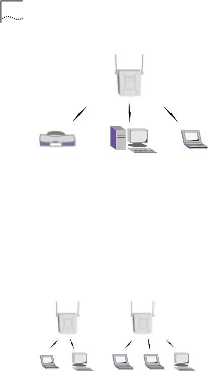
Single-cell Wireless Network
A single AP used without the wired network providing a single-
cell wireless network for peer-to-peer stations.
E.g. In SOHO mode, the AP provides a quick and efficient
solutions to printers, PCs and Server.
2
6 Chapter 2 System Application
Figure 1 Single-cell Wireless Network Topology
Multiple APs in Separate Networks
Multiple APs can coexist as separate networks in the same site
without interference by using different ESS_IDs.
E.g. In an exhibition, where each company’s network is
independent
Figure 2 Multi-APs with different ESS_IDs in Separate
Networks Topology
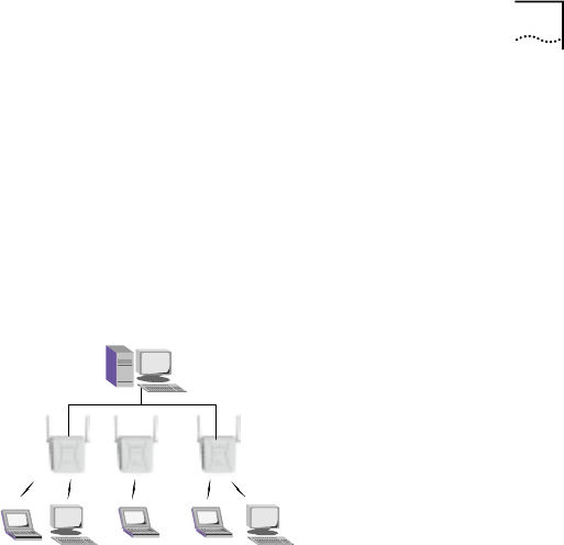
Chapter 2 System Application 7
Multiple APs within a Network
Multiple APs wired together provide a network with a better
coverage area and performance - by using the same ESS_ID.
E.g. Within a company, each department accesses a public file
server through its own AP.
Figure 3 Multi-APs within a Network Topology
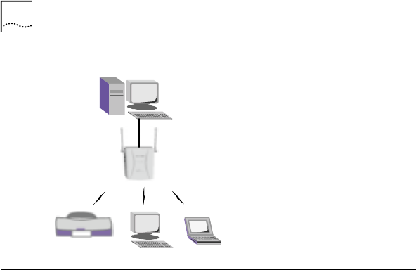
Extension of Wired Network
AP can connect to the wired network through WAN ports, or
connect to wireless clients through wireless ports.
E.g.: In a company, using APs to quickly setup a network for a
newly added department is an efficient way to extend the
existing wired network.
8 Chapter 2 System Application
Figure 4 Extension of Wired Network Topology
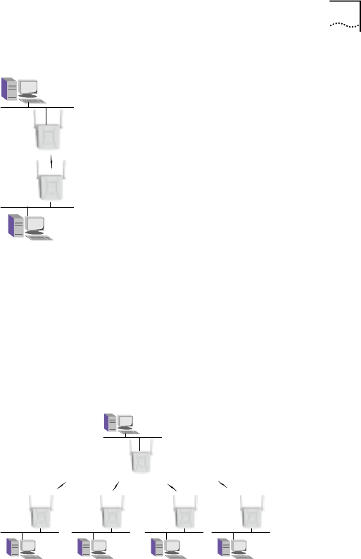
Repeater Mode (CardBus Adapter)
Point-to-Point Mode
Point-to-Point mode is used to connect two networks in WLAN
application.
E.g.: In a campus, using WA3001’s point-to-point mode to
connect two buildings in a separate wired network. In this mode,
AP must to be configured with a cardBus adapter to function as
a repeater.
Chapter 2 System Application 9
Figure 5 Repeater Point-to-Point Mode Network Topology
Point-to-Multiple Points Mode
In WLAN application, point-to-multiple points mode dramatically
expands network coverage and quickly establishes the
connectivity among existing networks.
Figure 6 Repeater Point to Multi-points Mode Network
Topology
10 Chapter 2 System Application
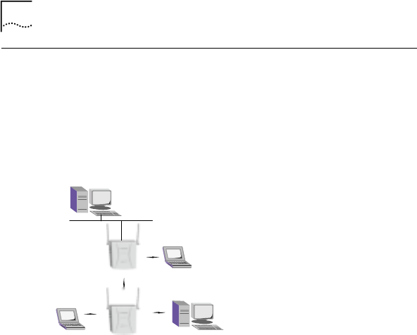
Repeater + AP Combined Network
Capable of being a wireless entrance for wireless clients, or a
repeater of a wired network, the WA3001 expands network
coverage easily via wireless connection.
Figure 7 Repeater+AP Combined Network Topology

3 Hardware Installation
Package Contents
Before using this AP, check the accessories in the box. If you
find anything missing or the documentation set is incomplete,
contact your local dealer immediately. The following
accessories are shipped with the product:
• One WA3001 AP
• One user guide
• One power adapter
• Two small antennas
• One installation bracket
• Three screws
• One warranty card
Installation Requirements
AP installation environment:
• WA3001 power supply mode:
- Support IEEE802.3af, remote Cat 5, DC -48V/300mA
3
12 Chapter 3 Hardware Installation
- Support local DC 12V/1.25A
Note: The two power supply modes cannot be used
simultaneously. In PoE power supply mode, RJ45 4/5(+)7/8(-)
connects to WAN port.
• One RJ-45 LAN port, supports 10/100Mbps data
transmission rate
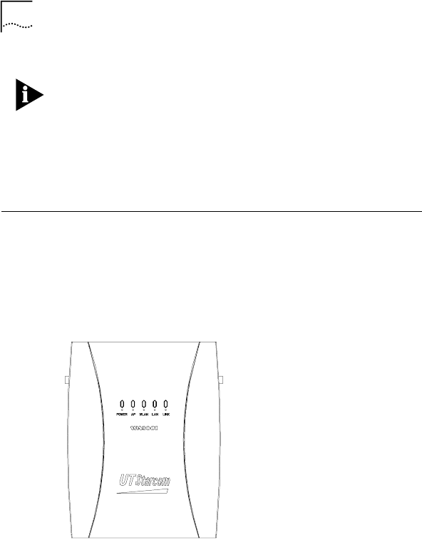
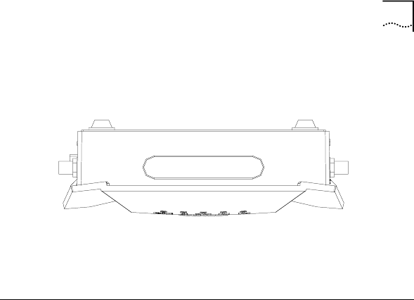
Product Physical Characteristics
Product Front View
Figure 8 WA3001 Front View
Chapter 3 Hardware Installation 13
Table 1 shows the list of LED indicators (from left to right) on
the front panel along with their activity status and descriptions
Table 1 WA3001 Front Panel LED Indicators
LED
Indicators Status Description
POWER Lighting in
green Lights when power is being supplied
well
AP Lighting in
green Lights when AP is able to be
connected by clients
Off: No wireless channel
WLAN Blinking in
green Blinking: with wireless connections
Off: No Ethernet connection
LAN Blinking in
green Blinking: with LAN connection
Off: No accessing activities from
wireless clients.
LINK Lighting in
green Lighting: AP gets connected by
wireless clients
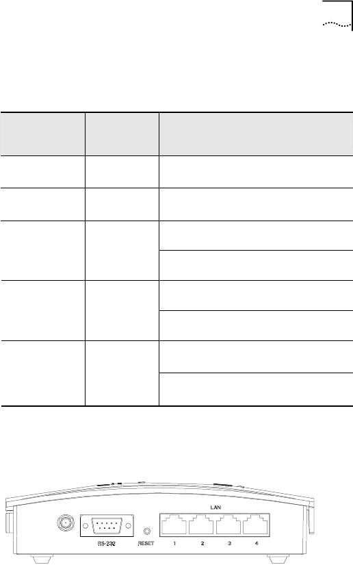
Product Side View
Figure 9 WA3001 Side View (1)
14 Chapter 3 Hardware Installation
The following table lists the items on side panel (1) (from left to
right)
Interface Description
Console port RS-232 connector for LAN
management
RESET Restore button to reboot/reset the
AP to its default settings
LAN Four LAN ports to access Ethernet,
RJ-45 connector
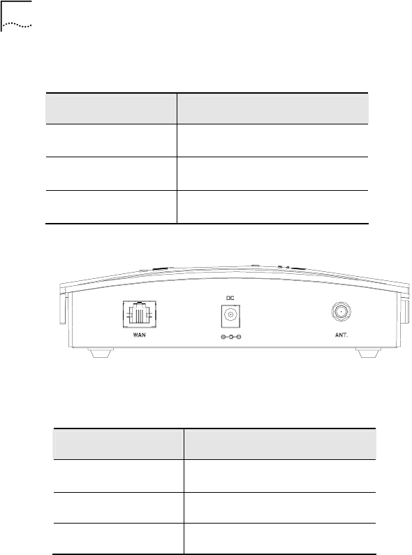
Figure 10 WA3001 Side View (2)
The following table lists the items on the side panel (2) (from left
to right)
Interface Description
WAN WAN port used for uplink
connection. RJ-45 connector
DC Power jack, 12V
ANT Antenna installation jack
Chapter 3 Hardware Installation 15
Product Top View
Figure 11 WA3001 Top View
WA3001 AP’s rubber top shown in Figure 11 is for installing a
Wireless LAN CardBus Adapter.
Hardware Installation
Steps:
1. Location: Place the AP in an appropriate place in a
room.
2. Antenna: Screw two antennae into both side of the AP
3. Install bracket (or put the AP on the table directly)
4. Fix the AP into the bracket

16 Chapter 3 Hardware Installation
Figure 12 Installation Diagram
System Access
Network management methods:
- Through LAN port: connects PC to LAN port that can
identify the connection automatically, use crossover or
straight-through network cable
- Through WAN port: connects PC to WAN port, use
crossover network cable
- Through wireless port: installs a wireless network card into
PC and find AP through Windows IE. The default ESSID is
“UT”
Note: It is suggested to use WAN or LAN port to configure the
AP.

Chapter 3 Hardware Installation 17
System default IP address:
- WAN port: 192.168.1.1/255.255.255.0
- LAN port: 172.18.37.1/255.255.255.0
Default user name and password:
- Administrator:
User name: admin
Password: admin
- Guest:
User name: guest
Password: guest
System access procedure:
1 Connects the power adapter to an AP
2 Makes sure that the connection between PC and AP’s LAN
port is connected.
3 Configures PC network card’s IP address to
172.18.37.100/255.255.255.0 in order to connect the PC to
LAN port
4 Enters AP LAN port’s default IP address into the PC web
browser at http://172.18.37.1
18 Chapter 3 Hardware Installation
5 Use the default user name and password to logon
User name: admin
Password: admin
Figure 13 Logon Window
Firmware Description
The default setting of WA3001 firmware is different according to
the nation-wide regulation of wireless frequency channel. The
AP configuration of this manual applies to China area only. The
values listed in Table 2 are wireless frequency channel default
settings of other areas.

Chapter 3 Hardware Installation 19
Table 2 Wireless Frequency Channel Default Setting
North
America/FCC
Europe/ETSI
Operation
Channel
2.412-2.462GHz 2.412-2.472GHz
Frequency
Channel
1-11 (Default: 1) 1-13 (Default: 1)
Mode b: 40mw (16dBm) Default RF
Power
Mode g: 25mw (14.5dBm) / 70mw (18.5dBm)
4 Web-based Configuration
Introduction
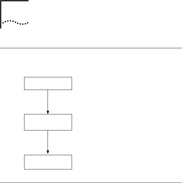
Configuration Flow
Figure 14 Configuration Flow Chart
Logon
Configuration
Save & Reboot
& Apply
System Configuration Introduction
Log on the system, select an operation mode and configure the
ports accordingly.
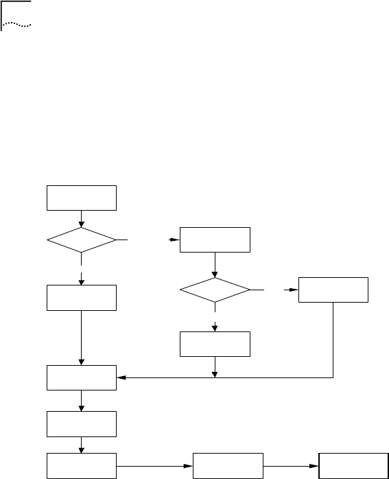
In Router mode, WAN port configuration depends on the retrieval
of IP address (Either DHCP server or DHCP client is provided). In
Bridge mode, configuration is not required for the WAN port.
4
22 Chapter 4 Web-based Configuration Introduction
The LAN port must be configured in both modes based on the IP
address.
In wireless mode, configure the wireless port and its channel
attributes.
After configuration, save it and reboot the system
Start
A P mode?
Bridge
Router
DHCP for
WAN?
Config IP
address
Get IP form
DHCP
Config LA N IP
address
W ireless Mode
config
SSID,
C h a n n e l c o n f ig
Yes
No
Two
interface
One i n t er f ac e
Save config Reboot
Chapter 4 Web-based Configuration Introduction 23
Bridge/Router Mode Introduction
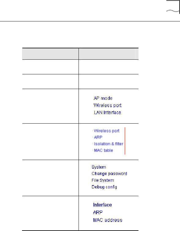
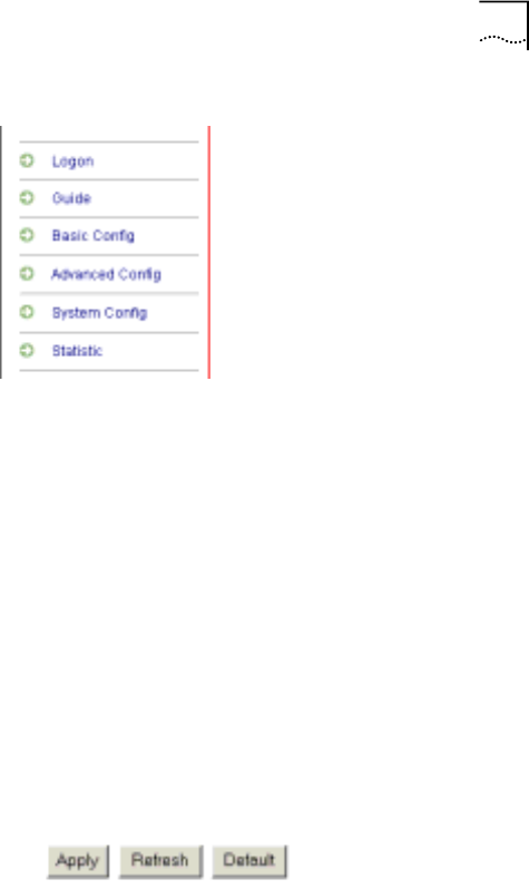
Table 3 Configuration Menu in Bridge Mode
Main Menu Sub Menu
Logon
Guide
Basic Config
Advanced Config
System Config
Statistic
24 Chapter 4 Web-based Configuration Introduction
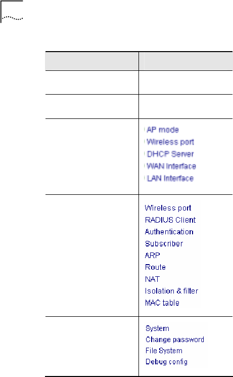
Table 4 Configuration Menu in Router Mode
Main Menu Sub Menu
Logon /
Guide /
Basic Config
Advanced Config
System Config
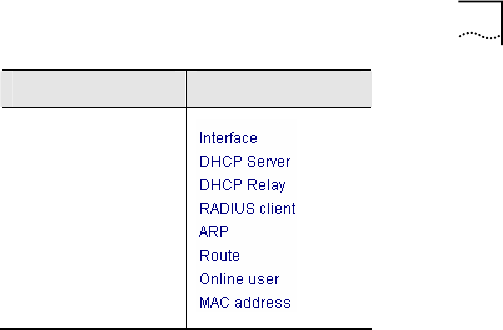
Chapter 4 Web-based Configuration Introduction 25
Main Menu Sub Menu
Statistic
Description:
• Wireless port configuration
- The system is able to configure two wireless network cards
at the same time. The default assumes a Mini PC card on
Wireless port 2.
- Configure the 802.11b attributes for the wireless port
- Activate WDS mode to implement Repeater functions
- Activate WEP encryption to provide data transmission
security. Four sets of Key values can be configured
• Interface configuration
- Include WAN and LAN ports
- Configure the port IP address to enable communication at
IP layer

26 Chapter 4 Web-based Configuration Introduction
• DHCP Server configuration
- Configure the DHCP server when the AP needs to allocate
an IP address to its clients
- Configure the DHCP address field attributes, or keep the
default attributes
- DHCP Client configuration
- Configure the DHCP client when the AP needs to allocate
an IP address to a client through the remote DHCP server
• Authentication
- Activate the option for 802.1x authentication
- Configure global user authentication attributes among the
Server, the AP and the Client.
• RADIUS Client configuration
- Configure this option while using a Radius server to
perform authentication or accounting
• Users Management: Dynamic, Static and Online users
- Configure this option while managing the users in local
authentication mode, local + Radius or Radius + local
mode
• NAT configuration
- In Router mode, configure the NAT when the system
requires AP to manage the IP addresses for its clients
- There are two types of NAT configurations: Static NAT and
NAPT (based on port forwarding)

Chapter 4 Web-based Configuration Introduction 27
• Route configuration
- In Router mode, users can define AP’s next route
• ARP management
- Provides information about network equipment connected
to the AP intended for users
• MAC filter configuration
- Manages the accessed users based on MAC. This includes
the MAC white list and black list
- Implements VLAN end-user isolation
• MAC table management
- Adds the MAC address table to speed forwarding of user
data
• System document management
- Manages the system documents remotely through FTP or
TFTP server. This includes Image and Config files
- Retrieves the default system’s configuration by deleting the
recently added configuration file
• Change user password
- Provides the option for users to increase the system’s
security
• Debug configuration
- Observes the system’s operational situation and makes it
convenient for advanced users to adjust and solve the
problems
28 Chapter 4 Web-based Configuration Introduction
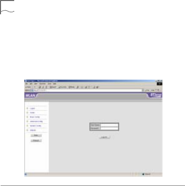
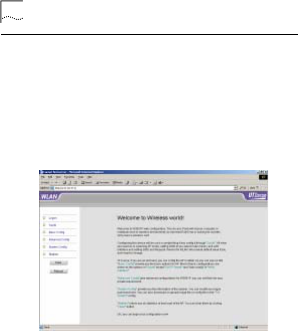
Logon the System
Access Methods:
Enter the default IP address in the browser’s logon field, then
enter the default user name and password.
Interface:
Figure 15 Logon Successful
Description:
• General introduction
The left panel is the function link area. The right panel is the
information display area and configuration area
Chapter 4 Web-based Configuration Introduction 29
• Left panel introduction
- Logon: log on the system
- Guide: A brief instructional guide describes the basic
system configuration of WA3001 step by step. It helps user
to complete the configuration quickly
- Basic Config: Implements the system’s basic configurations
- Advanced Config: Implements the system’s advanced
configurations
- System Config: Downloads/uploads the system files and
upgrades the image files
- Statisic: Statistical information about ports, the DHCP
server or Relay, and the Radius Client
• Button Description
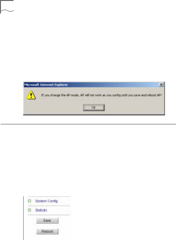
30 Chapter 4 Web-based Configuration Introduction
- <Apply>: Presses to apply a configuration changes. Some
configurations are applied only after saving and rebooting
the AP. A corresponding prompt window will be popped up.
- <Refresh>: refreshes the interface.
- <Default>: restores the default parameters.
Figure 16 AP Reboot Prompt Window
Save and Reboot
Access Method:
Located on the bottom of the left function panel
Interface:
Figure 17 Save and Reboot

Chapter 4 Web-based Configuration Introduction 31
Description:
- Press <Save> to save the system configuration changes
- Press <Reboot> to apply the configuration. This is similar
to the <Reset> button in the equipment
Note: Click <Save> to save the configuration changes even if it
has been applied by clicking <Apply>

5 Web-based Configuration
This chapter introduces all Web-based configuration steps.
• Guide-based configuration operations
• Functional menu-based operations in Basic and Advanced
configuration modes
• Figure 18 lists all configurable items in Basic Config
• Figure 19 and Figure 20 list all configurable items in
Advanced Config
The following section describes these items in detail
5

34 Chapter 5 Web-based Configuration
Figure 18 Basic Configuration
Basi c
Conf i gur at i on
Basi c Mode Wi rel ess 1 WAN LAN DHCP
Br i dge /
Rout e
Wi rel ess port 1
mode 11a/b/g Wi r el ess port 2
Mode ( opt i on)
Wi r el ess 2
(opti on)
SSID
Channel
WEP enabl e/
di sabl e
WEP key
Key t ype
Key 1
Key 2
Key 3
Key 4
SSID
Channel
WEP enabl e/
di sabl e
WEP key
Key t ype
Key 1
Key 2
Key 3
Key 4
Dynamic/
St at i c IP
St at i c I P
address
St at i c I P
mask
Def aul t
Rout e
IP address
IP Mask
DHCP s er v e r/
Rel ay/ None
IP address
Cl i ent t rus t
Gat away
IP Mask
DNS s er ver
Excl ude IP
address
Lease ti me
Manual bi nd
DHCP s er ver
host
Enabl e/
Di s a bl e
Enabl e/
Di s a bl e
Save
conf i gurat i o
n
Aut o c onf i g
enabl e/
di sabl e
Reboot

Chapter 5 Web-based Configuration 35
Figure 19 Advanced Configuration Part I
Advance
configuration (1)
MAC ARP NAT Wireless port 1
performance
Wireless port 2
performance
MAC filter
Enable/Disable
Black lis t
Write list
Boradcast limit
MAC age
IP route
ARP en try Enable /
Disable
Basic/NAPT
Start IP/ End IP
map
redirect
timeout
Beacon Interval
DTIM interval
Power
Bas ic rate
TX rate
fragment
threshold
rts/cts
threshold
Beacon Interval
DTIM interval
Power
Basic rate
TX rate
fragment
threshold
rts/cts
threshold
Isolation
Filter
Static MAC
Route

36 Chapter 5 Web-based Configuration
Figure 20 Advanced Configuration Part II
Advance (2)
Authentication RADIUS Client SMS Wireless 1
WDS
Wireless 2
WDS
DOT1X enable/
disable
Initialize
Max-request
Re-
authentication
Re-authenticate
Re-authperiod
Server timeout
Supplicant
timeout
Tx-period
Quite period
Host server
Accounting key
Authentication
key
Dead time
retransmit
Time out
Dynamic user
Static user
WDS enable/
disable (PTP/
PTMP)
Peer MAC
WDS enable/
disable (PTP/
PTMP)
Peer MAC
MAX request
times
Authentication
mode
Encryption
mode Max online user
Guide Configuration
Objective:
Use AP quickly through the Guide-based configuration system
Detailed Instructions:
1. Click the “Guide” link on the left panel
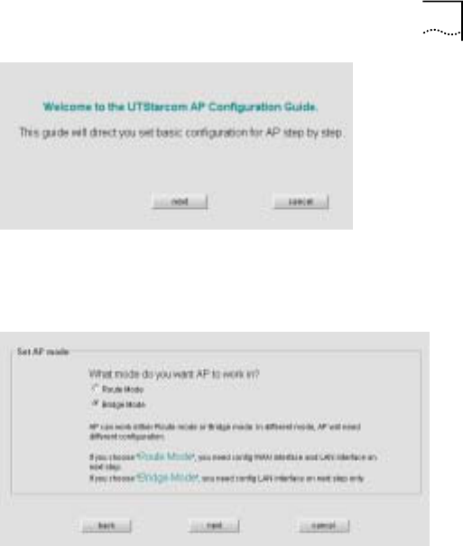
Chapter 5 Web-based Configuration 37
2. Click <next>, set AP operation mode to “Bridge Mode”
Description:
If AP is used as Layer 2 bridging, choose the Bridge mode. If
AP involves in Layer 3 communication, choose the Router
mode.
1. Click <next> to set LAN interface IP address, the default
address is 172.18.37.1/255.255.255.0
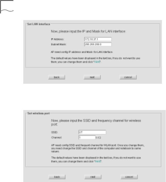
38 Chapter 5 Web-based Configuration
2. Click <next> to set wireless SSID and Channel, the
default SSID is “UT” and the default channel is “1”
Description:
In a planned AP wireless network, SSID is a service ID which is
assigned to the AP by the system administrator. Only a wireless
network card with a configured ESSID can get connection from
the AP. ESSID has the maximum of 32 characters. Wireless
Chapter 5 Web-based Configuration 39
channel is normally set to 1, 6, 11 or 1, 7, 13, hence the
interaction is reduced in most of the situations.
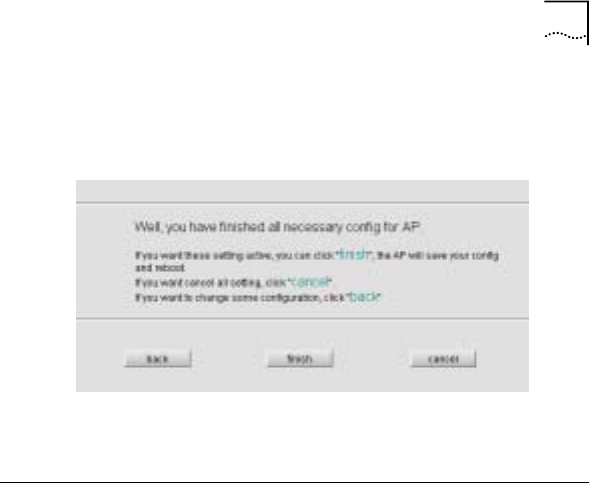
1. Click <next> to complete the Guide configuration
2. Click <finish> to save the configuration, click <cancel>
to keep the current configuration
Wireless Port Configuration
Objective 1:
Wireless port parameters settings in “Basic Config”
Access Method:
Click the “Basic Config/Wireless Port” link on the left panel
Interface:
40 Chapter 5 Web-based Configuration
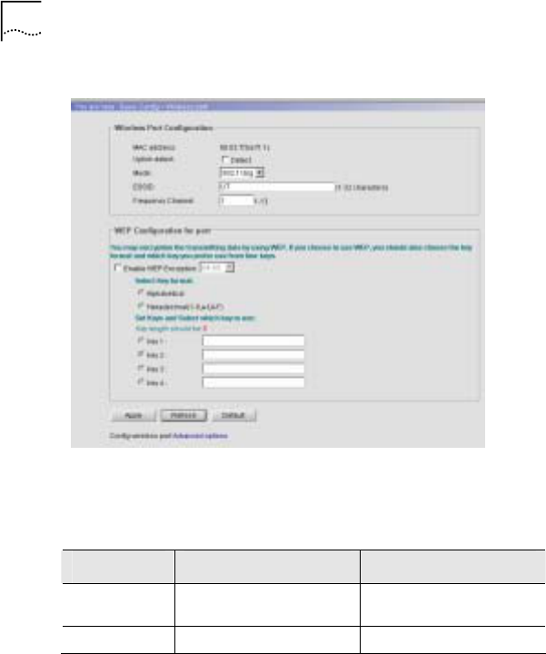
Figure 21 Basic Config - Wireless Port Config
Description:
Table 5 Wireless Port 1 Interface Specification
Field Description Default Value
MAC
Address Wireless network card
MAC address /
Uplink Detect Detect the uplink Disabled

Chapter 5 Web-based Configuration 41
Field Description Default Value
ESSID ESSID is a service ID
assigned to an AP by
the system admin. Only
a wireless network card
with a configured
ESSID can get
connection from AP.
ESSID has maximum of
32 characters
UT
Mode 3 optional modes are
802.11b/g, 802.11b and
802.11g. Select b/g
compatible mode to get
connection through
traditional wireless
network card in b mode
802.11b/g
Frequency
Channel Display AP’s current
channel.
1
WEP Description:
By default, WEP encryption is disabled. User can choose any
one of the two available encryption modes
- WEP-64
- WEP-128
The system provides 4 groups of encryption keys. User can
select any one of 2 key formats
- Alphabetical

42 Chapter 5 Web-based Configuration
- Hexadecimal
Table 6 WA3001 WEP Encryption Configuration
Encryption
Mode Alphabetical HEX
WEP-64 Uses any 5
alphanumeric
characters
between “a-z”,
“A-Z” and “0-9”.
E.g. MyKey
10 hexadecimal digits between “a-f”,
“A-F” and “0-9” with prefix “0x”
E.g. 0x11AA22BB33
WEP-128 Uses any 13
alphanumeric
characters
between “a-z”,
“A-Z” and “0-9”.
E.g.
MyKey12345678
26 hexadecimal digits between “a-f”,
“A-F” and “0-9” with prefix “0x”
E.g.0X00112233445566778899AABBCC
Objective 2:
Wireless Port advanced parameter settings in “Advanced
Config”
Access Method:
Click “Advanced Config/Wireless Port” on the left panel
Interface:
Chapter 5 Web-based Configuration 43
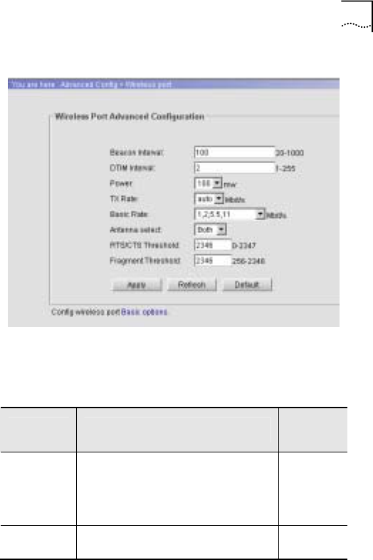
Figure 22 Wireless Port Configuration
Description:
Table 7 Wireless Port 2 Interface Specification
Field Description Default
Value
Beacon
Interval Interval between Beacon packets;
the Beacon packet contains
network card information, duration
of broadcast to the wireless
network.
100(ms)
DTIM
Interval Interval between Delivery Traffic
Indication Message 2(ms)

44 Chapter 5 Web-based Configuration
Field Description Default
Value
Power Transmitting power of the AP
wireless port.
Possible values are: 10mw, 20mw,
50mw, 100mw
100mw
Tx Rate Transmission rate.
The range of selectable values is
decided based on the wireless
mode set in the basic config. If
Auto is chosen, the network card
will select the current optimum
rate.
Possible values are: 11Mbit/s,
5.5Mbit/s, 2Mbit/s, 1Mbit/s, Auto.
auto
Basic Rate The network card is restricted to
operate at the selected Tx rates. 1, 2Mbit/s
Antenna Possible values are: Both, Ant A,
Ant B
Note: From the front view of AP,
left is Ant A, right is Ant B
Both
RTS/CTS
Threshold Request To Send/Clear To Send
mechanism is used in WLAN;
RTS/CTS threshold is
configurable; When a data
package size exceeds the
threshold, choose a setting within
a range of 0-2347. Suggestion: do
not modify the value
2347

Chapter 5 Web-based Configuration 45
Field Description Default
Value
Fragment
Threshold Fragment Threshold mechanism is
used to improve the efficiency in a
high volume wireless network. It
defines the limit of data packages
size. Any package with bigger size
than the value will be fragmented
into several smaller packages
within a range of 256-2346 bytes.
Suggestion: do not modify the
value
2346
User can configure all items in table 5-3, but usually “Antenna”,
“Power” and “Tx Rate” are configurable. The rest of the items
are not recommended to configure
Note: The system provides shortcuts between “Basic Config”
and “Advance Config” interfaces for wireless port
DHCP Server Configuration
Objective:
WAN gets IP address via DHCP Server and DHCP Relay
when AP works in Router Mode
Access Method:
Click the “Basic Config/DHCP Server” link on the left panel
46 Chapter 5 Web-based Configuration
Interface:
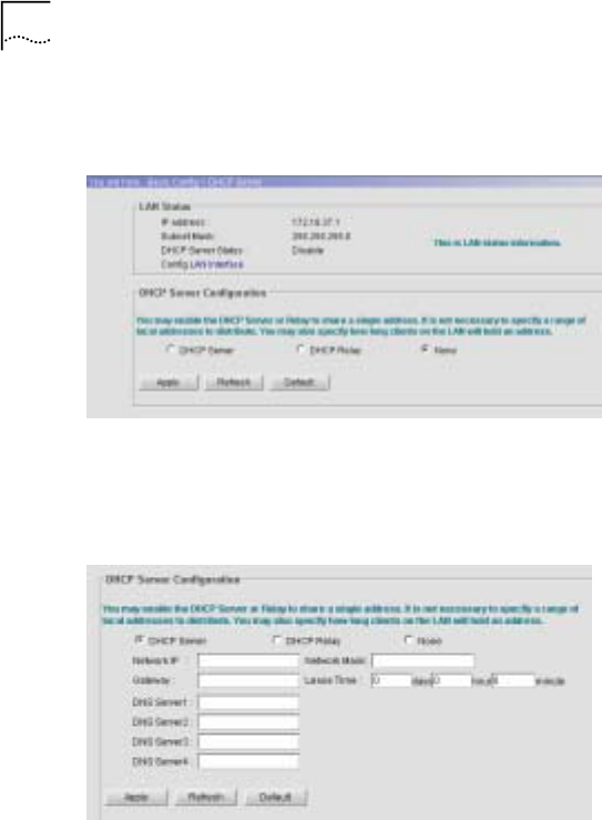
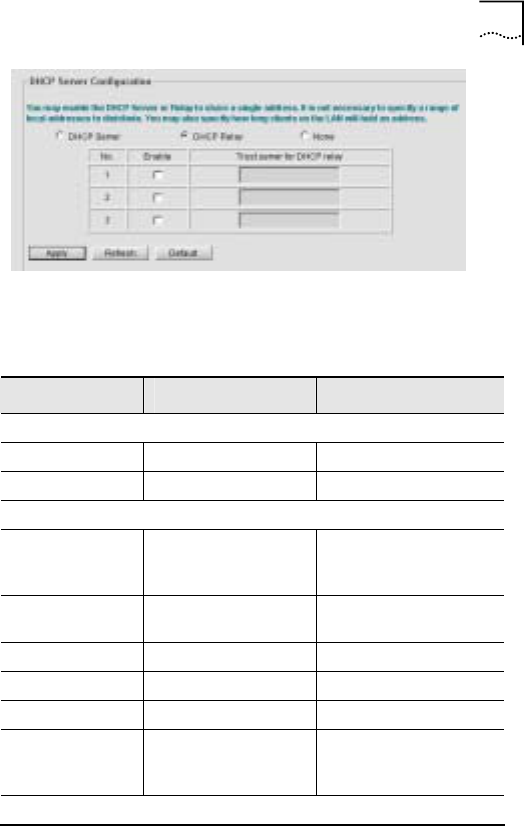
Figure 23 DHCP Server Configuration
Detailed Instructions:
- When DHCP Server is enabled, the system automatically
displays the following configuration interface
- When DHCP Relay is enabled, the system automatically
displays the following configuration interface
Chapter 5 Web-based Configuration 47
Table 8 DHCP Server Configuration Specification
Field Description Default Value
LAN Status
IP Address IP address 172.18.37.1
Subnet Mask Subnet mask 255.255.255.0
DHCP Server Configuration
Use DHCP
Server Enable/Disable
DHCP server
options
Disable
Network IP IP address of
DHCP address pool
Network Mask Network mask
Lease Time Lease Time
Gateway Gateway
DNS Server1-4 DNS Server(s),
total 4 servers can
be set
DHCP Relay Configuration

48 Chapter 5 Web-based Configuration
Field Description Default Value
Trusted DHCP
Server1-3 Trusted DHCP
server settings,
total 3 servers
can be set
Description:
When DHCP Server is enabled
- When DHCP server is enabled, it allocates IP address to a
Client or AP through LAN port
- The subnet mask of DHCP Server IP address pool must be
less than the network mask used in LAN interface
- Able to allocate maximum of 1024 addresses from IP
address pool, including reserved addresses
When DHCP Relay is enabled
- Normally AP connects to remote DHCP server via WAN, in
this case, users must require a certificate for LAN
configuration
- Recommendation: When Relay is enabled, AP directly
connects to DHCP server
WAN Interface Configuration
Objective:
Chapter 5 Web-based Configuration 49
Configure WAN interface when AP is in Router mode
Access Method:
Click the “Basic Config/WAN Interface” link on the left panel
Interface:
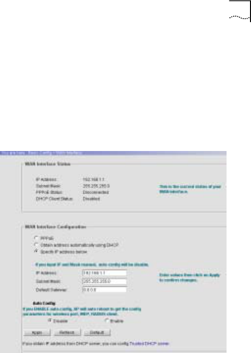
Figure 24 WAN Port Configuration Interface

50 Chapter 5 Web-based Configuration
Table 9 WAN Interface Configuration Specification
Field Description Default Value
WAN Interface Status
IP address IP address 192.168.1.1
Subnet mask Subnet mask 255.255.255.0
PPPoE Status PPPoE Status Disconnected
DHCP Client
Status DHCP Client
Status Disabled
WAN IP Address Configuration
IP Address
Obtain
Methods
1. PPPoE mode
2. Obtain address
automatically using
DHCP
3. Specify IP
address below
Specified IP address mode;
IP Address: 192.168.1.1
Subnet Mask: 255.255.255.0
Auto Configuration
Auto config Enable or Disable
auto configuration
for WAN Interface
Enable “Auto
Config” to have
WAN interface
obtained IP
address from
DHCP server. AP
will get its
configuration
information from
DHCP server after
reboot
Disable
Chapter 5 Web-based Configuration 51
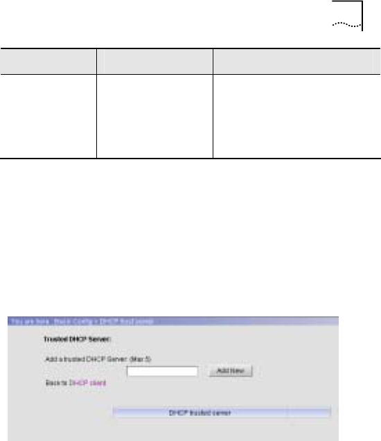
Field Description Default Value
Config Trusted
DHCP Server Perform Trusted
DHCP Server
Configuration to
obtain IP address
through DHCP
server
Detailed Instructions:
Click the “Trusted DHCP Server” link to show the following
configuration interface
Figure 25 Trusted DHCP Server Configuration
Description:
Up to 5-trusted DHCP servers can be configured
In Figure 25, enter DHCP server’s IP address into the input field.
Press <Add New> to add or press <Remove> to delete
52 Chapter 5 Web-based Configuration
LAN Interface Configuration
Objective:
User needs to perform LAN interface configuration regardless
AP working mode.
Access Method:
Click the “Basic Config/LAN Interface” link.
Interface:
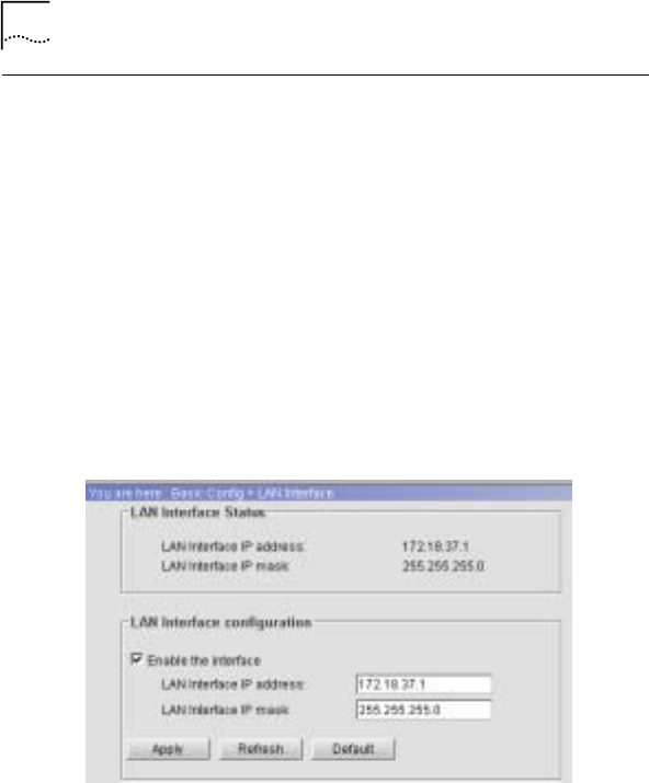
Figure 26 LAN Interface Configuration
Interface Description:

Chapter 5 Web-based Configuration 53
Table 10 LAN Interface Specification
Field Description Default Value
LAN Interface
Enable the
interface Enable the interface Enable
IP address IP address 172.18.37.1
Subnet mask Subnet mask 255.255.255.0
Radius Client
Objective:
Provides accounting service to AP subscribers when AP is in
Router mode.
Access Method:
Click the “Advanced Config/Radius Client” link on the left panel.
Configuration Interface:
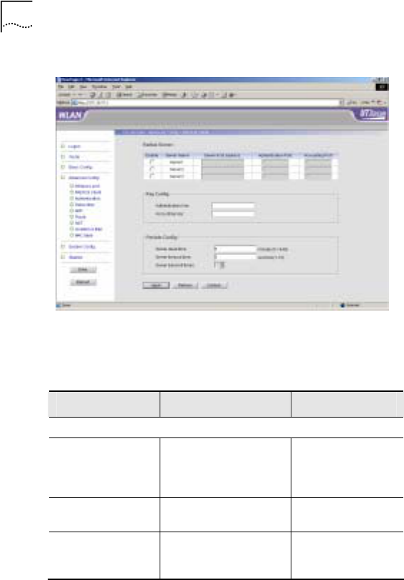
54 Chapter 5 Web-based Configuration
Figure 27 Radius Client Configuration Interface
Interface Description:
Table 11 Radius Client Configuration Specification
Field Description Default Value
Radius Server
Enable Server1-3 Enable or disable
Radius server, up to
3 servers can be
configured
Disable
Server host
address Server host address
Authentication
Port Authentication Port
between AP and
Server
0

Chapter 5 Web-based Configuration 55
Field Description Default Value
Accounting POrt Accounting Port
between AP and
Server
0
Key Config
Authentication
Key Authentication Key
between AP and
Server
Accounting Key Accounting Key
between AP and
Server
Periods Config
Server dead time 5 minutes
Server timeout
time 5 seconds
Server transmit
times
If the request sent to
the Radius Server
does not get a
response within
Timeout value, the
request is re-sent to
the server until the
number of re-tries
reaches the value set
in the Transmit
Times. If any re-try
does not get a
response, then the
AP considers that the
Radius server failed.
It will wait a period of
time as defined in the
Dead Time. Then the
AP will re-send a
request.
3 times
802.1x Authentication
Access Method:

56 Chapter 5 Web-based Configuration
Click the “Advanced Config/Authentication” link on the left panel
Configuration Interface:
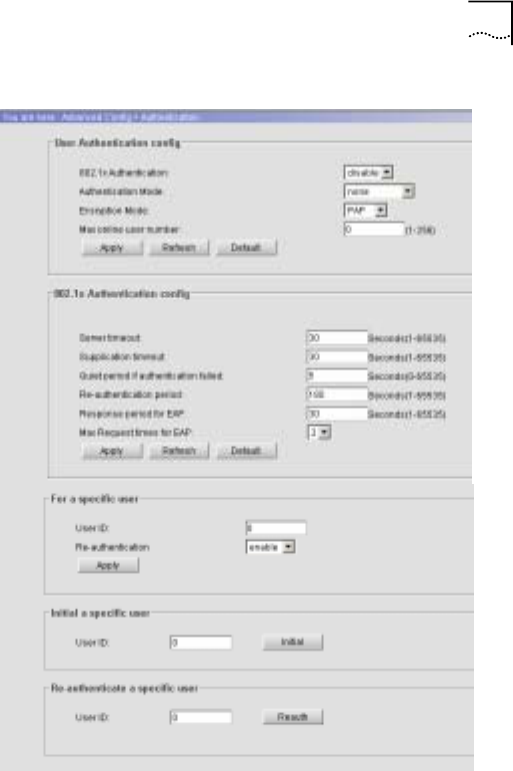
Chapter 5 Web-based Configuration 57
Figure 28 802.1x Authentication Configuration
Interface Description:

58 Chapter 5 Web-based Configuration
Table 12 802.1x Configuration Specification
Field Description Default Value
User Authentication Config
802.1x
Authentication Enable or Disable
802.1x Authentication disable
Authentication
Mode Authentication mode
options: none, local,
remote, local-remote,
remote-local
none
Encryption Mode Encryption mode
between wireless
terminals and AP.
Options: CHAP, PAP
PAP
Max online user
number Max online user number.
Options: 1-256 0
802.1x Authentication Config
Parameter Specification Default
Server timeout
Interval between retries
of sending a request
frame from AP to Server
(second). If within the
Timeout period the
Server doesn’t respond
to the AP’s request, the
AP will re-send the
request frame. Possible
values: 1-65535
seconds.
30

Chapter 5 Web-based Configuration 59
Field Description Default Value
Supplication
timeout
Interval between retries
of sending a request
frame from AP to Client
(second). If within the
Timeout period the
Client does not respond
to the AP’s request, the
AP will re-send the
request frame. Possible
values: 1-65535
seconds.
30
Quiet period if
authentication
failed
If the user name or
password failed because
of authentication, the AP
will not process the
authentication request
from the Client within
Quiet-period value.
Possible values: 1-
65535 seconds.
5
Response period
for EAP
Interval of AP sending
Request-challenge
request to the client
under EAP
authentication (Re-
sending because the
Response-challenge was
not received). Possible
values: 1-65535
seconds.
30

60 Chapter 5 Web-based Configuration
Field Description Default Value
Max Request
times for EAP
Maximum number of
retries to send a
Request-challenge
request from AP to client
under EAP
authentication (Re-
sending because the
Response-challenge was
not received). Possible
values: 1-2.
2
For a specific user
User ID User ID, the system
automatically generates
a unique id when adding
a new user
Re-authentication Enable or Disable Re-
authentication
Initial a specific user
User ID User ID
Re-authenticate a specific user
User ID User ID
UI buttons
Apply Configurations take
effect
Refresh Refresh selections
Restart Authentication
parameters take effect
Initial Initialize configurations
Re-auth Force user to re-
authenticate

Chapter 5 Web-based Configuration 61
Description:
Available Functionality:
- Global user configuration parameters (LAN interface and
Wireless connected clients), e.g. enable or disable 802.1x
authentication, authentication mode, encryption mode, max
online user number
- Global 802.1x authentication, Server-AP-Client
authentication parameters configuration
- Specify authenticated users, initialize authenticated users
and re-authenticated users
User Management
Objective:
After 802.1x authentication is enabled, AP is able to manage
both dynamic and static users. Dynamic users require
authentication whereas Static users do not require
authentication.
Dynamic Users
Access Method:
Click the “Advanced Config/Subscriber” link on the left panel,
then choose “Dynamic user”
Configuration Interface:
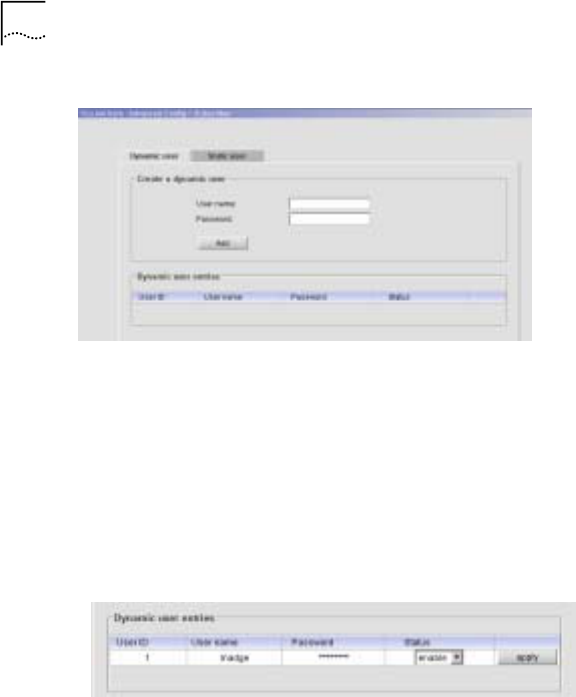
62 Chapter 5 Web-based Configuration
Figure 29 Dynamic User Configuration Interface
Configuration Description:
Detailed Instructions:
• Add a new dynamic user
Enter User name and Password, and then click <Add>. A
new entry will be added in the table as shown below. User
ID is automatically generated by the system.
• Enable, disable or delete dynamic users
Select the option from the Status drop-down box to
manage dynamic users
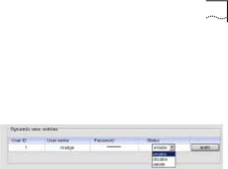
Chapter 5 Web-based Configuration 63
Enable: enables a specific dynamic user and allows
the user to access
Disable: disables a specific dynamic user and
prohibits the user access
Delete: deletes a specific dynamic user and removes
the user information from the database
Static Users
Access Method:
Click the “Advanced Config/Subscriber” link on the left panel,
choose “Static user”
Configuration Interface:
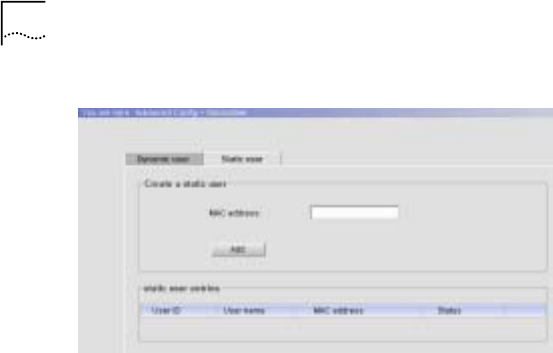
64 Chapter 5 Web-based Configuration
Figure 30 Static User Configuration Interface
Configuration Description:
Detailed Instructions:
• Add a new static user
Enter static user’s PC MAC address, and then click <Add>. A
new user entry will be added in the table as shown below. User
ID is automatically generated. User name is identical to MAC
address
• Enable or disable static users
Select the option from the Status drop-down box to manage
static users
Enable: enables a specific static user and allows the
user to access
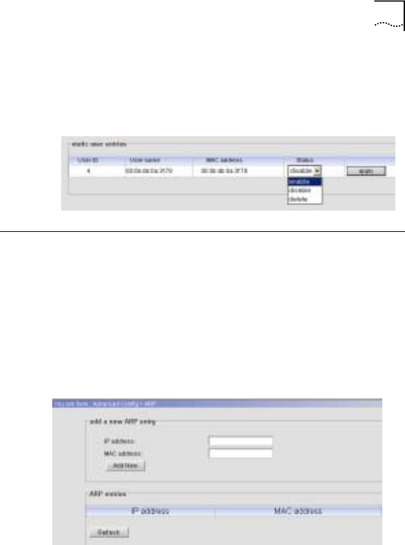
Chapter 5 Web-based Configuration 65
Disable: disables a specific static user and prohibits
the user access
Delete: deletes a specific static user and removes the
user information from the database
ARP Management
Access Method:
Click the “Advance Config/ARP” link on the left panel
Configuration Interface:
Figure 31 ARP Configuration Interface
Configuration Description:
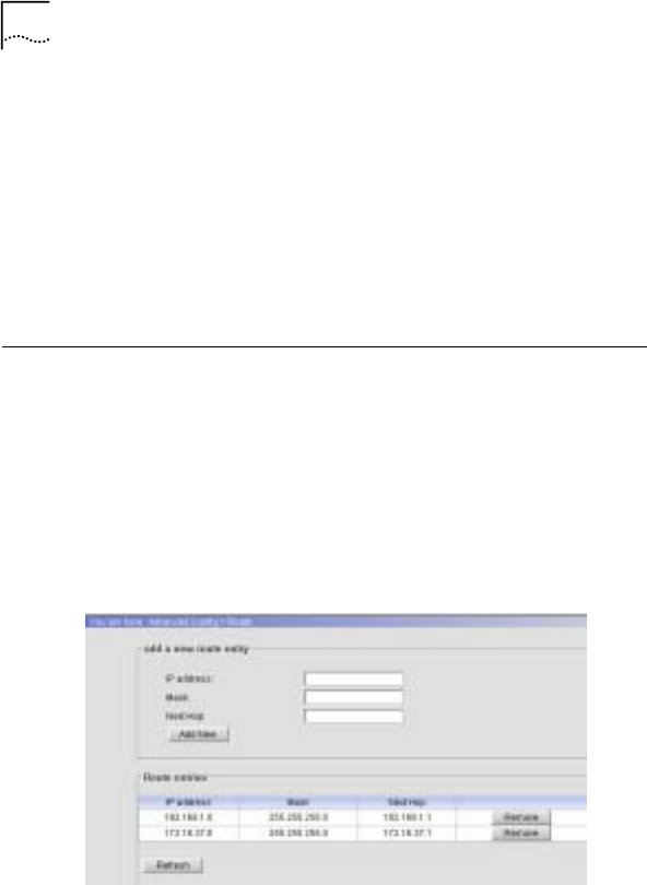
66 Chapter 5 Web-based Configuration
Refer to the detailed instructions given below to speed up AP
data transmission through configure the static ARP table.
• Add a new ARP entry
Enter IP address, MAC address, and then click <Add New>
• Remove ARP
Click <Remove> to delete one ARP entry
Route Configuration
Access Method:
Click the “Advanced Config/Route” link on the left panel
Configuration Interface:
Figure 32 Route Configuration Interface
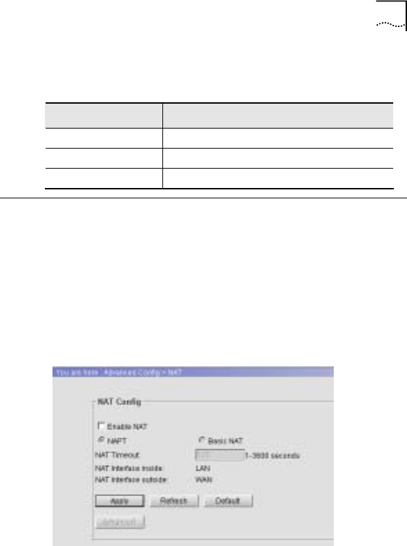
Chapter 5 Web-based Configuration 67
Interface Description:
Figure 33 Table 5-1 Route Configuration Interface Spec
Field Description
IP address Route’s beginning IP address
Mask Route’s beginning Subnet mask
Next Hop Route’s next hop address
NAT Configuration
Access Method:
Click the “Advanced Config/NAT” link on the left panel
Configuration Interface:
Figure 34 NAT Configuration Interface
Interface Description:

68 Chapter 5 Web-based Configuration
Figure 35 Table 5-2 NAT Configuration Specification
Field Description Default Value
Enable NAT Enable or Disable NAT Disable
NAT Mode Two NAT modes are
available after enable NAT,
NAPT mode and Basic
NAT mode
NAPT
NAT Timeout NAT timeout options: 1-
3600 seconds 120
NAT Interface
inside NAT Interface inside LAN Port
NAT Interface
outside NAT Interface outside WAN port
Configuration Description:
When NAT is enabled, select NAPT mode. Click <Apply> to
apply the configuration and click <Advanced> to take effect. For
more details, refer to the section 5.11.1 to configure the IP
address based mapping and port based mapping.
When NAT is enabled, select Basic mode. Click <Apply> to
apply the configuration and click <Advanced> to take effect.
User should configure the link between “NAT Pool” and “NAT
Static Map” based on port.
NAPT Mode
Access Method:
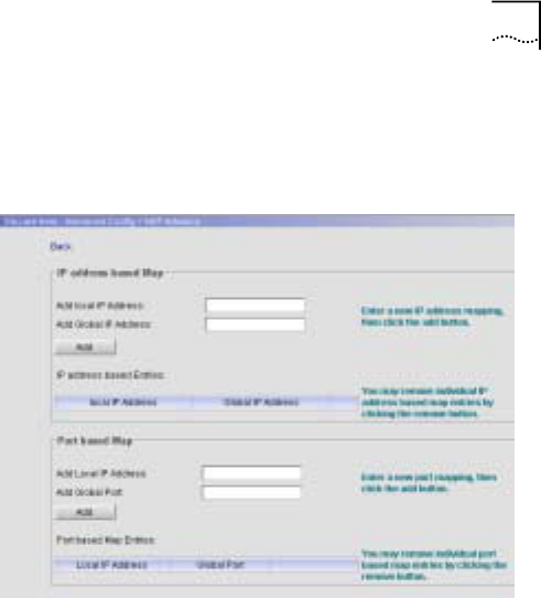
Chapter 5 Web-based Configuration 69
Click the “Advanced Config/NAT Advance” link, then click “NAT”
on the left and click “NAT Pool” on the right
Configuration Interface:
Configuration Description:
Detailed Instructions:
• Add a port based MAP
Input the values in the “Add Local IP Address”, “Add Global
Port” fields, click <Add>
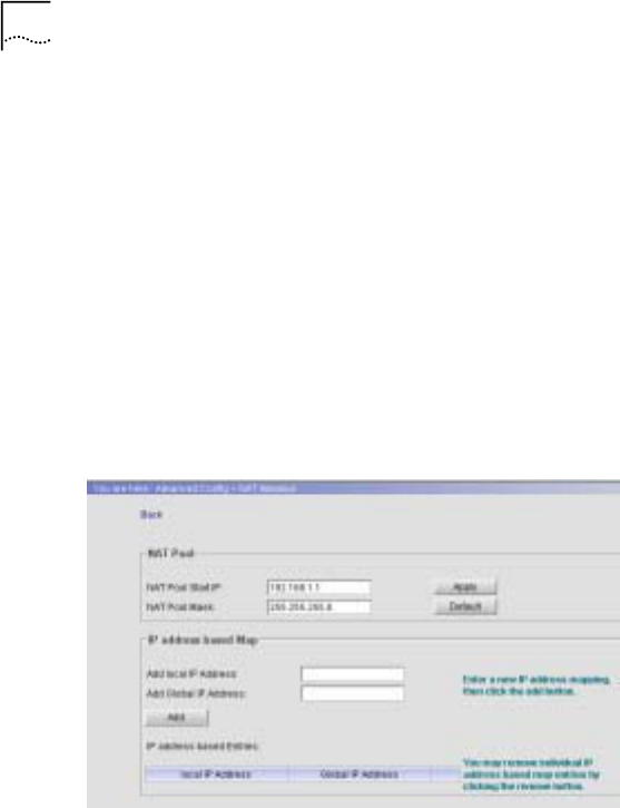
70 Chapter 5 Web-based Configuration
• Delete a port based MAP
Press <Remove> to delete a port based MAP
Basic NAT Mode
Access Method:
Click the “Advanced Config/NAT Advance” link, then click “NAT”
link on the left, click “NAT Static Map” link on the right
Configuration Interface:
Figure 36 NAT Static MAP Configuration Interface
Configuration Description:
Detailed Instructions:

Chapter 5 Web-based Configuration 71
• Change NAT address pool
Input the values in the “NAT Pool Start IP” and “NAT Pool
Mask” fields, and then click <Apply>
• Add new IP Address based static MAP
Input the values in the “Add local IP Address” and “Add
Global IP Address” fields, then click <Add>
• Delete static MAP
Click <Remove> to delete a static MAP
Isolation&filter Configuration
Access Method:
Click the “Advanced/MAC Filter” link on the left panel
Configuration Interface:
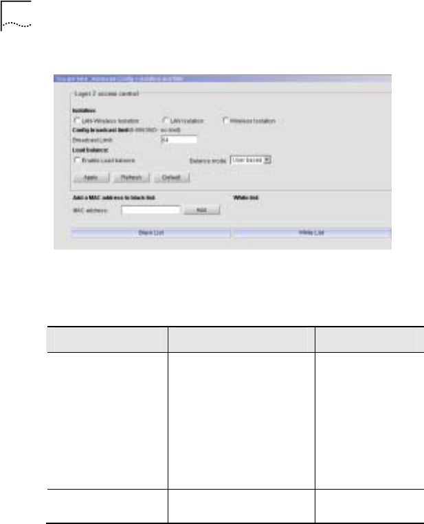
72 Chapter 5 Web-based Configuration
Figure 37 Isolation&filter Configuration Interface
Interface Description:
Table 13 MAC Filter Configuration Specification
Field Description Default Value
Isolation:
-LAN-Wireless
Isolation
-LAN Isolation
-Wireless Isolation
3 types of isolations:
LAN-wireless isolation
LAN isolation
Wireless Isolation
Disable Isolation
Config broadcast
limit Broadcast limit options:
0-65535。 64

Chapter 5 Web-based Configuration 73
Field Description Default Value
Load balance Two modes of Load
Balance:
User based – based on
the number of AP’s users
Flux based – based on
AP’s throughput
Disable
Add a MAC address
to black List MAC address black list.
The clients in the black
list are not allowed to
access AP
White list MAC address white list.
The clients in the white
list are allowed to access
AP
Configuration Description:
To prevent unauthorized access, or to fulfill the network design
and unnecessary or prohibited MAC address into black list.
When 802.1x authentication configuration adds a new static
user and the status is enabled, this user will be added into white
list automatically. These users do not require authentication to
access AP
MAC Management
Access Method:
Click the “Advance Config/MAC table” link on the left panel
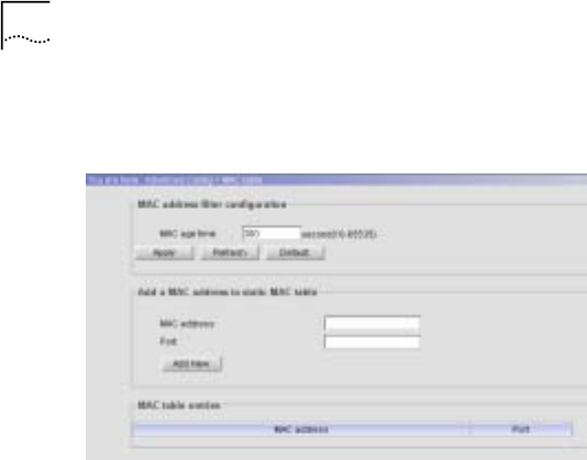
74 Chapter 5 Web-based Configuration
Configuration Interface:
Figure 38 MAC Table Configuration Interface
Configuration Description:
Detailed Instructions:
• MAC Age time:
- Value range: 10-65535
- Default value: 300 seconds
• Add a MAC address to static MAC table:
- MAC address: input format: 00:03:7F:BF:08:80
- Port: Originated port number of the transferred data
- Click <Add New>

Chapter 5 Web-based Configuration 75
• Remove MAC address: click <Remove>

6 Web-based System
Configuration
This chapter primarily covers the following:
• Viewing System Information
• Changing Password
• Managing File System
• Debug Configuration
Viewing System Information
Access Method:
Click “System Config/System” on the left panel.
Configuration Interface:
Figure 39 System Information
6
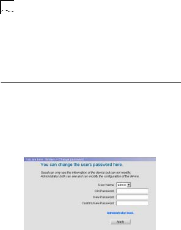
78 Chapter 6 Web-based System Configuration
Description:
The system information includes the following fields:
- Product Serial No.
- Hardware version
- Software version
Changing Password
Access Method:
Click “System Config/Change Password” on the left panel.
Configuration Interface:
Figure 40 Change Password
Description:

Chapter 6 Web-based System Configuration 79
Two types of users can log into the system: admin and guest.
An “admin” has the privilege to perform all operations to the
device, including information browse, configuration and
modification and so on; while a “guest” only has the privilege to
browse information.
An “admin” can modify passwords for all users in the system;
while a “guest” can only modify his own password.
Managing File System
Access Method:
Click “System Config/File System” on the left panel.
Configuration Interface:
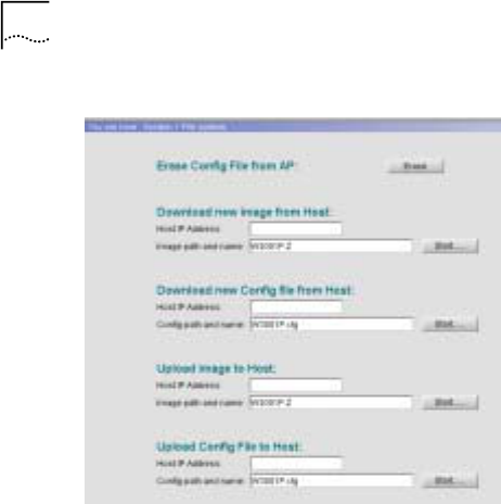
80 Chapter 6 Web-based System Configuration
Figure 41 File System

Chapter 6 Web-based System Configuration 81
Description:
Table 14 File System Window Description
Fields Description
Erase Config File from AP Erases the current configuration file
from the AP.
Download new image from
Host Downloads a new image
(VxWorks.Z) from a host.
Download new Config file
from Host Downloads a new configuration file
from host.
Upload image to Host Uploads an image to a host
Upload Config File to Host Uploads a configuration file to a
host.
Description:
Click <Erase> to erase the current configuration file from the AP;
a dialog box will appear as shown in Figure 42. Click <OK> and
a message box will appear as shown in Figure 43. It prompts
the rebooting device and initiates the configuration erase.
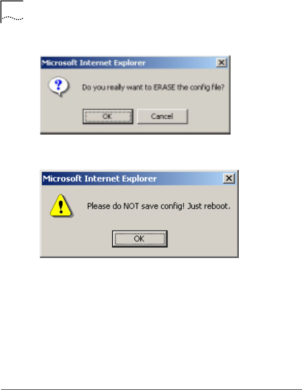
82 Chapter 6 Web-based System Configuration
Figure 42 Confirm Configuration File Erase
Figure 43 Initiating Configuration File Erase Message
Click <OK> to confirm the erasing; click <Reboot> to reboot the
system and initiate the configuration. Do not click <Save> on
the left to save the configuration.
For system file (including image and configuration file)
management, specify the host IP address and the system file
path and file name. Currently, the configuration file only
supports TXT format.
Debug Configuration
Access Method:

Chapter 6 Web-based System Configuration 83
Click “System Config/Debug Config” on the left panel.
Configuration Interface:
Figure 44 Debug Configuration
Description:
Through debug configuration, the user can view the following
information via CLI and SNMP:
Configurable items are: 802.1X, SMI, RADIUS Client, DHCP
Client, DHCP Server, DHCP Relay, IP Stack, NAT, Bridge,
802.1 and Web.
Configurable types are: Error, Warning and Trace.

7 Performance Statistics
Interface Statistics
Access Method:
Click “Statistic/Interface” on the left panel.
Configuration Interface:
7
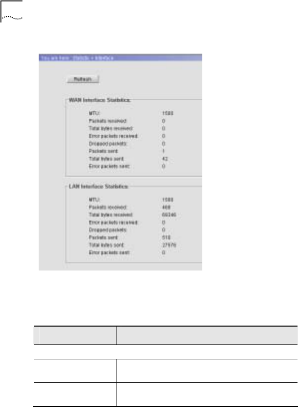
86 Chapter 7 Performance Statistics
Figure 45 Interface Statistics
Table 15 Interface Statistics Window Description
Fields Description
WAN/LAN Interface Description
MTU (Maximum
Transmission Unit) Packets in MS are based on Ethernet
standards. The MTU value is 1500.
Packets received Number of packets received via the
WAN/LAN interface.

Chapter 7 Performance Statistics 87
Fields Description
Total bytes
received Total number of bytes received via the
WAN/LAN interface.
Error packets
received Number of error packets received via the
WAN/LAN interface.
Dropped packets Number of packets dropped by the WAN/LAN
interface.
Packets sent Number of packets sent from the WAN/LAN
interface.
Total bytes sent Number of bytes sent from the WAN/LAN
interface.
Error bytes sent Number of error bytes sent from the
WAN/LAN interface.
Button
Refresh Click this button to retrieve the latest
statistics of the system.
DHCP Server Statistics
Access Method:
Click “Statistic/DHCP Server” on the left panel.
Configuration Interface:
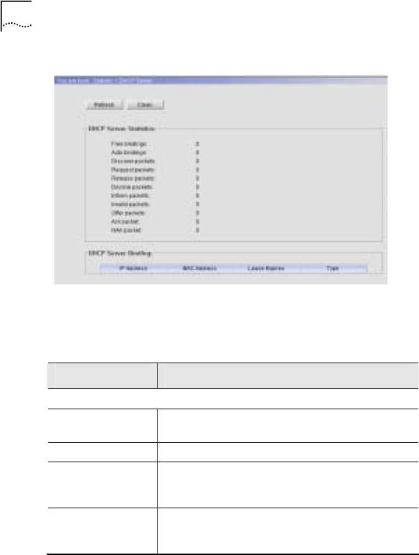
88 Chapter 7 Performance Statistics
Figure 46 DHCP Server Statistics
Description:
Table 16 DHCP Server Statistics Window Description
Fields Description
DHCP Server Statistics
Free bindings Number of Free Binding IP addresses provided
by the DHCP server.
Auto bindings Number of Auto Binding IP addresses.
Discover packets Number of Discovery packets received from
the DHCP workstation by the DHCP server
during the discovery period.
Request packets Number of Request packets received from the
DHCP workstation by the DHCP server during
the selection period.

Chapter 7 Performance Statistics 89
Fields Description
Decline packets Number of Decline packets received from the
DHCP workstation by the DHCP server during
the selection period.
Inform packets Number of Inform packets of configuration
information request sent from the DHCP
workstation to the DHCP server.
Invalid packets Number of invalid communication packets
between the DHCP workstation and the DHCP
server.
Offer packets Number of Offer packets sent from the DHCP
server to the DHCP workstation during the
offer period.
Ack packets Number of Ack packets sent from the DHCP
server to the DHCP workstation during the
acknowledge period.
NAK packets Number of NAK (negative acknowledgement)
packets sent from the DHCP server to the
DHCP workstation during the acknowledge
period.
DHCP Server Bindings
IP Address IP address bound to a MAC address in the
DHCP server.
MAC Address MAC address bound to an IP address in the
DHCP server.
Lease Expires The lease expiration time of the bound
address.
Type Type of bound address, e.g. Manual, Auto
Buttons
Refresh Click this button to retrieve the latest statistics
of the system.

90 Chapter 7 Performance Statistics
Fields Description
Clean Click this button to clean the statistics of the
system.
Theory:
DHCP service operation theory:
The communication method between the DHCP workstation
and server is depending upon whether it is the first time that the
DHCP workstation logs into the network. Consider the following
situation as an example when the DHCP workstation logs into
the network for the first time:
The first period is a discovery period when the DHCP
workstation discovers DHCP servers. The DHCP workstation
broadcasts the “dhcp discover” messages to search DHCP
servers (DHCP server IP address is not known), i.e., the DHCP
workstation sends specific broadcast information to
255.255.255.255. Every host installed with TCP/IP protocol on
the network will receive such broadcast information. Only DHCP
servers will respond to this broadcast information.
The second period is an offer period when DHCP servers offer
the IP address. DHCP servers will respond when they receive
the “dhcp discover” message and assign an unleased IP
address to the DHCP workstation. Then send the DHCP
workstation the “dhcp offer” message, which includes the IP
address to be leased and other configuration.

Chapter 7 Performance Statistics 91
The third period is a selection period when the DHCP
workstation selects the IP address offered by one DHCP server.
If multiple DHCP servers send “dhcp offer” messages to the
DHCP workstation, the DHCP workstation will accept only the
first received “dhcp offer” message, and broadcast one “dhcp
request” message as response, which includes the selected
DHCP server request IP address. The workstation broadcasts
the “dhcp request” message in order to inform all DHCP servers
that it has selected the IP address offered by one DHCP server.
The fourth period is an acknowledge period when the DHCP
server acknowledges the offered IP address. When the DHCP
server receives the “dhcp request” message responded by the
DHCP workstation, it will send the DHCP workstation a “dhcp
ack” message which includes the offered IP address and other
configurations, informing the DHCP workstation to use the
offered IP address. The DHCP workstation will then bind the
TCP/IP protocol to the network card. All other DHCP servers
except the selected server will take back their offered IP
addresses.
DHCP Relay Statistics
Access Method:
Click “Statistic/DHCP Relay” on the left panel.
Configuration Interface:
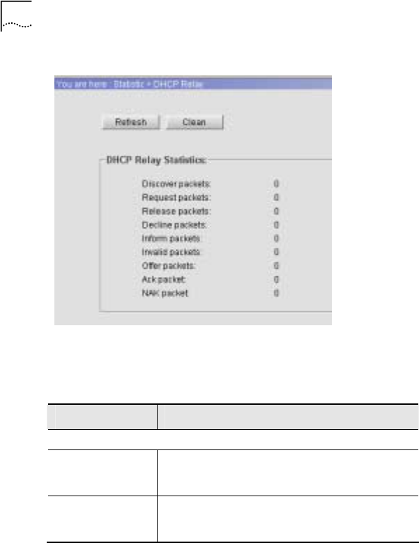
92 Chapter 7 Performance Statistics
Figure 47 DHCP Relay Statistics
Description:
Table 17 DHCP Relay Statistics Window Description
Fields Description
DHCP Relay Statistics
Discover packets Number of Discover packets sent from the
DHCP workstation to the DHCP server via the
AP during the discovery period.
Request packets Number of Request packets sent from the
DHCP workstation to the DHCP server via the
AP during the selection period.

Chapter 7 Performance Statistics 93
Fields Description
Release packets Number of Release packets initiated by the
DHCP workstation, and forwarded by the AP to
the DHCP server, releasing IP addresses used
by DHCP workstation.
Decline packets Number of Decline packets sent from the
DHCP workstation to the DHCP server via the
AP to decline IP address Offer response(s)
from DHCP server(s).
Inform packets Number of Inform packets sent from the DHCP
workstation to the DHCP server via the AP.
Offer packets Number of Offer packets sent from the DHCP
server to the DHCP workstation via the AP
during the Offer period.
Ack packets Number of Ack packets sent from the DHCP
server to the DHCP workstation via the AP
during the acknowledge period.
NAK packets Number of NAK packets sent from the DHCP
server to the DHCP workstation via the AP
during the acknowledge period.
Buttons
Refresh Click this button to retrieve the latest statistics
of the system.
Clean Click this button to clean the statistics of the
system.
RADIUS Client Statistics
Access Method:
Click “Statistic/RADIUS Client” on the left panel.
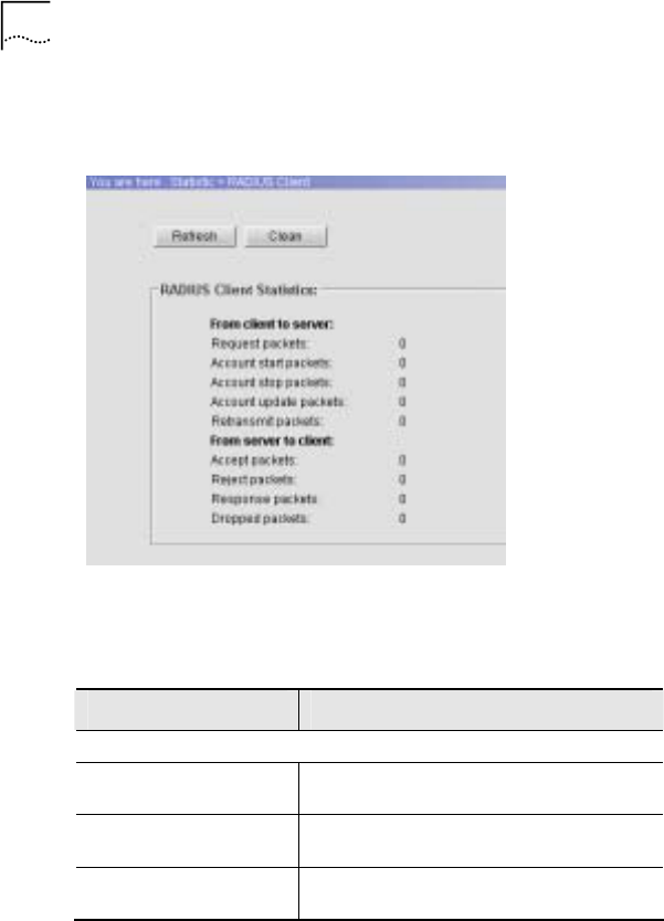
94 Chapter 7 Performance Statistics
Configuration Interface:
Figure 48 RADIUS Client Statistics
Description:
Table 18 RADIUS Client Statistics Window Description
Fields Description
From client to server
Request packets Number of Request packets sent by the
RADIUS Client.
Account start packets Number of Account Start packets sent by
the RADIUS Client.
Account stop packets Number of Account Stop packets sent by
the RADIUS Client.

Chapter 7 Performance Statistics 95
Fields Description
Account update packets Number of Account Update packets sent
by the RADIUS Client.
Retransmit packets Number of retransmitted packets sent by
the RADIUS Client.
From server to client
Accept packets Number of Accept packets received by
the RADIUS Client.
Reject packets Number of Reject packets received by
the RADIUS Client.
Response packets Number of Response packets received
by the RADIUS Client.
Dropped packets Number of Dropped packets received by
the RADIUS Client.
Buttons
Refresh Click this button to retrieve the latest
statistics of the system.
Clean Click this button to clean the statistics of
the system.
ARP Table
Access Method:
Click “Statistic/ARP” on the left panel.
Configuration Interface:
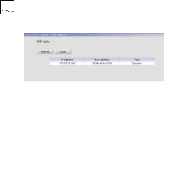
96 Chapter 7 Performance Statistics
Figure 49 ARP Table
Description:
The ARP table fields include IP address, MAC address and
ARP table obtaining type. The type can be “dynamic” or “static”.
The obtaining type is dynamic only when the ARP entry is learnt
during the AP packet forwarding period. The obtaining type is
static only when the ARP entry is added manually.
To prevent the ARP table information from aging, click <Clean>
to maintain the table.
Route Table
Access Method:
Click “Statistic/Route” on the left panel.
Configuration Interface:
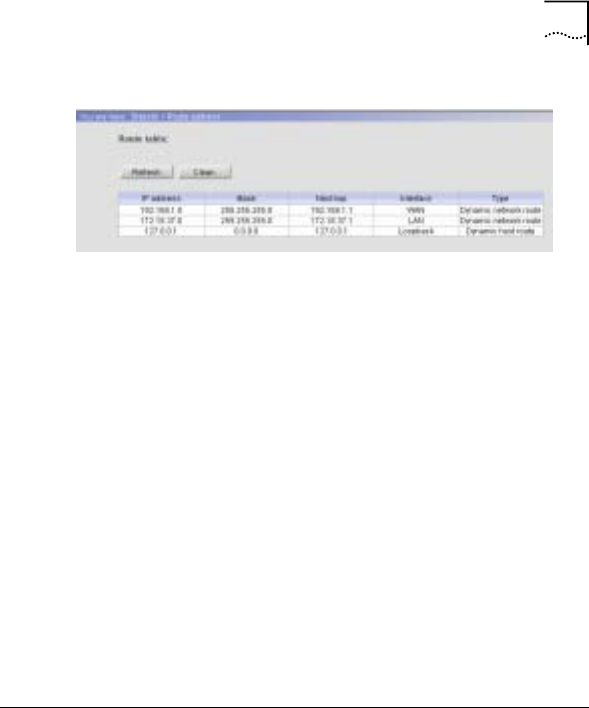
Chapter 7 Performance Statistics 97
Figure 50 Route Table
Description:
The ARP table information in the AP includes the following
fields:
IP address and mask: The destination network segment and its
subnet mask for the route.
Next hop: The IP address of the next hop router’s ingress.
Interface: The egress on the AP from which the route reaches
the destination router.
Type: Dynamic network route or dynamic host route.
Online User Information
Access Method:
Click “Statistic/Online user” on the left panel.
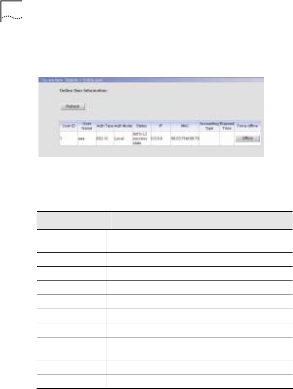
98 Chapter 7 Performance Statistics
Configuration Interface:
Figure 51 Online User Information
Description:
Table 19 Online User Information Window Description
Fields Description
User ID It is a unique ID automatically generated by the
system when adding a new user.
User Name The name of the online user.
Auth Type The authentication type for the online user.
Auth Mode The authentication mode for the online user.
Status The status of the online user.
IP The IP address assigned to the online user.
MAC The MAC address of the online user.
Accounting
Type Accounting type for the online user.
Elapsed Time The total elapsed online time.
Force Offline Click this button to force the user offline.

Chapter 7 Performance Statistics 99
MAC Address
Access Method:
Click “Statistic/MAC address” on the left panel.
Configuration Interface:
Figure 52 MAC Address
Description:
The MAC address information includes the following fields:
MAC address, learning type, forwarding port (WAN port or LAN
port), pass time and age time (aging time for the MAC address).
For example:
The pass time in the first line of the window shown in 錯誤! 找不
到參照來源。 is 0, which means the MAC address is connected
to the AP all the time.

100 Chapter 7 Performance Statistics
In the third line, the age time for the MAC address
“00:04:23:85:39:5e” is 300 seconds, the pass time is 2 seconds,
then the remaining life time for this MAC address is 298
seconds.
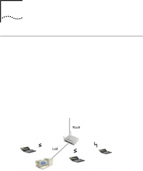
8 Web-based Configuration
Examples
AP in Bridge Mode
Objective:
To establish a wireless network to provide wireless access for
subscribers. The AP works only as a bridge. Data is transmitted
between the AP and clients by WEP encryption.
Network Topology:
Figure 53 Network Topology
Uplink port
Detailed Instructions:
8

102 Chapter 8 Web-based Configuration Examples
1. After completing the hardware installation, launch the
WEB configuration interface.
- According to the above network topology, use a
network cable (straight-through or crossover) to
connect the PC and the AP’s LAN interface. Set the
PC IP address as 172.18.37.X/255.255.255.0. The
default IP address of the AP LAN interface is
172.18.37.1
- Input http://172.18.37.1 in the PC browser. Use
“admin” for both username and password to log in to
the system
2. Set the AP in Bridge mode.
- Click Guide to display the “Set AP Mode” window as
shown below. The default mode is Bridge mode.
- Click <Next> to display the “Set LAN Interface”
window as shown below:
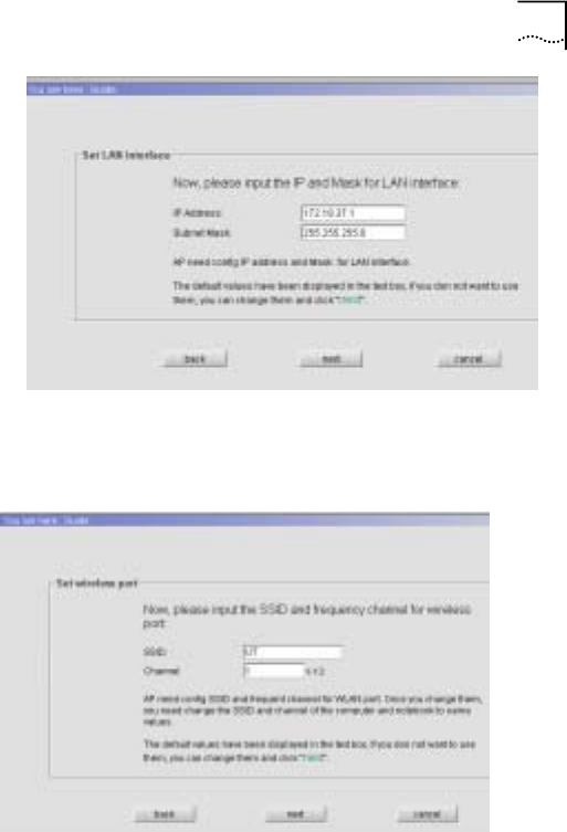
Chapter 8 Web-based Configuration Examples 103
- Configure the IP address for the LAN interface. Click
<Next> to display the “Set Wireless Port” window as
shown below:
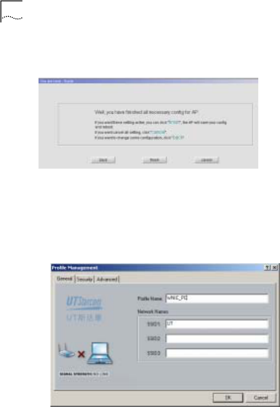
104 Chapter 8 Web-based Configuration Examples
- Configure the SSID for the WLAN port and select a
channel. Default value can also be used. Click <Next>
to display the window as shown below:
- Click <finish>, and the AP will reboot. After the
rebooting is complete, the configuration will be valid
3. Configure the WNIC SSID to enable the communication
with the AP.
- Set the same SSID in WNIC Window IE as in AP
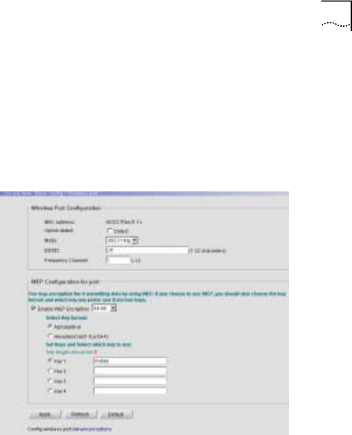
Chapter 8 Web-based Configuration Examples 105
- Now the AP can communicate with the PC
4. Set the WEP encryption between the AP and Client
WNIC.
- Click “Basic Config/Wireless Port” to display the
window as shown below; enable WEP encryption with
64-bit, select “Alphabetical” key format and enter
“mykey” as the key1 value
- Click <Apply>. The system will prompt the user to
save the configuration, and then reboot the AP to
initiate the configuration
- Set “mykey” as the WEP value in WNIC Windows IE
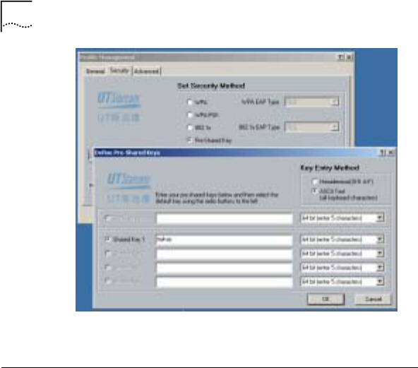
106 Chapter 8 Web-based Configuration Examples
AP in Router Mode (Case 1)
Objective:
To establish a medium-scale network for a company, where the
AP acts as an authenticator, AC as an authentication agent and
the remote server as RADIUS authentication and accounting
server.
The AP obtains the IP address via the remote DHCP server.
The AP will use NAT (Network Address Translation) for
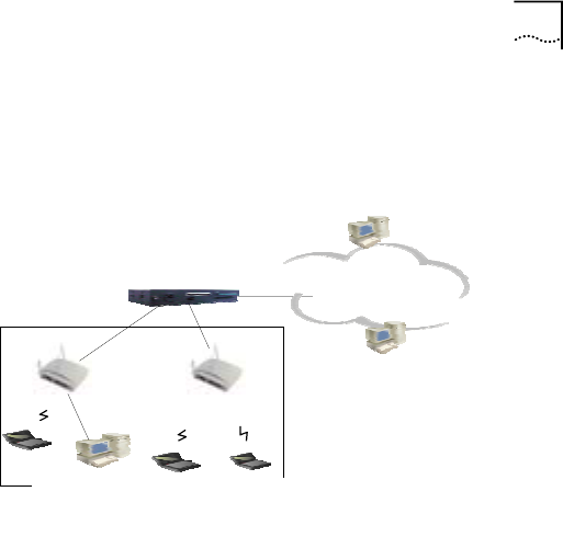
Chapter 8 Web-based Configuration Examples 107
management when it works as a DHCP relay. Configure two
dynamic subscribers and one static subscriber
Network Topology:
上行口
A
AC
C
A
P1
A
P2 DHCP Ser ver
企业大楼
I
I
P
P
M
M
A
A
N
N
Radi us Ser ver
Detailed Instructions: (Consider AP1 as an example)
5. Click “Basic/DHCP Server” to display the “DHCP
Server” window. Enable “DHCP Relay” and configure
the trust server for DHCP relay.
Commercial Building
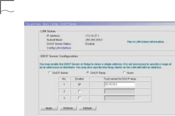
108 Chapter 8 Web-based Configuration Examples
6. Configure 802.1x authentication. Click “Advanced
Config/Authentication” to display the “Authentication”
window. Enable 802.1x authentication, set the
authentication mode to “remote” and set the maximum
number of online users to “10”.
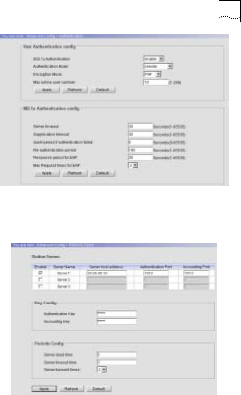
Chapter 8 Web-based Configuration Examples 109
7. Click “Advanced Config/RADIUS Client” to display the
“RADIUS Client” window. Configure the RADIUS server
and its parameters.
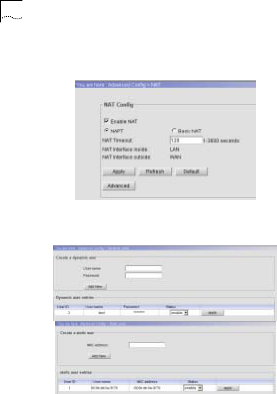
110 Chapter 8 Web-based Configuration Examples
8. Click “Advanced Config/NAT” to display the “NAT”
window. Enable NAT and perform advanced NAT
configuration.
9. Click “Advanced Config/Subscriber” to add dynamic
subscribers and static subscribers.

Chapter 8 Web-based Configuration Examples 111
AP in Router Mode (Case 2)
Objective:
To establish a small-scale network for a company with low
investment and strong functionality. The number of subscribers
is no more than 20.
The BRAS (Broadband Remote Access Server) aggregates the
authentication and accounting information. Enable NAT and
PPPoE server.
AP1 and AP2:
- Enable PPPoE client for WAN interface
- Enable DHCP server for LAN interface in order to assign
addresses for wireless subscribers
- Enable 128-bit WEP encryption
- Enable load balance
- Enable 802.1x local authentication
Network Topology:
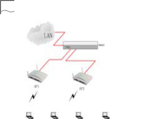
112 Chapter 8 Web-based Configuration Examples
Detailed Instructions: (Consider AP1 as an example)
1. Click “Basic Config/WAN Interface” to display the “WAN
Interface” window. Enable PPPoE.
BRAS
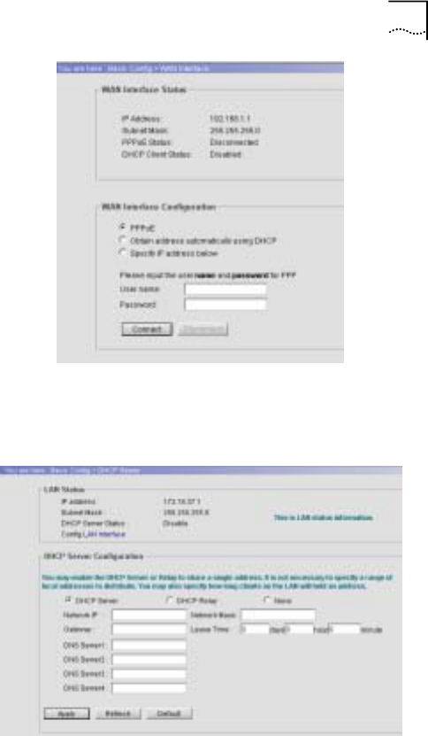
Chapter 8 Web-based Configuration Examples 113
2. Click “Basic Config/DHCP server” to display the “DHCP
Server” window. Enable the DHCP server for the LAN
interface.
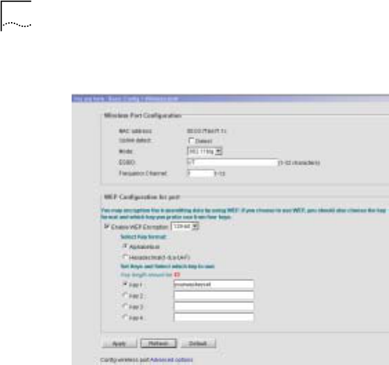
114 Chapter 8 Web-based Configuration Examples
3. Click “Basic Config/Wireless port” to display the
“Wireless Port” window. Configure WEP Encryption.
4. Click “Advanced Config/Isolation&Filter” to display the
“Isolation and Filter” window. Enable user based load
balance.
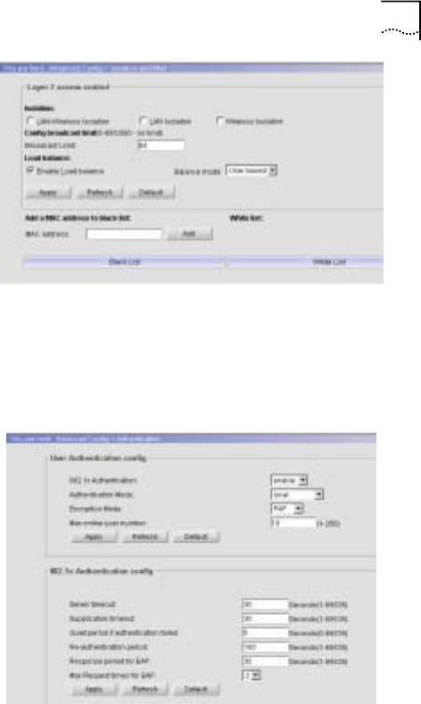
Chapter 8 Web-based Configuration Examples 115
5. Configure 802.1x authentication. Click “Advanced
Config/Authentication” to display the “Authentication”
window. Enable 802.1x authentication, set the
authentication mode to “local” and the maximum
number of online users to “10”.

9 CLI Command Set
The version is 2.0.
EXEC Commands
Debug
This command is used for field debug support and can be
performed only by an administrator.
Syntax: debug
Access level: 10
Explanation: Use this command to reach the debug level.
Enable
Use this command to reach the privileged EXEC level.
Syntax: enable
Access level: 1
9

118 Chapter 9 CLI Command Set
Clear
Use this command to clear the screen. It can be used at any
configuration level.
Syntax: clear
Access level: 0
End
Use this command to return to the privileged EXEC mode from
any CLI level except EXEC level. This command can be used at
any configuration level except EXEC level.
Syntax: end
Access level: 0
Exit
Use this command to return one level back. Use “exit all” to
return to EXEC level. This command can be used at any
configuration level.
Syntax: exit [all]
Access level: 0

Chapter 9 CLI Command Set 119
History
Use this command to show the history substitution buffer
contents. This command can be used at any configuration level.
Syntax: history
Access level: 0
Explanation: Use this command to show the command history
contents.
Logout
Use this command to terminate a terminal session. It can be
used at any configuration level.
Syntax: logout
Access level: 0
Ping
Use this command to test the network layer connectivity
between source and destination address. This command can be
used at any configuration level.
Syntax: ping <ip-address>
Access level: 2

120 Chapter 9 CLI Command Set
Quit
Use this command to return to the EXEC mode from any CLI
level. This command can be used at any configuration level.
Syntax: quit
Access level: 0
Show
The show commands are described in Section 6.
Tree
Use this command to show the command tree. It can be used at
any configuration level.
Syntax: tree
Access level: 0
Write Memory
Use this command to save the running configuration into the
configuration file. This command can be used at any
configuration level.
Syntax: write memory

Chapter 9 CLI Command Set 121
Access level: 2
Explanation: Use this command to save the running
configuration into the startup-config file.
Privileged EXEC Commands
Configure
Use this command to reach the global CONFIG level.
Syntax: configure {terminal}
Access level: 1
Copy Config to TFTP
Use this command to upload a copy of the configuration file to
the designated TFTP server.
Syntax: copy config to tftp <ip-address> <filename>
Possible value: ip-address: IP address of the TFTP server
filename: Up to 32 characters for the designated file name on
the TFTP server
Access level: 2

122 Chapter 9 CLI Command Set
Copy Config from TFTP
Use this command to download a copy of the configuration file
from the designated TFTP server.
Syntax: copy config from tftp <ip-address> <filename>
Possible value: ip-address: IP address of the TFTP server
filename: Up to 32 characters for the designated file name on
the TFTP server
Access level: 2
Copy Image From TFTP
Use this command to download a copy of the software image
from TFTP server. Reload (reboot) the system to activate the
newly downloaded image.
Syntax: copy image from tftp <ip-address> <filename>
Possible value: ip-address: IP address of the TFTP server
filename: Up to 32 characters for the designated file name on
the TFTP server
Access level: 2

Chapter 9 CLI Command Set 123
Copy Image to TFTP
Use this command to download a copy of the software image to
the TFTP server.
Syntax: copy image from tftp <ip-address> <filename>
Possible value: ip-address: IP address of the TFTP server
filename: Up to 32 characters for the designated file name on
the TFTP server
Access level: 2
Disable
Use this command to return to the EXEC command level from
the Privileged EXEC level
Syntax: disable
Access level: 0
Erase Config
Use this command to erase the config file stored in the flash.
Syntax: erase config
Access level: 2

124 Chapter 9 CLI Command Set
Clear ARP
Use this command to reset the ARP table.
Syntax: clear arp
Access level: 2
Explanation: Use this command to clear the ARP table or
delete all dynamic entries.
Clear DHCP Binding
Use this command to delete one or all automatic address
binding(s) from the Dynamic Host Configuration Protocol
(DHCP) Server database.
Syntax: clear dhcp binding [ip-address]
Possible value: ip-address: The address of the binding to be
cleared
Default value: clear all bindings
Access level: 2
Explanation: Use this command to clear DHCP server IP
address bind table.

Chapter 9 CLI Command Set 125
Clear DHCP Statistics
Use this command to reset all Dynamic Host Configuration
Protocol (DHCP) Server counters or Relay counters.
Syntax: clear dhcp statistics [relay | server]
Default value: Relay and server’s statistics
Access level: 2
Clear Dot1x Statistics
Use this command to reset all 802.1x counters.
Syntax: clear dot1x statistics
Access level: 2
Explanation: Use this command to clear DOT1X statistics.
Clear RADIUS
Use this command to reset all radius counters.
Syntax: clear radius
Access level: 2

126 Chapter 9 CLI Command Set
Explanation: Use this command to clear RADIUS client
statistics.
Clear MAC
Use this command to reset the MAC table.
Syntax: clear mac
Access level: 2
Clear NAT
Use this command to clear all NAT entries.
Syntax: clear nat
Access level: 2
Clear NAT Translation
Use this command to clear NAT translation entries.
Syntax: clear nat
Access level: 2
Kill
Use this command to terminate a CLI session.

Chapter 9 CLI Command Set 127
Syntax: kill <session-id>
Possible value: session-id: 0 - 4
Access level: 2
Reboot
Use this command to reboot the system.
Syntax: reboot
Access level: 2
Auto-config Enable/Disable
Use this command to enable or disable auto configuration.
Syntax: auto-config enable/disable
Access level: 2
Global Config Commands
AP-Mode
Use this command to select AP work mode.
Syntax: ap-mode {bridge|route}

128 Chapter 9 CLI Command Set
Access level: 2
ARP Entry
Use this command to add/delete an ARP entry.
Syntax: arp entry <ip-address> <mac-address>
no arp <ip-address>
Possible value: mac-address: MAC address, format:
xx:xx:xx:xx:xx:xx
Access level: 2
Broadcast Limit
Use this command to enable broadcast limit and set limit
packets value per second
Syntax: broadcast limit <packets>
no broadcast limit
Possible value: packets: 0-65535; 0 means broadcast limit is
disabled
Default value: 64
Access level: 2

Chapter 9 CLI Command Set 129
Console Baud-Rate
Use this command to set the baud rate of the console interface.
After the configuration is changed, the connection to the current
console-interface user will be lost.
Syntax: console baud-rate <value>
no console baud-rate
Possible value: value: {9600|19200|38400|57600|115200}
Default value: 9600
Access level: 2
Console Timeout
Use this command to set the aging time how long the console
will be logout without any input.
Syntax: console timeout <value>
no console timeout
Possible value: value: 0~240 minutes (0 means to disable
console timeout)
Default value: 30 minutes

130 Chapter 9 CLI Command Set
Access level: 2
Explanation: Use this command to set the console aging time.
DHCP Service
Use the dhcp service global configuration command to select
the DHCP configuration. Use the no form of this command to
disable the DHCP service.
Syntax: dhcp service {server| relay}
no dhcp service
Possible value: Server or relay
Access level: 2
DHCP-Client Enable /Disable
Use this command to enable or disable the DHCP client feature.
Syntax: dhcp-client {enable|disable}
Default value: enable
Access level: 2

Chapter 9 CLI Command Set 131
DHCP-Client Trust
Use this command to set the trusted DHCP server IP addresses.
(Up to 5)
Syntax: [no] dhcp-client trust <ip-address>
Possible value: ip-address: IP address of DHCP server
Access level: 2
DHCP-Pool
Use the dhcp-pool global configuration command to configure
Dynamic Host Configuration Protocol (DHCP) address pool on
the DHCP Server and enter the domain’s DHCP pool
configuration mode. Use the no form of this command to
remove the address pool.
Syntax: [no] dhcp-pool
Default value: DHCP address pools are not configured.
Access level: 2
DHCP-Server Host
Use this command to set the DHCP server’s IP address when
DHCP relay is enabled; use the no form to delete the server.

132 Chapter 9 CLI Command Set
Syntax: [no]dhcp-server host <IPaddress> (Up to 3)
Possible value: ip address
Access level: 2
Dot1x Authentication Enable / Disable
Use this command to enable or disable the DOT1X
authentication function.
Syntax: dot1x authentication {enable|disable} <port>
Possible value: Port: lan, wlan1, wlan2
Default value: disable
Access level: 2
Dot1x Authentication Mode
Use this command to set the authentication mode for this AP.
Syntax: dot1x authentication mode <port> <mode>
no dot1x authentication mode <port>
Possible value:
Port: lan, wlan1, wlan2

Chapter 9 CLI Command Set 133
Mode: local, remote, local-remote, remote-local
Default value: local-remote
Access level: 2
Dot1x Encryption-Mode
Use this command to set the authentication encryption mode for
each port.
Syntax: dot1x encryption-mode <port> {chap|pap}
no dot1x encryption-mode <port>
Possible value:
Port: lan, wlan1, wlan2
chap|pap: keyword
default value: pap
Access level: 2
Dot1x Initialize
Use this command to initialize an 802.1x’s user based on the
user ID.
Syntax: dot1x initialize <userid>

134 Chapter 9 CLI Command Set
Possible value: <userid>: 1-256
Access level: 2
Explanation: Use this command to initialize the DOT1X
subscriber status.
Dot1x Max-Req
Use this command to set the maximum number of times that the
device sends an Extensible Authentication Protocol (EAP) –
(request /identity frame (no response is received)) before
restarting the authentication process. Use the no form of this
command to return to the default setting.
Syntax: dot1x max-req <count>
no dot1x max-req
Possible value: count: 1 - 2.
Default value: 2 times
Access level: 2
Dot1x Quiet-Period
Use this command to set the number of seconds that the switch
remains in the quiet state following a failed authentication

Chapter 9 CLI Command Set 135
exchange (for example, the client provided an invalid password).
Use the no form of this command to return to the default setting.
During the quiet period, the switch does not accept or initiate
any authentication requests. The user should change only the
default value of this command to adjust for unusual
circumstances such as unreliable links or specific behavioral
problems with certain clients and authentication servers. To
provide a faster response time to the user, enter a smaller
number than the default.
Syntax: dot1x quiet-period <seconds>
no dot1x quiet-period
Possible value: seconds: 0-65535s
Default value: 5s
Access level: 2
Explanation: Use this command to set another authentication
beginning period after a failed authentication exchange.
Dot1x Re-Authenticate
Use this command to manually initiate a re-authentication of all
802.1X-enabled ports or the specified 802.1X-enabled port. The
user can use this command to re-authenticate a subscriber
without waiting for the configured number of seconds between

136 Chapter 9 CLI Command Set
re-authentication attempts (re-authperiod) and automatic re-
authentication.
Syntax: dot1x re-authenticate <userid>
Possible value: userid: 1-256
Access level: 2
Explanation: Use this command to manually initiate a re-
authentication for a subscriber at once.
Dot1x Re-Authentication
Use this command to enable periodic re-authentication of the
client. Use the no form of this command to return to the default
setting. Configure the time period between periodic re-
authentication attempts by using the dot1x re-authperiod
command.
Syntax: [no] dot1x re-authentication <userid>
Possible value: userid: 1-256
Default value: Periodic re-authentication is disabled
Access level: 2
Explanation: Use this command to set the periodic re-
authentication status while the subscriber is online.

Chapter 9 CLI Command Set 137
Dot1x Re-Authperiod
Use this command to set the number of seconds between re-
authentication attempts. Use the no form of this command to
return to the default setting. The dot1x re-authperiod
configuration command affects the behavior of the device only if
the user has enabled periodic re-authentication by using the
dot1x re-authentication configuration command. The user
should change the default value of this command only to adjust
for unusual circumstances such as unreliable links or specific
behavioral problems with certain clients or authentication
servers.
Syntax: dot1x re-authperiod <seconds>
no dot1x re-authperiod
Possible value: seconds: 1-65535 s
Default value: 180s
Access level: 2
Explanation: Use this command to set the period between re-
authentication attempts.
Dot1x Server-Timeout
Use this command to set the Back-End Authenticator-to-
Authentication-Server Retransmission Time for Transport Layer

138 Chapter 9 CLI Command Set
Packets. Use the no form of this command to return to the
default setting. The authentication server notifies the back-end
authenticator each time it receives a transport layer packet.
When the back-end authenticator does not receive a notification
after sending a packet, the back-end authenticator waits for
certain time period (i.e. set time period) and then retransmits the
packet.
Syntax: dot1x server-timeout <seconds>
no dot1x server-timeout
Possible value: 1-65535s
Default value: 30s
Access level: 2
Explanation: Use this command to set dot1x server timeout.
Dot1x Supplicant-Timeout
Use this command to set the Back-End Authenticator-to-
Supplicant Retransmission Time for EAP-Request Frames. Use
the no form of this command to return to the default setting. The
supplicant notifies the back-end authenticator that the
authenticator received the EAP-request frame. When the back-
end authenticator does not receive this notification, the back-
end authenticator waits for certain time period (i.e. set time
period) and then retransmits the frame.

Chapter 9 CLI Command Set 139
Syntax: dot1x supplicant-timeout <seconds>
no dot1x supplicant-timeout
Possible value: 1-65535s
Default value: 30s
Access level: 2
Explanation: Use this command to set dot1x supplicant timeout.
Dot1x TX-Period
Use this command to set the number of seconds that the device
waits for a response to an Extensible Authentication Protocol
(EAP)-request /identity frame from the client before
retransmitting the request. Use the no form of this command to
return to the default setting. The user should change the default
value of this command only to adjust for unusual circumstances
such as unreliable links or specific behavioral problems with
certain clients or authentication servers.
Syntax: dot1x tx-period <seconds>
no dot1x tx-period
Possible value: <seconds>: 1-65535 s
Default value: 30s

140 Chapter 9 CLI Command Set
Access level: 2
Explanation: Use this command to set dot1x tx-period.
Dynamic-User
Add or delete a dynamic user for local authentication
Syntax: dynamic-user {name <username>} {password
<passwd>}
no dynamic-user {name <username> }
Possible value: name: no longer than 32 characters; passwd:
no longer than 32 characters
Access level: 2
Explanation: Use this command to create/delete a local
authentication user in the database.
Dynamic-User Enable / Disable
Use this command to enable/disable a dynamic user account.
Syntax: dynamic-user {name <username>} {enable| disable}
Access level: 2

Chapter 9 CLI Command Set 141
Explanation: Use this command to enable/disable an account
in the database
Ethernet-Port
Use this command to enter the Ethernet port configuration level.
Syntax: ethernet-port <ports>
Possible value: ports: wan, lan1 lan2 lan3 lan4
Access level: 1
Hostname
Use this command to set the host name of the current system
for prompting.
Syntax: hostname <string>
Possible value: Up to 32 alphanumeric, ‘-’, and ‘_’ characters
for the hostname text string
Access level: 2
IAPP
Use this command to enter IAPP mode.
Syntax: iapp

142 Chapter 9 CLI Command Set
Access level: 2
Interface
Use this command to access the interface CONFIG level of the
CLI.
Syntax: interface ethernet {lan | wan}
Possible value: lan: Enters the LAN interface,
wan: Enters the WAN interface.
Access level: 2
IP Default-Route
Use the ip default-route global configuration command to
define a default gateway (router) when IP routing is disabled.
Syntax: ip default-route <ip-address>
no ip default-route
Possible value: ip-address: IP address of the router.
Default value: Disabled.
Access level: 2

Chapter 9 CLI Command Set 143
Explanation: Use this command to set the default route for this
AP.
IP RADIUS Source-Interface
To force RADIUS to use the IP address of a specified interface
for all outgoing RADIUS packets, use the ip radius source-
interface global configuration command.
Syntax: ip radius source-interface {wan | lan}
no ip radius source-interface
Access level: 2
Explanation: Use this command to set the RADIUS source
interface.
IP Route
Use the ip route command in Global configuration command
mode to establish static routes.
Syntax: ip route <ipaddr> <mask> <next-hop>
no ip route <ipaddr> <mask>
Possible Value:

144 Chapter 9 CLI Command Set
ipaddr: This parameter identifies the destination IP address of
the static route.
mask: This parameter identifies the destination prefix mask of
the static route.
next-hop: This parameter identifies the IP address of the next
hop that can be used to reach the network.
Access level: 2
Isolation
Use this command to set isolation between the subscribers. No
parameter means to isolate all.
Syntax: isolation [lan | lan-wlan | wlan ]
Access level: 2
Load-Balance Enable/Disable
Use this command to enable or disable the load balance.
Syntax: load-balance {enable|disable}
Access level: 2

Chapter 9 CLI Command Set 145
Load-Balance Mode
Use this command to set load-balance mode.
Syntax: load-balance mode {user-base | flux-base}
Default Value: user-base
Access level: 2
MAC Age Time
Use this command to set the aging period for all MAC address
entries in the address table of the switch.
Syntax: mac age time <value>
Possible value: value: 10~65535 seconds
Default value: 300 seconds
Access level: 2
MAC Black-List
Use this command to add/delete a MAC black list entry. The
packets from the source MAC addresses will not be permitted to
access the AP.
Syntax: [no] mac black-list <mac-address>

146 Chapter 9 CLI Command Set
Access level: 2
Max-Online-User
Use this command to set the maximum number of online users
this AP permits.
Syntax: max-online-user <port> <count>
no max-online-user <port>
Possible value:
Port: lan,wlan1,wlan2
Count: 1-256
Default value: count: 256
Access level: 2
NAT Enable/Disable
Use this command to enable or disable NAT.
Syntax: nat {enable|disable}
Default value: Enabled
Access level: 2

Chapter 9 CLI Command Set 147
NAT Interface
Use this command to specify the interface attached to NAT.
Syntax: nat interface {inside | outside} <lan | wan>
Default value:
inside: lan(downlink)
outside: wan (uplink)
Access level: 2
NAT Map
Use this command to configure static entries of address
mapping for basic NAT.
Syntax: [no] nat map <local-ip> <global-ip>
Possible value:
local-ip: Private IP address inside NAT .
global-ip: Global IP address outside NAT.
Access level: 2

148 Chapter 9 CLI Command Set
NAT Mode
Use this command to set NAT mode.
Syntax: nat mode {napt|basic}
Default value: napt
Access level:2
NAT Pool
Use this command to configure address pool for dynamic NAT.
Syntax: [no] nat pool <start-ip> <ip-mask>
Possible value:
start-ip: Specifies the IP address at the beginning of the pool
range.
ip-mask: Specifies the network mask associated with the
address pool.
Access level: 2
NAT Redirect
Use this command to configure static entry of host redirection
for NAPT.

Chapter 9 CLI Command Set 149
Syntax: [no] nat redirect <global-port> <local-ip>
Possible value:
global_port: Destination port number of incoming packets.
local_ip: Private IP address to be redirected.
Access level: 2
NAT Timeout
Use this command to set the age timeout for all NAT entries.
Syntax: nat timeout <secs>
Possible value:
secs: 1-3600
Default value: 120
Access level: 2
Operator Access level
Use this command to change the user’s access level.
Syntax: operator access level {name <user-name>} {level
<access-level>}

150 Chapter 9 CLI Command Set
Possible value: user-name: Up to 16 alphanumeric characters
for the user name
access-level:
10 – Administrator
2 – Power configuration access
1 – Port-configuration access
0 – Read-only access
Access level: 10
Operator Add / Delete
Use this command to add/delete a user account.
Syntax: operator add {name <user-name>} {level <access-
level>} {mode <access-mode>}
operator delete {name < name>}
Possible value: user-name: Up to 16 alphanumeric characters
for the user name
access-level:
10 – Administrator

Chapter 9 CLI Command Set 151
2 – Power configuration access
1 – Port configuration access
0 – Read only access
access-mode: Telnet, console or web. Multiple values can be
input.
Access level: 10
Note: When the operator <user-name> {level <access-level>} {mode
<access-mode>} command is entered, the system displays
“Enter new password: ” and “Confirm new password: ” in
next line, the user should input the correct password.
Operator Password
Use this command to change the user’s password whose name
is <username>.
Syntax: operator password <user-name>
Possible value: user-name: Up to 16 alphanumeric characters
for the user name
Access level: 1
Note: When the command “user password <user-name>” is entered,
the system displays “Enter old password: ” (For system
administrator, this line will not be displayed.), “Enter new

152 Chapter 9 CLI Command Set
password: ” and “Confirm new password: ” in next line, the
user should input the correct password.
PPPoE Auto-Connect Disable/Enable
Use this command to set auto connect to the PPPOE server
when the AP boots successfully.
Syntax: pppoe auto-connect {disable|enable}
Access level: 2
PPPoE Connect
Use this command to connect to the PPPOE server.
Syntax: pppoe connect
Access level: 2
PPPoE Disconnect
Use this command to disconnect from the PPPOE server.
Syntax: pppoe disconnect
Access level: 2
PPPoE User
Use this command to add a PPPoE user.

Chapter 9 CLI Command Set 153
Syntax: pppoe user {name <name>} {password <pwd>}
Possible value: name: up to 30 characters; pwd: up to 30
characters.
Access level: 2
RADIUS-Acctserver {Enable | Disable}
Use this command to enable/disable a designated accounting
server.
Syntax: radius-acctserver {enable | disable} [first | second |
third]
Access level: 2
RADIUS-Acctserver Host
Use the radius-acctserver host global configuration command
to specify a RADIUS accounting server host.
Syntax: radius-acctserver host {first | second | third} <ip-
address>
no radius-acctserver host {first | second | third}
Possible Value: ip-address: IP address of the RADIUS
accounting server host.

154 Chapter 9 CLI Command Set
Access level: 2
RADIUS-Acctserver Info
Use this command to set the designated accounting server’s
parameter(s). Use the no form of this command to set the
designated accounting server’s parameter(s) as default value(s).
Syntax: radius-acctserver info {first | second | third} [acct-
port <port-number>] [accounting-key {string}] [timeout
<seconds >] [dead-time <minutes>] [retransmit <retries >]
no radius-acctserver info {first | second | third} [acct-port]
[accounting-key] [timeout] [dead-time] [retransmit]
Possible Value:
acct-port: 1-65535; default value: 1813
accounting-key {string}: string, default value: “”
timeout: 1-16 seconds; default value: 5 seconds
dead-time: 1-1440 minutes; default value: 5 minutes
retransmit: 1-6; default value: 3
Access level: 2

Chapter 9 CLI Command Set 155
RADIUS-Authserver {Enable | Disable}
Use this command to enable/disable the designated
authentication server.
Syntax: radius-authserver {enable | disable} [first | second |
third]
Access level: 2
RADIUS-Authserver Extra
Use this command to set authentication radius server’s
additional attribute.
Syntax: radius-authserver extra {first | second | third}
[iapp|wpa]
Possible value: iapp|wpa: keywords
Access level: 2
RADIUS-Authserver Host
Use the radius-authserver host global configuration command
to specify a RADIUS authentication server host. The other
parameters are default.
Syntax: radius-authserver host {first | second | third} <ip-
address>

156 Chapter 9 CLI Command Set
no radius-authserver host {first | second | third}
Possible Value: ip-address: IP address of the RADIUS
authentication server host.
Access level: 2
RADIUS-Authserver Info
Use this command to set the designated authentication server’s
parameter(s). Use the no form of this command to set the
designated authentication server’s parameter(s) as default
value(s).
Syntax: radius-authserver info {first | second | third} [auth-
port <port-number>] [authentication-key <string>] [timeout
<seconds >] [dead-time <minutes>] [retransmit <retries >]
no radius-authserver info {first | second | third} [auth-port]
[authentication-key] [timeout] [dead-time] [retransmit]
Possible Value:
auth-port: 1-65535; default value: 1812
authentication-key <string>:string; default value: “”
timeout: 1-16 seconds; default value: 5 seconds
dead-time: 1-1440 minutes; default value: 5 minutes

Chapter 9 CLI Command Set 157
retransmit: 1-6; default value: 3
Access level: 2
RADIUS-Server Dead-Time
To improve RADIUS response time when some servers might
be unavailable, use the radius-server dead-time global
configuration command to cause the unavailable servers to be
skipped immediately. Use the no form to set the dead time to 5
minutes.
Syntax: radius-server dead-time <minutes>
no radius-server dead-time
Possible value: minutes: 1-1440 minutes (24 hours).
Default value: 5.
Access level: 2
RADIUS-Server Retransmit
Use this command to specify the number of times the RADIUS
server sets to down. Use the no form to return to the default
value.
Syntax: radius-server retransmit <retries >

158 Chapter 9 CLI Command Set
no radius-server retransmit
Possible Value: retries: 1-6
Default Value: 3 times
Access level: 2
RADIUS-Server Timeout
Use this command to set the interval a router waits for a server
host to reply. Use the no form to restore the default value.
Syntax: radius-server timeout <seconds >
no radius-server timeout
Possible Value: seconds: 1-16
Default: 5 seconds
Access level: 2
SNMP Client
Use this command to set SNMP client IP address.
Syntax: snmp client <ipaddr> [mask]
no snmp client < ip>

Chapter 9 CLI Command Set 159
SNMP Server Community
Use this command to set SNMP server community.
Syntax: snmp server commnunity {ro | rw} <community>
no snmp server commnunity <community>
Possible value: community: up to 64 characters
Default value: ro community: public; rw community: private.
Access level: 2
SNMP Server Contact
Use this command to set SNMP server contact string
Syntax: snmp server contact <contact>
Possible value: any text up to 255 characters
Access level: 2
SNMP Server Enable/Disable
Use this command to enable or disable SNMP agent.
Syntax: snmp server enable

160 Chapter 9 CLI Command Set
Default value: SNMP agent is enabled
Access level: 2
SNMP Server Location
Use this command to set SNMP server location string.
Syntax: snmp server location <location>
Possible value: any text up to 255 characters
Access level: 2
SNMP Server Sysname
Use this command to set SNMP server system name string.
Syntax: snmp server sysname <sysname>
Possible value: Any text up to 255 characters
Access level: 2
SNMP Server Trap Enable/Disable
Use this command to enable or disable SNMP trap.
Syntax: snmp server trap {enable|disable}

Chapter 9 CLI Command Set 161
Possible value: N/A
Default value: trap is enable
Access level: 2
SNMP Server Trap Host
Use this command to set SNMP trap host.
Syntax: snmp server trap host <host-addr> [community
<trap-community>] [port<trap-port>][version<v1|v2>]
no snmp server trap host <host-addr>
Default value: community :public Port:162 Version: v2
Static-MAC-Address
Use this command to define or remove a MAC address in the
static filtering database.
Syntax: [no] static-mac-address <mac-address>
{wan|lan|wlan}
Possible value: mac-address: xx:xx:xx:xx:xx:xx
Access level: 2

162 Chapter 9 CLI Command Set
Static-User
Use this command to add or delete a static user.
Syntax: static-user {mac <mac-addr>}
no static-user {mac <mac-addr>}
Access level: 2
Static-User Enable / Disable
Use this command to enable or disable a static user.
Syntax: static-user {mac <mac-addr>} <[enable]/[disable]
Possible value: mac-addr: xx:xx:xx:xx:xx:xx
Default value: disable
Access level: 2
Telnet Client
Use this command to set which IP address (subnet) can or
cannot access the device via telnet. (UP TO 10)
Syntax: telnet client <ip-address> [netmask]
no telnet client <ip-address> [netmask]

Chapter 9 CLI Command Set 163
Access level: 2
Telnet Server Enable / Disable
Use this command to enable/disable the telnet server.
Syntax: telnet server {enable|disable}
Default value: disable
Access level: 2
Telnet Timeout
Use this command to set the aging time how long the Telnet will
be logout without any user input.
Syntax: telnet timeout <value>
no telnet timeout
Possible value: value: 0~240 minutes (0 means to disable
timeout)
Default value: value: 6 minutes
Access level: 2
Explanation: Use this command to set telnet aging time

164 Chapter 9 CLI Command Set
User-Force-Offline
Use this command to force the subscriber to be off-line.
Syntax: user-force-offline <userid>
Possible value: userid:1-256
Access level: 2
VLAN Default VID
Use this command to set default VLAN VID. The command will
be valid if the VLAN module is available.
Syntax: vlan default-vid <vid>
no vlan default-vid
Possible value:
vid: 1-4094
Default value: 1
Access level: 2
VLAN Employee Default VID
Use this command to set default VLAN employee VID.

Chapter 9 CLI Command Set 165
Syntax: vlan employee default-vid <vid>
no vlan employee default-vid
Possible value:
vid: 1-4094
Default value: 1
Access level: 2
VLAN Enable/Disable
Use this command to enable or disable VLAN. The command
will be valid if the VLAN module is available.
Syntax: vlan {enable|disable}
Access level: 2
Explanation: Use this command to enable or disable VLAN
VLAN Mode
Use this command to set VLAN work mode.
Syntax: vlan mode {user-based|port-based|mix}
no vlan mode

166 Chapter 9 CLI Command Set
Default value: user-based
Access level: 2
VLAN port-vid
Use this command to set the designated port’s vid.
Syntax: vlan port-vid {lan|wlan1|wlan2} <vid>
no vlan port-vid {lan|wlan1|wlan2}
Possible values:
Vid range:1-4094
Default value:1
Access level: 2
Explanation: Use this command to set the vid of designated
port when work on port-based mode.
VLAN Tag Disable
Use this command to disable VLAN tag. The command will be
valid if the VLAN module is available.
Syntax: vlan tag disable
Access level: 2

Chapter 9 CLI Command Set 167
VLAN Tag Enable
Use this command to enable VLAN tag. The command will be
valid if the VLAN module is available.
Syntax: vlan tag enable
Access level: 2
VLAN Visitor Default Vid
Use this command to set default VLAN visitor VID. The
command will be valid if the VLAN module is available.
Syntax: vlan visitor default-vid <vid>
No vlan visitor default-vid
Possible value:
vid: 1-4094
Default value:1
Access level: 2
Webserver
Use this command to enter webserver config mode

168 Chapter 9 CLI Command Set
Syntax: webserver
Access level: 2
Wireless-Port
Use this command to enter the wireless card configuration level.
Syntax: wireless-port <port>
Possible value: ports: 1-2
Access level: 1
DHCP-pool Configuration Mode
DNS-Server
Use the dns-server DHCP pool configuration command to
specify the Domain Name System (DNS) IP servers available to
a Dynamic Host Configuration Protocol (DHCP) client. To
remove the DNS server list, use the no form of this command.
Syntax: dns-server <address> [address2]
[address3].[address4]
no dns-server

Chapter 9 CLI Command Set 169
Possible value: address: Specifies the IP address of a DNS
server. One IP address is required. The user can specify up to
four addresses in one command line.
address2...address4: (Optional) Specifies up to four addresses
in the command line
Default value: If DNS IP servers are not configured for a DHCP
client, the client cannot correlate host names to the IP
addresses.
Access level : 2
Explanation: Use this command to set/remove DNS server(s).
Excluded-Address
Use the excluded-address global configuration command to
specify IP addresses that a DHCP Server should not assign to
DHCP clients. To remove the excluded IP addresses, use the
no form of this command. (Up to 8)
Syntax: excluded-address <low-address> [high-address]
no excluded-address <low-address> [high-address]
Possible value: low-address: The excluded IP address or first
IP address in the excluded address range.

170 Chapter 9 CLI Command Set
high-address: (Optional) The last IP address in the excluded
address range
Default value: All IP pool addresses are assignable..
Access level : 2
Explanation: Use this command to exclude or remove the
excluded IP address from the pool.
Gateway
Use the gateway DHCP pool configuration command to specify
the default gateway for a Dynamic Host Configuration Protocol
(DHCP) client. To remove the default gateway, use the no form
of this command.
Syntax: gateway <address>
no gateway
Possible value: address: Specifies the IP address of the
gateway
Access level: 2
Explanation: Use this command to set/remove the gateway

Chapter 9 CLI Command Set 171
Lease
Use the lease DHCP pool configuration command to configure
the duration of the lease for an IP address that is assigned by a
Dynamic Host Configuration Protocol (DHCP) Server to a
DHCP client. To restore the default value, use the no form of
this command.
Syntax: lease {[[days <days>] [hours <hours>] [minutes
<minutes>] ] | [ infinite]}
no lease
Possible value: days: Specifies the duration of the lease in
numbers of days
hours: Specifies the number of hours in the lease. A day’s value
must be fed before configuring an hour’s value.
minutes: Specifies the number of minutes in the lease. A day’s
value and an hour’s value must be fed before configuring a
minute’s value.
Infinite: Specifies that the duration of the lease is unlimited
Default value: One day
Access level: 2

172 Chapter 9 CLI Command Set
Explanation: Use this command to set lease for an IP address
that is assigned from the DHCP server.
Network
Use the network DHCP pool configuration command to
configure the subnet number and mask for a Dynamic Host
Configuration Protocol (DHCP) address pool on a DHCP Server.
To remove the subnet number and mask, use the no form of
this command.
Syntax: [no] network <network-number> <mask >
Possible value: network-number: The IP address of the DHCP
address pool
mask: The bit combination that renders which portion of the
address of the DHCP address pool referring to the network or
subnet and which part referring to the host.
Access level: 2
Explanation: Use this command to set/remove the network for
DHCP pool on a DHCP server.
Manual-Binding
Use this command to specify the IP address to a specific MAC
address for a manual binding to a Dynamic Host Configuration
Protocol (DHCP) client.

Chapter 9 CLI Command Set 173
Syntax: manual-binding <ip-addr> <mac-add>
no manual-binding <ip-addr>
Access level: 2
Explanation: Use this command to bind an IP address to a
MAC address.
Ethernet Port configuration level
Speed-duplex
Use this command to modify the speed and duplex mode for the
port.
Syntax: speed-duplex {auto | 10-full | 10-half | 100-full | 100-
half}
Default value: auto
Access level: 2
Interface Mode Commands
Disable
Use this command to disable an interface.
Syntax: disable

174 Chapter 9 CLI Command Set
Access level: 2
Enable
Used this command to enable an interface.
Syntax: enable
Access level: 2
IP Address
Use the ip address command in the interface configuration
command mode to assign/remove an IP address for an
interface on a router.
Syntax: ip address <ipaddress> <netmask>
no ip address
Access level: 2
Wireless Port Configuration Level
Beacon Interval
Use this command to set the beacon interval based on 802.11
Syntax: beacon interval < time>

Chapter 9 CLI Command Set 175
no beacon interval
Possible value: times: 20-1000
Default value: 100
Access level: 2
Explanation: Use this command to set wireless card beacon
frame send interval
Basic Rate
Use this command to set the transmission rate of this wireless
card
Syntax: basic rate < 2 | 11|12|g >
Possible value:
value: 2: 1,2Mbit/s at b mode or b/g mode
11: 1,2,5.5,11Mbit/s at b mode or b/g mode
12: 6, 9,12. at g mode
g: 1,2,5,5,11,6,9,12Mbit/s at b/g mode
Access level: 2

176 Chapter 9 CLI Command Set
Fragment Threshold
Use this command to set the fragment threshold. If the TX
MSDU’s length is larger than the threshold, the mechanism is
enabled.
Syntax: fragment threshold < value>
Possible value: value: 256-2346
Default value: 2346
Access level: 2
Frequency-Channel
Use this command to set the work frequency channel based on
802.11
Syntax: frequency-channel < number>
Possible value: number: 1-13
Default value: 1
Access level: 2

Chapter 9 CLI Command Set 177
DTIM Interval
Use this command to set the DTIM (Delivery Traffic Indication
Message) interval based on 802.11
Syntax: dtim interval < number>
Possible value: number: 1-255
Default value: 2
Access level: 2
Power
Use this command to set the transmit power of the wireless
card
Syntax: power < value>
Possible value: value: 100mw, 50mw, 25mw, 10mw
Access level: 2
Explanation: Use this command to set the transmit power of
the card

178 Chapter 9 CLI Command Set
RTS-CTS Threshold
Use this command to set RTS/CTS threshold. If the TX MPDU’s
length is larger than the threshold, the mechanism is enabled.
Syntax: rts-cts threshold < value>
Possible value: value: 0-2347
Default value: 2347
Access level: 2
SSID
Use this command to set the network name of the wireless card.
SSID (Service Set Identifier)
Syntax: ssid < string>
Possible value: string length: 1-32, such as 0-9, a-z, A-Z,
Access level: 2
Explanation: Use this command to set the hostname for this
card

Chapter 9 CLI Command Set 179
Tx Rate
Use this command to set TX rate used for AP to send unicast
frame. Auto means the AP will auto-select the TX Rate
according to self algorithm.
Syntax: tx rate < value>
Possible value:
value: 1, 2, 5.5, 11, 6,9,12,18,24,36,48,54M, auto
Default value: auto
Access level: 2
Explanation: Use this command to set TX rate
Wireless Mode
Use this command to set wireless card work mode: 11b, 11g,
108g or 11b/g
Syntax: wireless mode < value>
Possible value: value: 11b, 11g, 11b/g, 108g
Default value: 11b/g
Access level: 2

180 Chapter 9 CLI Command Set
Explanation: Use this command to set wireless mode.
WDS-Mode Enable / Disable
Use this command to set the wireless card work mode: either
AP or WDS. When it is enabled, the wireless card supports
WDS mode
Use this command to set repeater work mode, either PTP or
PTMP. When it is enabled, the wireless card supports PTMP
mode and enables the WDS mode.
Syntax: wds-mode {<enable | disable> | <PTP|PTMP>}
Default value: disable
Access level: 2
Explanation: Use this command to enable/disable WDS mode
on this card.
WDS Peer MAC
Use this command to set toward AP MAC addresses based on
WDS mode, when PTMP is enabled, input 1-6 MAC addresses
for this wireless card
Syntax: wds peer mac <mac-address> [<mac-address> <mac-
address> <mac-address> <mac-address> <mac-address>]

Chapter 9 CLI Command Set 181
no wds peer mac <mac-address> [<mac-address> <mac-
address> <mac-address> <mac-address> <mac-address>]
Access level: 2
Explanation: Use this command to set toward AP MAC
address on this card.
WEP Encryption Enable / Disable
Use this command to enable WEP encryption.
Syntax: wep encryption <enable|disable>
Default value: disable
Access level: 2
WEP Encryption Key
Use this command to set the first WEP key.
Syntax wep encryption key key1 <string> key2 <string>
key3<string> key4<string>
no wep encryption key [key1] [key2] [key3] [key3]
Possible value: string length: 26
Access level: 2

182 Chapter 9 CLI Command Set
Default WEP-Key
Use this command to set the default WEP key based on 802.11.
Syntax: default wep-key < number>
Possible value: number: 1-4
Default value: 1
Access level: 2
Explanation: Use this command to set wireless WEP key for
this card
WEP-Key-Format
Use this command to set WEP key format.
Syntax: wep-key-format < hex | ascii >
Possible value: string: hex or ascii
Access level: 2
WEP-Key-Length
Use this command to set WEP key length.
Syntax: wep-key-length <string>

Chapter 9 CLI Command Set 183
Possible value: string: 64 or 128
Default value: 64
Access level: 2
Antenna
Use this command to select antenna.
Syntax: antenna {ant-a | ant-b | both}
Default value: both
Access level: 2
WPA Mode
Use this command to set WPA authentication mode.
Syntax: wpa auth-mode {wpa|wpapsk|disable}
Possible value: wpa|wpapsk|disable: keywords
Default value: disable
Access level: 2

184 Chapter 9 CLI Command Set
WPA Encryp-Mode
Use this command to set WPA encryption mode.
Syntax: wpa encryp-mode {aes|tkip|auto }
Possible value: aes|tkip|auto :keywords
Default value: auto
Access level: 2
WPA Psk-Passphrase
Use this command to set WPA pre-shared key.
Syntax: wpa psk-passphrase <string>
Possible value: string: Alphanumeric, length range: 8-63
Access level: 2
WPA Groupkey-Update-Interval
Use this command to set WPA group key update interval.
Syntax: wpa groupkey-update-interval <value>
no wpa groupkey-update-interval

Chapter 9 CLI Command Set 185
Possible value: value range:0(means no update), 30- 65535
seconds
Default value: 1800 seconds
Access level: 2
Optimize-108g Enable/Disable
Use this command to enable or disable 108g optimization.
Syntax:optimize-108g enable/disable
Access level: 2
Webserver Mode
Enable/Disable
Use this command to enable or disable the web server.
Syntax: enable/disable
Access level: 2
Explanation: Use this command to enable or disable the web
server.

186 Chapter 9 CLI Command Set
IP-Filter Enable/Disable
Use this command to enable or disable the web server’s IP-filter.
Syntax: ip-filter enable/disable
Access level: 2
Explanation: Use this command to enable or disable the web
server’s IP-filter.
IP-Filter Client
Use this command to set IP-filter’s IP address.
Syntax: ip-filter client <ip> [mask]
no ip-filter client <ip>
Access level: 2
Explanation: Use this command to add or remove the ipfilter’s
IP address
Port-Filter
Use this command to enable or disable the web server’s port
filter.
Syntax: port-filter {enable|disable} <port>

Chapter 9 CLI Command Set 187
Possible value:
port: wan,lan,wlan
Access level: 2
IAPP Mode
Enable/Disable
Use this command to enable or disable IAPP.
Syntax: enable/disable
Access level: 2
ESP Enable/Disable
Use this command to enable or disable ESP.
Syntax: esp enable/disable
Access level: 2
Mode
Use this command to set IAPP mode.
Syntax: mode {local|remote}

188 Chapter 9 CLI Command Set
no mode
Possible value: local|remote: keywords
Default value: remote
Access level: 2
Map
Use this command to set IAPP map entry.
Syntax: map <mac> <ip> (max 64 entries)
no map <mac>
Access level: 2
Explanation: Use this command to add or delete IAPP map
entry.
Secret
Use this command to set IAPP secret.
Syntax: secret <string>
Possible value: string: alphanumeric; max length:16
Access level: 2

Chapter 9 CLI Command Set 189
Debug Mode
Ping
Use this command to test the network layer connectivity
between source and destination address. This command is a
global command and can be used at any configuration level.
Syntax: ping <ip-address> [times <times>] [packet-size <size>]
Possible value: ip-address: Specifies the network layer
destination address .
Times: Specifies the packets to send. Possible values are 1-
10000.
packets-size: Specifies the data size of ICMP packet. 0-65000.
Access level: 2
Explanation: Use this command to test the network layer
connectivity
Debug-Module
Use this command to enable or disable every module’s debug
message
Syntax: debug-module <module-name> <level>

190 Chapter 9 CLI Command Set
no debug-module [module-name]
Possible value: module name: DOT1X, SMI, RADIUS, DHCPS,
DHCPR, DHCPC, IP, NAT, BRIDGE,DOT11, WEB, CLI, SNMP,
TELETE, L2TP, PPP, PPPOEC
level: ERROR, WAINING, TRACE
Access level: 2
NAT Logging
Use this command to set NAT logging information.
Syntax: nat logging [detail|data]
no nat logging [detail|data]
Possible value: detail|data: keywords
Access level: 2
NAT Print
Use this command to set NAT print information
Syntax: nat print {detail|data|error}
no nat print {detail|data|error}
Possible value: detail|dat|error: keywords

Chapter 9 CLI Command Set 191
Access level: 2
Sys-Function
Use this command to execute some system function.
Syntax: sys-function <function-name>
Possible value:
function-name: i, arpShow, ifShow, inetstatShow, ipstatShow,
netStackDataPoolShow, netStackSysPoolShow, mbufShow,
hostShow, routeShow, routeStatShow, udpstatShow,
tcpstatShow, icmpstatShow, CPUReport
Access level: 2
Show Version
Use this command to display internal version.
Syntax: show version
Access level: 2
Explanation:
Execute the command, and the following will be displayed:
Hardware version: 1.0.0.1

192 Chapter 9 CLI Command Set
Software version: 1.1.1.0
Create date: Feb 9 2004, 13:49:59
Show Memory
Use this command to display the memory information.
Syntax: show memory
Access level: 2
Explanation:
Show NAT Run
Use this command to display NAT running configuration
Syntax: show nat run
Access level: 2
Show Debug_Module
Use this command to display debug module status.
Syntax: show debug_module
Access level: 0

Chapter 9 CLI Command Set 193
Net-Security Rate-Limit Enable/Disable
Use this command to enable/disable the rate limit.
Syntax: rate-limit enable/disable
Possible value: N/A
Access level: 0
Net-Security Syn-Cache Enable/Disable
Use this command to enable/disable SYN cache.
Syntax: syn-cache enable/disable
Access level: 0
Net-Security Attack-Defense Enable/Disable
Use this command to enable/disable the network attack defense.
Syntax: attack-defense enable/disable
Access level: 0
Show Net-Security
Use this command to display network security configuration.

194 Chapter 9 CLI Command Set
Syntax: show net-security
Access level: 0
Explanation:
Execute this command, and the following will be displayed:
Rate Limit Status : Enable
SYN Cache Status : Disable
Network Attack Defense : Disable
Ipstack Debug
Use this command to enable IP stack print packet information.
Syntax: ipstack-debug <module>
no ipstack-debug <module>
Possible value: module: IP, ICMP, TCP, UDP, IGMP
Access level: 0
Show Ipstack-Debug
Use this command to display the IP stack debug status.
Syntax: show ipstack-debug
Access level: 0

Chapter 9 CLI Command Set 195
Explanation:
Execute this command, and the following will be displayed:
IP debug : On
ICMP debug : Off
TCP debug : On
UDP debug : Off
IGMP debug : On
Show
Show ARP
Use this command to display ARP entries.
Syntax: show arp
Access level: 0
Show Console
Use this command to display the console config information,
such as baud-rate, console session time-out and so on.
Syntax: show console
Access level: 0
Explanation:

196 Chapter 9 CLI Command Set
Execute this command, and the following will be displayed:
Baud rate : 9600
Timeout : 30 minutes
Parity : no
Data bits : 8
Stop bits : 1
Flow control : disable
Show DHCP-Client
Use this command to display the DHCP client configuration.
Syntax: show dhcp-client
Access level: 0
Explanation:
Execute this command, and the following will be displayed:
DHCP status : enable
DHCP server :
DHCP trusted server: 1.1.1.1
Show DHCP Service
Use this command to display the current DHCP service (RELAY
or SERVER) in the system.

Chapter 9 CLI Command Set 197
Syntax: show dhcp service
Access level: 0
Show DHCP Binding
Use this command to display address bindings on Dynamic
Host Configuration Protocol (DHCP) server.
Syntax: show dhcp binding [ip-address] | [manual ] | [ auto]
Possible value: ip-address: Specifies the IP address of the
DHCP client for which bindings will be displayed
Manual: Displays only manual binding’s address
Auto: Displays only auto binding’s address
Default value: All address bindings are shown.
Access level: 0
Show DHCP Relay
Use this command to display DHCP relay agent’s configuration
parameters.
Syntax: show dhcp relay
Access level:0

198 Chapter 9 CLI Command Set
Show DHCP Server
Use this command to display DHCP server’s configuration
parameters.
Syntax: show dhcp server
Access level:0
Show DHCP Statistics
Use this command to display Dynamic Host Configuration
Protocol (DHCP) Server statistics.
Syntax: show dhcp statistics [relay |server]
Default value: all statistics
Access level: 0
Show Dot1x Configuration
Use this command to display the PAE capabilities, protocol
version, and other global dot1x parameters such as max-req,
re-authperiod, server-timeout supplicant-timeout and so on.
Syntax: show dot1x
Access level: 0

Chapter 9 CLI Command Set 199
Show Dot1x Statistics
Use this command to display the statistics of 802.1x.
Syntax: show dot1x statistics
Access level : 0
Show Flash
Use this command to list the flash code information, such as
version number, size and so on.
Syntax: show flash
Access level: 0
Explanation:
Execute this command, and the following will be displayed:
/image <DIR> 2000-01-16 21:31:26
/image/3001A.Z 931895 2000-01-02 22:18:26
/config <DIR> 2000-01-16 21:31:26
/config/config 6034 2000-01-09 21:34:08
Show Dot1x Authentication Configuration
Use this command to display the dot1x authentication
configuration.

200 Chapter 9 CLI Command Set
Syntax: show dot1x authentication configuration
Access level: 0
Show MAC
Use this command to display the MAC addresses.
Syntax: show mac [type] [port]
Possible value: type: static | dynamic
Access level: 0
Explanation:
Execute this command, and the following will be displayed:
MAC State Port Pass-time Ageing-Time
-----------------------------------------------
00:06:5b:2c:eb:f8 Dynamic LAN 215 300
00:06:5b:a2:07:f2 Dynamic LAN 264 300
00:08:74:9c:e7:f0 Dynamic LAN 228 300
00:08:74:92:07:ee Dynamic LAN 221 300
00:0b:db:53:77:eb Dynamic LAN 223 300
00:08:74:f1:8f:e5 Dynamic LAN 219 300

Chapter 9 CLI Command Set 201
Show MAC Black-List
Use this command to display the black MAC list.
Syntax: show mac black-list
Access level: 2
Show MAC White-List
Use this command to display the white MAC list.
Syntax: show mac white-list
Access level: 2
Show NAT Translation
Use this command to display the currently active NAT
translations.
Syntax: show nat translation
Access level: 2
Explanation:
Execute this command, and the following will be displayed:
Local ip addr global ip addr local port global port

202 Chapter 9 CLI Command Set
Show NAT Configuration
Use this command to display all NAT configuration information.
Syntax: show nat configuration
Access level: 2
Explanation:
Execute this command, and the following will be displayed:
Eable/disable , timeout value
Nat pool information(<start-ip> <end-ip> <ip-mask>)
Nat map information(<local-ip> <global-ip>)
Nat redirect information(<global-port> <local-port> <local-ip>)
Show Managed-Interface
Use this command to display the IP information of the
management interface.
Syntax: show managed-interface
Access level: 0
Explanation:
Execute this command, and the following will be displayed:

Chapter 9 CLI Command Set 203
MAC address :
IP address :
Subnet mask :
Default gateway : (wan only)
Show IP-Route
Use this command to display the static or all route entries.
Syntax: show ip-route [static]
Access level: 0
Show Access-List Configuration
Use this command to display the access-list configuration.
Syntax: show access-list configuration
Access level: 0
Show Port Config
Use this command to display the configuration information of
one or all ports, such as speed duplex, priority, PVID and so on.
Syntax: show port config
Access level: 0

204 Chapter 9 CLI Command Set
Explanation:
Execute this command, and the following will be displayed:
Port Link State AutoCap SpeedDuplex PVID Pri FlowCtrl
Protected
1 up enable ----- 100-full 1 0 disable
Show RADIUS Configuration
Use this command to show the radius configuration information
summary.
Syntax: show radius configuration
Access level: 0
Show RADIUS Statistics
Use this command to show the statistics of radius client.
Syntax: show radius statistics
Access level: 0
Show Sms User
Use this command to show the local user configuration
information, including: Status, ISP name, Flag, Username,
password, MAC address, IP address, VLAN ID and Port.

Chapter 9 CLI Command Set 205
Syntax: show sms user {name <name> | mac <macaddr> |
{all | dynamic | static}} [parameters]]
Possible value: parameters : [lock<enable/disable>]
Access level : 0
Show SMS Online-User
Use this command to show the online user ‘s information.
Syntax: show sms online-user
Access level : 0
Show Wireless-Port
Use this command to show the wireless port configuration
information.
Syntax: show wireless-port
Access level: 0
Show System
Use this command to display the system information, such as
contact, location, name, up-time, software version, hardware
version and so on.

206 Chapter 9 CLI Command Set
Syntax: show system
Access level: 0
Explanation:
Execute this command, and the following will be displayed:
Serial number : 000008c42671
System uptime : 0 days 21 hours 27 minutes 5
seconds
Console baudrate : 9600
Board temperature : 48.0 (C)
Hardware version : 1.0.0
Software version : 1.0.0
Show Telnet
Use this command to display all the telnet configuration
information, such as the telnet server’s status, telnet mode,
telnet session time-out and so on.
Syntax: show telnet
Access level: 0
Explanation:
Execute this command, and the following will be displayed:

Chapter 9 CLI Command Set 207
Telnet server status : Enable
Telnet session timeout : 30 minute(s)
Show SNMP Server Configuration
Use this command to disable SNMP server configuration,
including trap configuration.
Syntax: show snmp server configuration
Access level: 0
Show AP-Mode
Use this command to display the AP work mode.
Syntax: show ap-mode
Access level: 0
Show Load-Balance Configuration
Use this command to show the load balance configuration.
Syntax: show load-balance configuration
Access level: 0

208 Chapter 9 CLI Command Set
Show Who
Use this command to display the login operator.
Syntax: show who
Access level: 0
Show Running-Config
Use this command to display the running configuration.
Syntax: show running-config
Access level: 0
Show Startup
Use this command to display the startup configuration.
Syntax: show startup
Access level: 0
Show WPA Configuration
Use this command to display the WPA configuration.
Syntax: show wpa configuration

Chapter 9 CLI Command Set 209
Access level: 0
Explanation:
Execute this command, and the following will be displayed:
wpa auth mode : wpa
encryption mode : tkip
gtk update interval : 1800 seconds
wpa-psk passphrase : abcdefg
Show Webserver
Use this command to display the WEB Server configuration.
Syntax: show webserver
Access level: 0
Explanation:
Execute this command, and the following will be displayed:
WEB Status : enable
Show VLAN Configuration
Use this command to display VLAN configuration. This
command will be valid if the VLAN module is available.
Syntax: show vlan configuration

210 Chapter 9 CLI Command Set
Access level: 0
Explanation:
Execute this command, and the following will be displayed:
VLAN Status : enable
VLAN Tag Status : enable
VLAN Default vid : 1
Show VLAN Binding
Use this command to display VLAN binding. This command will
be valid if the VLAN module is available.
Syntax: show vlan binding
Access level: 0
Explanation:
Execute this command, and the following will be displayed:
MAC Vid Name
-----------------------------------------------
00:00:00:00:00:01 123 utstar
00:00:00:00:00:02 5 test

Chapter 9 CLI Command Set 211
Show IAPP Configuration
Use this command to display IAPP configuration.
Syntax: show iapp configuration
Access level: 0
Explanation:
Execute this command, and the following will be displayed:
IAPP config status : enable
IAPP running status : UP
IAPP mode : local
ESP mode : enable
IAPP secret : *********
IAPP map:
MAC IP
----------------------------------------------
00:00:00:00:00:01 172.18.32.5
00:00:00:00:00:02 172.18.32.4

10 Troubleshooting
When the user has trouble using the AP, the starting point to
troubleshoot the problem with the AP is to look at its LED
activity. Table 20 is provided to assist the user in diagnosing
and solving the operational problems.
Table 20 Troubleshooting
PWR AP WLAN LAN LINK Description/Action
Green
LED
stays
on
Green
LED on
Green
LED
blinks
Green
LED
blinks
-
No action is required.
Green
LED
stays
on
On Off Off - No LAN activity.
No action is required.
Off Off Off Off Off
Power problem.
Examine the power
supply cable.
Check the power
supply.
10

214 Chapter 10 Troubleshooting
PWR AP WLAN LAN LINK Description/Action
Off Off Off Off
Hardware failure or AP
freezes. Contact the
product supplier.
Green
LED
blinks - - -
Software failure.
Upgrade the software
via Windows IE or
console (hyper
terminal).
Green
LED
blinks
Green
LED
blinks - -
WLAN initialization
failure.
Examine whether the
wireless equipment has
been installed correctly.
Green
LED
stays
on
Green
LED
blinks - Green
LED
blinks -
Ethernet initialization
failure.
Contact the product
supplier.

11 Technical Specifications
Table 21 WA3001 AP Technical Specifications
Type WA3001
Description 2.4GHz(802.11g) 108Mbps
enterprise class wireless access
node
Standard Compliance
-IEEE 802.11
-IEEE 802.11b
-IEEE 802.11g
-IEEE 802.3
-IEEE 802.11i
-IEEE 802.3af
Ethernet
WAN
Interface
One 10/100Mbps interface
(RJ45)
Ethernet LAN
Interface Four 10/100Mbps interfaces
(RJ45)
Interfaces
Console
Interface One RS-232 Console interface
Auto rate
scaling Super G™: 108Mbps
802.11g: 54, 48, 36, 24, 18, 12,
9, 6Mbps
802.11b: 11, 5.5, 2, 1Mbps
Online
subscribers Max. 256
11

216 Chapter 11 Technical Specifications
Type WA3001
Security 64, 128bits WEP
802.1X (EAP-MD5, EAP-TLS,
PEAP, CHAP, PAP)
WPA (TKIP,AES)
WAPI
MAC address access control
Subscriber isolation
Authentication Supports 802.1x and RADIUS
Client
Supports DHCP Server and
DHCP Client
Supports PPOE transparent
transmission
WDS PtP(Point-to-Point) Bridge
PtMP(Point-to-Multi-point) Bridge
L2 roaming IAPP
NAT Supported
Management Web-based management
Telnet
CLI
SNMP v.2 (MIB II)
Work mode Bridge and Router

Chapter 11 Technical Specifications 217
Type WA3001
Reception
sensitivity -73dBm @ 108Mbps, PER < 8%,
OFDM
-73dBm @ 54Mbps, PER < 8%,
ODFM
-90dBm @ 11Mbps, PER < 8%,
CCK
-92dBm @ 6Mbps, PER < 8%,
OFDM
-95dBm @ 1Mbps, PER < 8%,
DBPSK
Operational
frequency
range
2.4GHz~2.4835GHz ISM Band
Channels
Europe/FCC: 2.412~
2.462GHz(11 channels)
China/Europe/ETSI:
2.412~2.472GHz(13 channels)
Transmit
Power China: Four adjustable levels, the
default is 100mw
FCC/EC (default value):
Mode b: 40mw
Mode g: 26mw / 70mw (Turbo mode)
Local power
supply 12V/1.25A
Remote
power supply Supports Standard 802.3af POE
power supply
Electrical
Parameters
Power
consumption
Transmission: <530mA@ 12V DC
Reception: <400mA@ 12V DC
Physical
Features Dimensions 180mm(L) X140mm (W) X40mm
(H)

218 Chapter 11 Technical Specifications
Type WA3001
Weight 450g
Antenna External, various antennae can
be assembled.
LEDs Power, AP, WLAN, LAN, LINK
Operating
temperature -10℃~ 50℃
Storage
temperature -20℃~ 70℃
Environmental
Humidity
(non-
condensing) 10 ~ 90%
MTBF >30000 hours
Coverage
Indoors: 200m
Outdoors: 500m
Security
certificate
- GB9254 Class B
- FCC part 15 Class B (America)
- CE (Europe)
Compatibility - Wi-Fi WECA compatible
Language Chinese (web-based management)
English

12 Acronyms and Abbreviations
AC Access Controller
AS Authentication Server
BRAS Broadband Remote Access Server
CLI Command Line Interface
DHCP Dynamic Host Configuration Protocol
DTIM Delivery Traffic Indication Message
EAP Extensible Authentication Protocol
ESSID Extended Service Set Identifier
IEEE Institute of Electrical and Electronics Engineering
LAN Local Area Network
MAC Media Access Control
MD5 Message Digest Algorithm 5
12

220 Chapter 12 Acronyms and Abbreviations
MIB Management Information Base
MII Media Independent Interface
MTU Maximum Transmission Unit
NAS Network Access Server
NAPT Network Address Port Translation
NAT Network Address Translation
NMS Network Management System
OAM Operation Administration and Maintenance
PD Powered Device
PoE Power over Ethernet
PPPoE PPP over Ethernet
PSE Power Sourcing Equipment
PtMP Point-to-Multi-Point
PtP Point-to-Point
RADIUS Remote Authentication Dial in User Service

Chapter 12 Acronyms and Abbreviations 221
SNMP Simple Network Management Protocol
WEP Wired Equivalent Privacy
WLAN Wireless Local Area Network
WNIC Wireless Network Interface Card

UTStarcom, Inc. USA
1275 Harbor Bay Parkway Alameda, CA 94502, USA
Tel: 510-864-8800 Fax: 510-864-8802
http://www.utstar.com