UTT TECHNOLOGIES REG08-UTT ACCESS POINT User Manual
SHANGHAI UTT TECHNOLOGIES CO., LTD. ACCESS POINT
User Manual
SN: 0902-0001-005
WLAN
Link/Act
LAN
Power
PoE Module (Optional)
Ceiling Mount Wireless Access Point
Support
This device complies with Part 15 of the FCC Rules. Operation is subject to the following two conditions:
1. This device may not cause harmful interference, and 2. This device must accept any interference received, including interference that may cause undesired operation.
Note: This equipment has been tested and found to comply with the limits for a Class B digital device, pursuant to part 15 of the FCC Rules. These limits are designed to provide reasonable protection against harmful
interference in a residential installation. This equipment generates, uses and can radiate radio frequency energy and, if not installed and used in accordance with the instructions, may cause harmful interference to radio
communications. However, there is no guarantee that interference will not occur in a particular installation. If this equipment does cause harmful interference to radio or television reception, which can be determined by
turning the equipment off and on, the user is encouraged to try to correct the interference by one or more of the following measures:
—Reorient or relocate the receiving antenna.
—Increase the separation between the equipment and receiver.
—Connect the equipment into an outlet on a circuit different from that to which the receiver is connected.
—Consult the dealer or an experienced radio/TV technician for help.
Caution: Any changes or modifications not expressly approved by the party responsible for compliance could void the user's authority to operate this equipment.
Thank you for choosing the UTT Ceiling Mount Wireless Access Point (hereinafter as “Device").
The UTT WA Series Ceiling Mount AP is a best-in-class indoor Access Point specifically designed for business-class wireless network such as hotel, cafe, lounge, shopping mall, restaurant and school. The available
models are WA1700N, WA1900N, WA2200N, WA2500N and etc.
With a standard install design and stylish appearance, the Device can be installed on wall or ceiling without hassle. Powered with
integrated 802.3af Power over Ethernet standard (passive PoE for WA1700N), it allows installation in areas where power outlets are not readily available.
The Device can also be managed by UTT WX Series WiFi Controller when working in FIT Mode. The WX Series WiFi Controller User Guides are available for download at www.uttglobal.com/download/.
LED/Button/Interface Description
After the Device is powered on and wireless enabled, the WLAN LED indicator will blink when
transmitting/receiving wireless data.
When a device is connected to a port properly, the port’s corresponding LED indicator will be on. The indicator
will blink when there’s traffic on that port.
The LED indicator blinks twice per second when the system is operating properly, and it will blink slower if the
system is under heavy load.
With the Device powered on, press the Reset button with a bent paperclip for 5 seconds until the WLAN LED
indicator goes off, and then release the button. After that, the AP will restart itself and reset the device to factory
default settings.
The LAN interfaces provide a LAN connection to network devices, such as PCs or switches.
You may use this Ethernet interface to power the Device. Power can be provided by an UTT PoE Switch or a
802.3af PoE injector.
The Power interface is where you connect the provided power adapter.
The 2.4G LED indicator is on when 2.4GHz Wireless is enabled. The LED indicator blinks when
transmitting/receiving 2.4G wireless data.
The 5G LED indicator is on when 5GHz Wireless is enabled. The LED indicator blinks when
transmitting/receiving 5G wireless data.
SYS
Reset
PoE
2.4G
5G
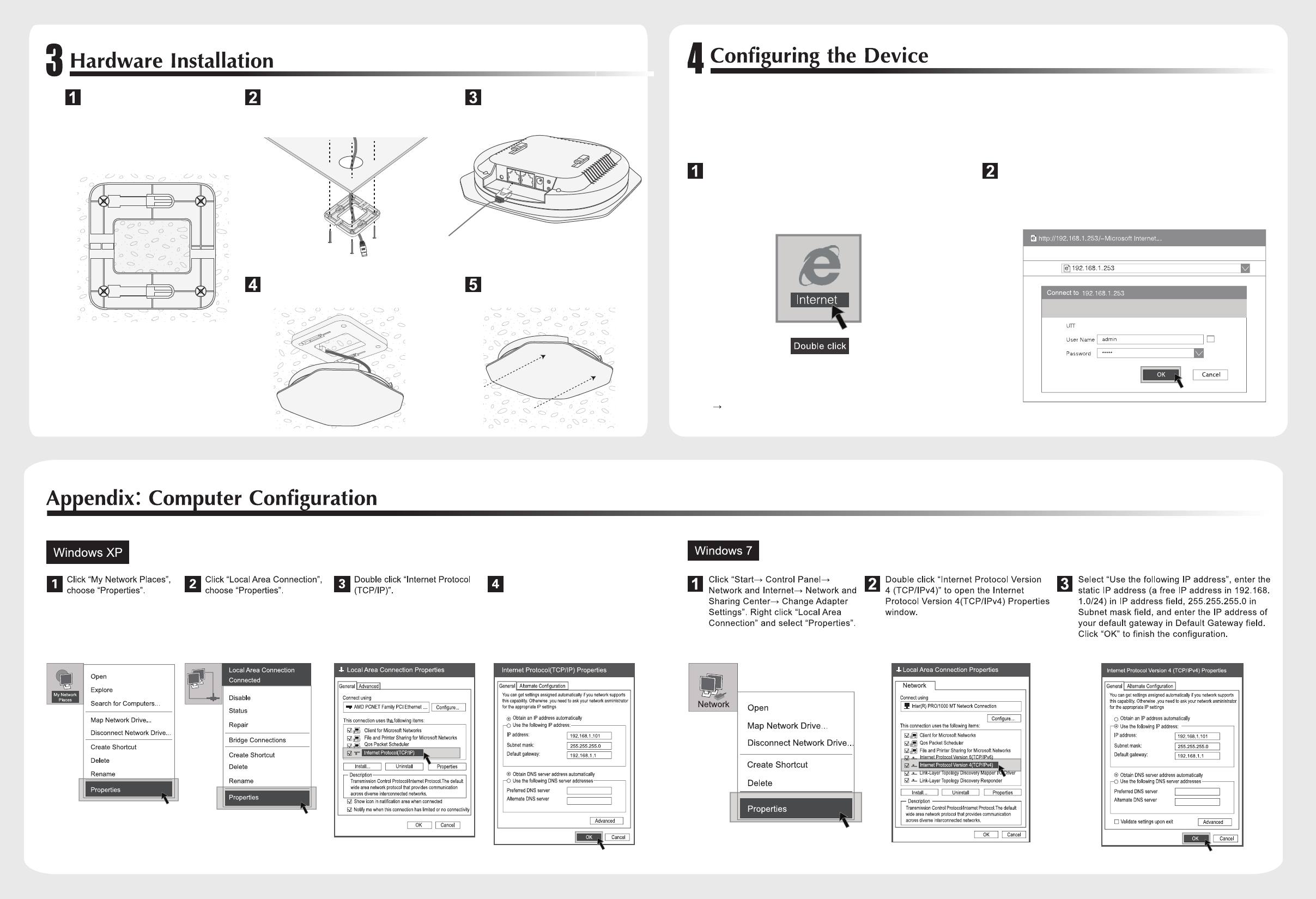
Select “Use the following IP address”,
enter the static IP address ( a free IP
address in 192.168.1.0/24) in IP address
field, 255.255.255.0 in Subnet mask
field, and enter the IP address of your
default gateway in Default Gateway field.
Click “OK” to finish the configuration.
Launch a web brouser, such as Internet Explorer or Mozilla
Firefox.
In the Address field enter the Device’s IP Address
(192.168.1.253) and press the Enter key.
Enter the default user name of admin and password of admin in
the User Name and Password fields. Click “OK” to access the
Device’s Web GUI.
NOTE: The Device works in FIT AP Mode by default. You can go to
“Start Device Mode” to change the Device Mode to FAT AP Mode.
2. If there is DHCP server on the local area network, the Device will obtain an IP address automatically.
NOTE:
1. Please assign your computer a static IP address within the same range as the Device’s IP address (192.168.1.253 by default). See more on
Appendix: Computer Configuration.
Secure the Mounting Bracket to the ceiling tile
by using the Expansion Bolts. Then feed the
Ethernet cable through the 25 mm hole.
Place the mounting bracket in the
center of the ceiling tile. Mark the
mounting screw holes and 25 mm
hole for the Ethernet cable. Use a
drill bit to drill the screw holes, and
cut or drill the 25 mm hole for the
Ethernet cable feed.
Connect the Ethernet cable to the
Ethernet port of the Device.
Align the notch on the Device with the
notch on the mounting bracket.
Turn the Device clockwise untill it
locks into place.
Caution: Any changes or modifications not expressly approved by the party responsible for compliance could void the user's authority to operate this equipment.
FCC Radiation Exposure Statement
This equipment complies with FCC RF radiation exposure limits set forth for an uncontrolled environment. This equipment should
be installed and operated with a minimum distance of 20 centimeters between the radiator and your body.