Ubee Interactive DVW32H Wiresless EMTA and WLCM User Manual 3030481
Ubee Interactive Corp. Wiresless EMTA and WLCM 3030481
User manual_rev 2.pdf
Ubee Interactive — www.ubeeinteractive.com
1 Ubee DVW32H – Safety and Installation Product Insert v1.1
DVW32H Advanced Wireless Voice
Gateway Safety and Installation Product
Insert
Federal Communications Commission
(FCC) Interference Statement
This device has been tested and found to comply
with the limits for a Class B digital device,
pursuant to Part 15 of the FCC Rules. These
limits are designed to provide reasonable
protection against harmful interference in a
residential installation. This device generates,
uses and can radiate radio frequency energy and,
if not installed and used in accordance with the
instructions, may cause harmful interference to
radio communications. However, there is no
guarantee that interference will not occur in a
particular installation. If this device does cause
harmful interference to radio or television
reception, which can be determined by turning
the equipment off and on, the user is encouraged
to try to correct the interference by one of the
following measures:
• Reorient or relocate the receiving antenna.
• Increase the separation between the
equipment and receiver.
• Connect the equipment into an outlet on a
circuit different from that to which the
receiver is connected.
• Consult the dealer or an experienced
radio/TV technician for help.
FCC Regulatory Information
This device complies with Part 15 of the FCC
Rules. Operation is subject to the following two
conditions: (1) This device may not cause
harmful interference, and (2) this device must
accept any interference received, including
interference that may cause undesired operation.
There is one statement for this product:
Ubee Interactive — www.ubeeinteractive.com
2 Ubee DVW32H – Safety and Installation Product Insert v1.1
• The device must carry a label stating “FCC
ID: XCNDVW32H.”
FCC Caution: Any changes or modifications not
expressly approved by the party responsible for
compliance could void the user's authority to
operate this device.
IEEE 802.11b or 802.11g operation of this device
in the U.S.A. is firmware-limited to channels 1
through 11.
FCC Radiation Exposure Statement:
This device complies with FCC radiation
exposure limits set forth for an uncontrolled
environment. This device should be installed and
operated at a minimum distance of 20cm
between itself and your body.
This device must not be co-located or operating
in conjunction with any other antenna or
transmitter.
Safety Notices
Read these instructions carefully before
operating the device. It is important to be aware
of these safety instructions. Install the device
according to these instructions and keep this
guide for future reference.
1. Do not use this device in a humid
space, in the rain, or near splashing
water.
2. Do not install during thunder or
lightening storms.
3. Do not cover any ventilation openings
in the device case.
4. Do not place the device near heat
sources such as radiators or stoves.
5. Clean the device only with a clean,
dry cloth. Do not use liquid or
chemical cleaners.
6. Avoid static discharge when touching
Ubee Interactive — www.ubeeinteractive.com
3 Ubee DVW32H – Safety and Installation Product Insert v1.1
the device by first touching the
coaxial connector of the coaxial
cable.
7. Installation of the device should
include grounding the coaxial cable
to the earth at the building entrance
per ANSI/NFPA 70 and the National
Electrical Code (NEC, in particular,
Section 820.93, Grounding of the
Outer Conductive Shield of a Coaxial
Cable).
8. The device is designed for IT power
systems with phase-to-phase voltage
at 100-240V.
9. Disconnecting the Device: If the
device becomes damaged or
encounters some other abnormality,
disconnect the power plug from the
AC wall outlet immediately.
10. The device should be installed in a
location not to exceed the maximum
temperature of 40 degrees Celsius
(104 degrees Fahrenheit).
11. When the device is placed upright
with the aid of the stand, the stand
must be fixed at a 90 degree angle to
the device. Otherwise, the device will
have the risk of tipping over. This is
the recommended position for best
Wi-Fi performance
12. Keep the device away from Children
and Pets
13. Place the device on a cool surface.
Failure to do so may result in
overheating which can cause
extreme damage.
14. Do not modify or attempt to
disassemble the device. Use it only
according to the instructions.
15. Do not dispose of the device in a
trash container. Please recycle.
Ubee Interactive — www.ubeeinteractive.com
4 Ubee DVW32H – Safety and Installation Product Insert v1.1
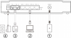
Installation
To install this device, follow the procedures
below and refer to the following page for a
connection diagram.
1. Connect one end of a coaxial cable (not
included) to the CABLE port on the device.
Connect the other end to a cable splitter or
the cable wall outlet. Be sure not to bend or
over tighten the cables as this may strain
the connector and cause damage. If you
plan to connect the device and a television
to the same cable wall outlet, you must use
a cable line splitter (not included).
2. Connect one end of the supplied Ethernet
cable to one of the LAN ports (LAN1 to
LAN4) on the device. Connect the other
end to the ETHERNET port (ETH1 to ETH4)
on a PC. Note: Category 5e or Category 6
Ethernet cables with RJ45 connectors must
be used when connecting Ethernet devices
to the LAN ports. This ensures Gigabit
Ethernet speeds (unless the computer
does not support it).
3. Connect one end of an RJ11 phone cable
to one of the TEL ports (TEL1 to TEL2) on
the device (a port that has been
provisioned for voice service as specified
by the service provider). Connect the other
end to the phone port of the telephone.
Note: If voice service is not provisioned
through the service provider, telephone
service is not available.
4. Connect the power adapter to the POWER
port on the device. Plug the other end of
the power adapter into the AC wall outlet.
Important: Use only the power adapter
that is shipped with the device.
Ubee Interactive — www.ubeeinteractive.com
5 Ubee DVW32H – Safety and Installation Product Insert v1.1
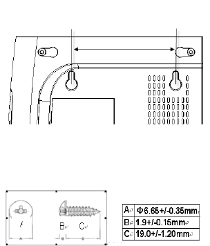
Wall-Mount Installation
You can mount the device on a wall using the 2
mounting brackets on the bottom of the device.
We recommend that you use two round or pan
head screws.
1. Install two screws horizontally apart on a
wall using the measurement shown to the
right. The screws should protrude from the
wall so that you can fit the device between
the head of the screw and the wall. If you
install the screws in drywall, use hollow
wall anchors to ensure that the unit does
not pull away from the wall due to
prolonged strain from the cable and power
connectors.
2. Remove the device from the product
package.
3. Mount the device on the wall.
4. Refer to the following figure.
The Distance of the Pothook (Horizontal)
The Screw’s Size (mm)
88mm (3.46 inches)
Ubee Interactive — www.ubeeinteractive.com
6 Ubee DVW32H – Safety and Installation Product Insert v1.1
Additional Information
1. RESET Button: To reset the device to
factory defaults. Using a pointed object,
insert it into the button opening, and hold
for more than 10 seconds. The device will
reset and reboot. Note: Not all parameters
are reset to factory defaults. Refer to the
User Guide for more information.
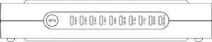
2. WPS button: The WPS button located on
the front of the Device, The Wi-Fi Protected
Setup method used to connect a PIN
protected Wi-Fi device to this Device.
LEDs and Other Device Indicators
See the following diagram and descriptions of the
device’s LED behavior, and the behavior of the
back-panel Ethernet indicators.
LED Indicators (Color = Green When On):
POWER/ READY—(POWER, Green) If On,
indicates that the device has successfully
completed internal power-on tests. LED flashes if
power-on fails. (READY, Blue) When the device
is obtaining an IP address and configuration file,
the LED flashes. When successfully complete,
the LED is On.
DS/US—LED flashes once every second while
scanning downstream, once locked, flashes
twice every second while scanning upstream,
solid when online. When the device performs a
firmware upgrade, the LED flashes. When
channel bonding, LED should be Blue otherwise
green.
Tel 1/Tel 2—The LED is On when a telephone is
on-hook. The LED flashes when a telephone is
off-hook.
Wi-Fi—The LED is on (Solid Green) when
enabled and blinking (green) when data is been
passed between the Device and the connected
Ubee Interactive — www.ubeeinteractive.com
7 Ubee DVW32H – Safety and Installation Product Insert v1.1
laptop, computer, etc.
WPS LED— When a user pushes the WPS
button or triggers WPS via the device’s web GUI,
this LED on the front of the device flashes Green
for 2 minutes until a PIN is entered from a
wireless client wishing to connect (e.g. a laptop
computer). After a Wi-Fi client attaches
successfully, the LED remains On (green) for 5
minutes, then turns Off.
LAN1/LAN2/LAN3/LAN4—The Ethernet ports
are used to connect Ethernet devices, such as
computers, gaming consoles, and/or
routers/hubs to the Device using RJ45 cables.
Each Ethernet port has an LED to indicate their
statuses when an Ethernet device is connected.
When an Ethernet device, is connected to the
cable modem, the LED is Green when connected
at 10/100 Mbps speeds. The LED is Blue when
connected at 1000 (Gigabit Ethernet) speed.
When data is being passed between the Device
and the connected laptop, computer, etc, the
LED flashes with same color scheme (i.e. green
for 10/100Mbps or blue for Gigabit).