Ubiqconn Technology GN01 Snap-on module User Manual 2IN1 UG 2013
Ubiqconn Technology, Inc. Snap-on module 2IN1 UG 2013
(SN201-GN01) UserMan
2-IN-1 Snap On module
U
UG
G

2
22
2-
--
-IN
ININ
IN-
--
-1SNAP ON MODULE
1SNAP ON MODULE1SNAP ON MODULE
1SNAP ON MODULE
User Guid
User GuidUser Guid
User Guid
e
ee
e
2
FCC Compliance Statement
This device complies with Part 15 of the FCC Rules. Operation is subject
to the following two conditions: (1) this device may not cause harmful
interference, and (2) this device must accept any interference received,
including interference that may cause undesired operation.
This equipment generates uses and can radiate radio frequency energy
and, if not installed and used in accordance with the instructions, may
cause harmful interference to radio communications. However, there is
no guarantee that interference will not occur in a particular installation. If
this equipment does cause harmful interference to radio or television
reception, which can be determined by turning the equipment off and on,
the user is encouraged to try to correct the interference by one or more
of the following measures:
-- Reorient or relocate the receiving antenna.
-- Increase the separation between the equipment and receiver.
-- Connect the equipment into an outlet on a circuit different from
that to which the receiver is connected.
-- Consult the dealer or an experienced radio/TV technician for
help.
FCC Caution: Any changes or modifications not expressly approved by the
party responsible for compliance could void the user's authority to operate
this equipment.

2
22
2-
--
-IN
ININ
IN-
--
-1SNAP ON MODULE
1SNAP ON MODULE1SNAP ON MODULE
1SNAP ON MODULE
User Guid
User GuidUser Guid
User Guid
e
ee
e
3
E
Eu
ur
ro
op
pe
e
–
–
E
EU
U
D
De
ec
cl
la
ar
ra
at
ti
io
on
n
o
of
f
C
Co
on
nf
fo
or
rm
mi
it
ty
y
This device complies with the essential requirements of the
R&TTE Directive 1999/5/EC and EMC directive 2004/108/EC. The
following test methods have been applied in order to prove
presumption of conformity with the essential requirements of the
R&TTE Directive 1999/5/EC and EMC directive 2004/108/EC:
<
EN 55022: 2010 + AC: 2011
<
EN 61000-3-2 : 2006 + A2 2009
<
EN 61000-3-3 : 2008
<
EN 55024: 2010
(IEC 61000-4-2: 2008;
IEC 61000-4-3: 2010;
IEC 61000-4-4: 2012;
IEC 61000-4-5: 2005;
IEC 61000-4-6: 2008;
IEC 61000-4-8: 2009;
IEC 61000-4-11: 2004)
<
EN 60950-1: 2005 + A1
Safety of information technology equipment
<
EN 300 328 V1.7.1: 2006
<
EN 302 291 -1/ -2
<
EN 62311: 2008

2
22
2-
--
-IN
ININ
IN-
--
-1SNAP ON MODULE
1SNAP ON MODULE1SNAP ON MODULE
1SNAP ON MODULE
User Guid
User GuidUser Guid
User Guid
e
ee
e
4
Specification
The 2-IN-1SNAP ON MODULE is a flexible, With following specifications
that can be applied in diverse operational environments and implemented
in multi-faceted applications.
Barcode Scanner :
< Decoded Mode :
1D Symbologies : EAN/UPC, RSS, Code 39, Code 128,
UCC/EAN 128, ISBN, ISBT, Interleaved, Matrix, Industrial
and Standard 2 of 5, Codabar, Code 93/93i, Code 11, MSI,
Plessey, Telepen, postal codes.
2D Symbologies: Data Matrix, PDF417, Micro PDF 417,
Maxicode, QR, Aztec, EAN.UCC composite.
GPS :
< Channel :
50 channel all-in-view tracking
GPS,GLONASS support
1 x Signal Color LED (Blue)
CAC :
Supports ISO/IEC 7816 standard
Supports PC Smart Card industry standard: PC/SC 1.0 & 2.0
Works with 5V, 3V and 1.8V Smart cards

2
22
2-
--
-IN
ININ
IN-
--
-1SNAP ON MODULE
1SNAP ON MODULE1SNAP ON MODULE
1SNAP ON MODULE
User Guid
User GuidUser Guid
User Guid
e
ee
e
5
GPS :
'- ISO/IEC 14443A, 14443B, 15693
- Mifare 1K/4K, Ultralight
- NFC-IP1 Protocol
2
22
2-
--
-IN
ININ
IN-
--
-1SNAP ON MODULE
1SNAP ON MODULE1SNAP ON MODULE
1SNAP ON MODULE
User Guid
User GuidUser Guid
User Guid
e
ee
e
6
U
Us
si
in
ng
g
a
a
B
Ba
ar
rc
co
od
de
e
S
Sc
ca
an
nn
ne
er
r
/
/G
GP
PS
S
M
Mo
od
du
ul
le
e
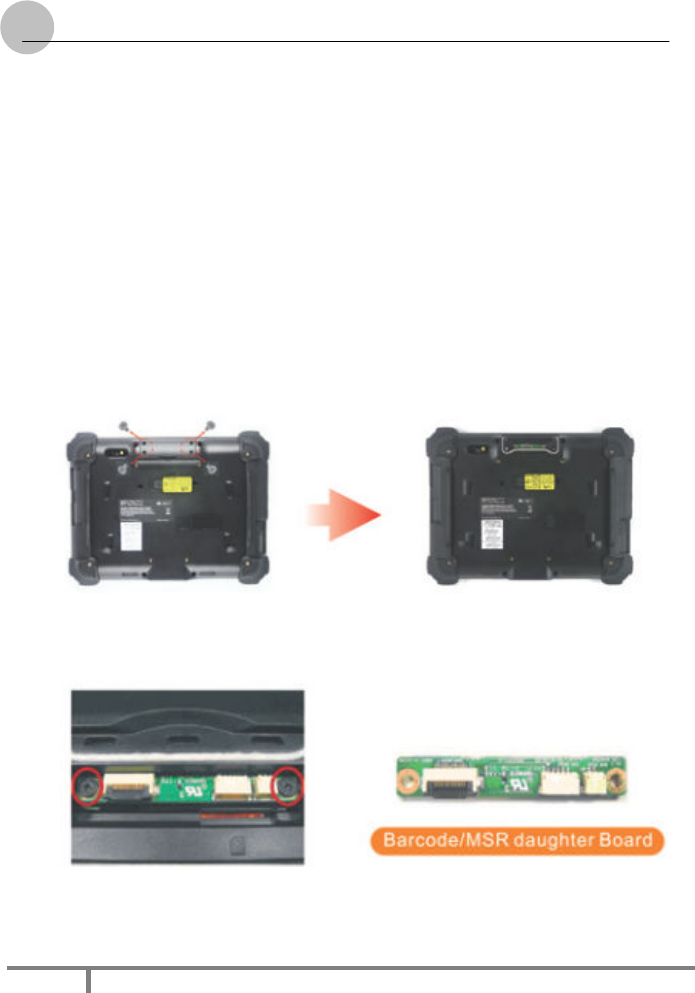
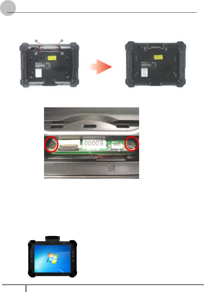
The System provides barcode scanner/GPS functions for your optional
selection, before installing either of these two modules on the top side of
the system, please remove the screws previously (illustrated in the
following graphics as indicated step 1).
To install the Barcode Scanner/GPS Module:
1. Make sure the system is turned off. Unscrew four screws from the
accessory door on top of the system.
2. Mount and secure the Barcode daughter board into the
mainboard with screws.
2
22
2-
--
-IN
ININ
IN-
--
-1SNAP ON MODULE
1SNAP ON MODULE1SNAP ON MODULE
1SNAP ON MODULE
User Guid
User GuidUser Guid
User Guid
e
ee
e
7
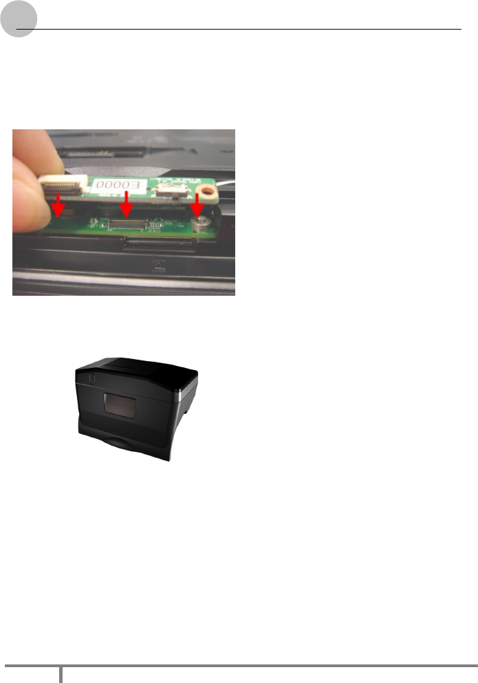
3. Insert FFC cable of barcode scanner into connector slot or
attached the GPS cable to the connectors on the daughter
board.
4. Screw to secure the Barcode Scanner/GPS onto the tablet.
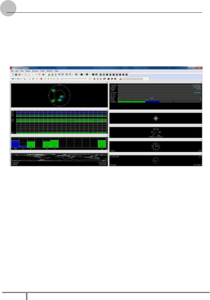
GPS:
1). Set baud rate to 9600bps
2). Connect to GPS module via appropriate serial port#
→ For GP01 (on main tablet unit): please check under device
manager under COM&LPT ports, choose the Enhanced
2
22
2-
--
-IN
ININ
IN-
--
-1SNAP ON MODULE
1SNAP ON MODULE1SNAP ON MODULE
1SNAP ON MODULE
User Guid
User GuidUser Guid
User Guid
e
ee
e
8
COM port# corresponding to 1
st
set of "Silicon Labs Dual CP210x
USB to UART Bridge: “Enhanced” COM Port
(COMx)
U
Us
si
in
ng
g
a
a
N
NF
FC
C
/
/G
GP
PS
S
M
Mo
od
du
ul
le
e
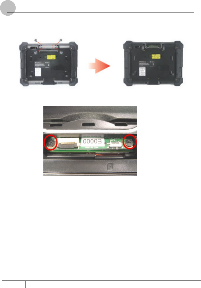
The System provides NFC/GPS functions for your optional selection,
before installing either of these two modules on the top side of the system,
please remove the screws previously (illustrated in the following graphics
as indicated step 1).
To install the NFC/GPS Module:
2
22
2-
--
-IN
ININ
IN-
--
-1SNAP ON MODULE
1SNAP ON MODULE1SNAP ON MODULE
1SNAP ON MODULE
User Guid
User GuidUser Guid
User Guid
e
ee
e
9
5. Make sure the system is turned off. Unscrew four screws from the
accessory door on top of the system.
6. Mount and secure the Daughter board into the mainboard
with screws.
7. Insert FFC cable of barcode scanner into connector slot or
attached the NFC/GPS cable to the connectors on the daughter
board.
8. Screw to secure the NFC/GPS onto the tablet.
9. The RFID read range of this module will vary from
approximately 40 ~50mm depending on the following factors;
2
22
2-
--
-IN
ININ
IN-
--
-1SNAP ON MODULE
1SNAP ON MODULE1SNAP ON MODULE
1SNAP ON MODULE
User Guid
User GuidUser Guid
User Guid
e
ee
e
10
9.1. The shape and size of the RFID tag. Large Size RFID tags have
longer read range (Smaller tags have a smaller RF
radiating field)
9.2. Any metallic objects near the RFID tag will effectively reduce
the read range
9.3. Any electrical interference from surrounding electrical
equipment may reduce read range.
U
Us
si
in
ng
g
a
a
C
CA
AC
C
/
/G
GP
PS
S
M
Mo
od
du
ul
le
e
The System provides CAC/GPS functions for your optional selection,
before installing either of these two modules on the top side of the system,
please remove the screws previously (illustrated in the following graphics
as indicated step 1).
To install the CAC/GPS Module:
2
22
2-
--
-IN
ININ
IN-
--
-1SNAP ON MODULE
1SNAP ON MODULE1SNAP ON MODULE
1SNAP ON MODULE
User Guid
User GuidUser Guid
User Guid
e
ee
e
11
9. Make sure the system is turned off. Unscrew four screws from the
accessory door on top of the system.
10. Mount and secure the Daughter board into the mainboard
with screws.
11. Insert FFC cable of barcode scanner into connector slot or
attached the CAC/GPS cable to the connectors on the daughter
board.
12. Screw to secure the CAC/GPS onto the tablet.