Ubiquiti AF4X Dual Channel OFDM MIMO Point to Point Device User Manual airFiber X User Guide
Ubiquiti Networks, Inc. Dual Channel OFDM MIMO Point to Point Device airFiber X User Guide
Ubiquiti >
Contents
- 1. Users Manual pt 1
- 2. Users Manual pt 2
- 3. Users Manual pt 3
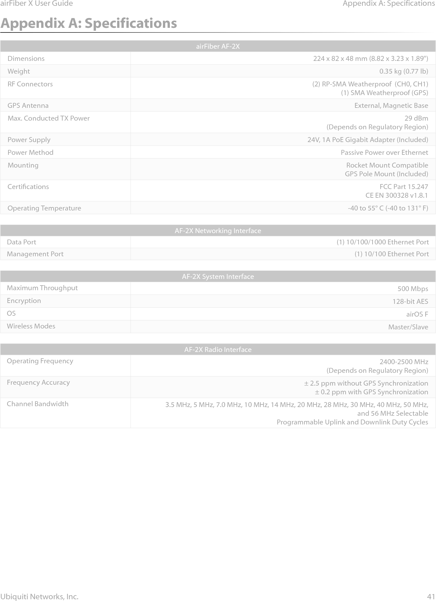
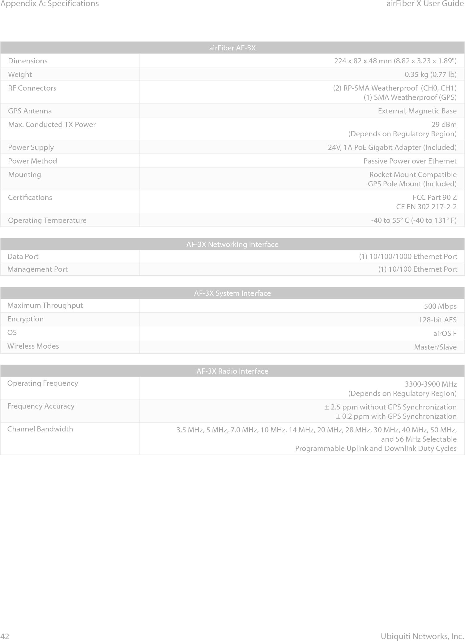
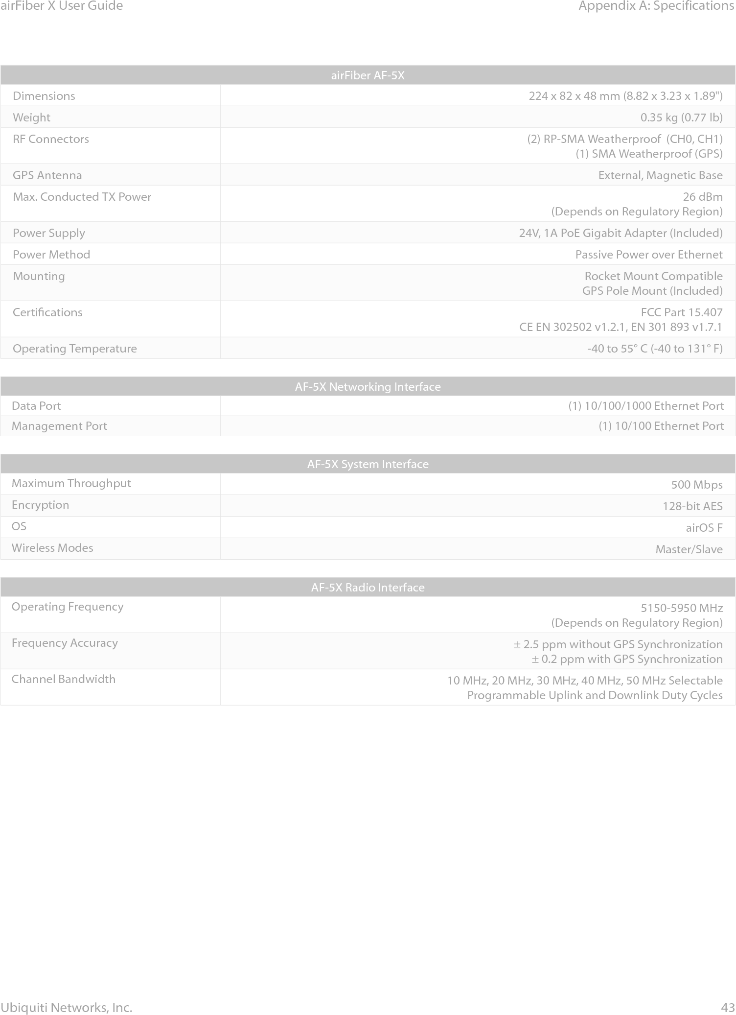
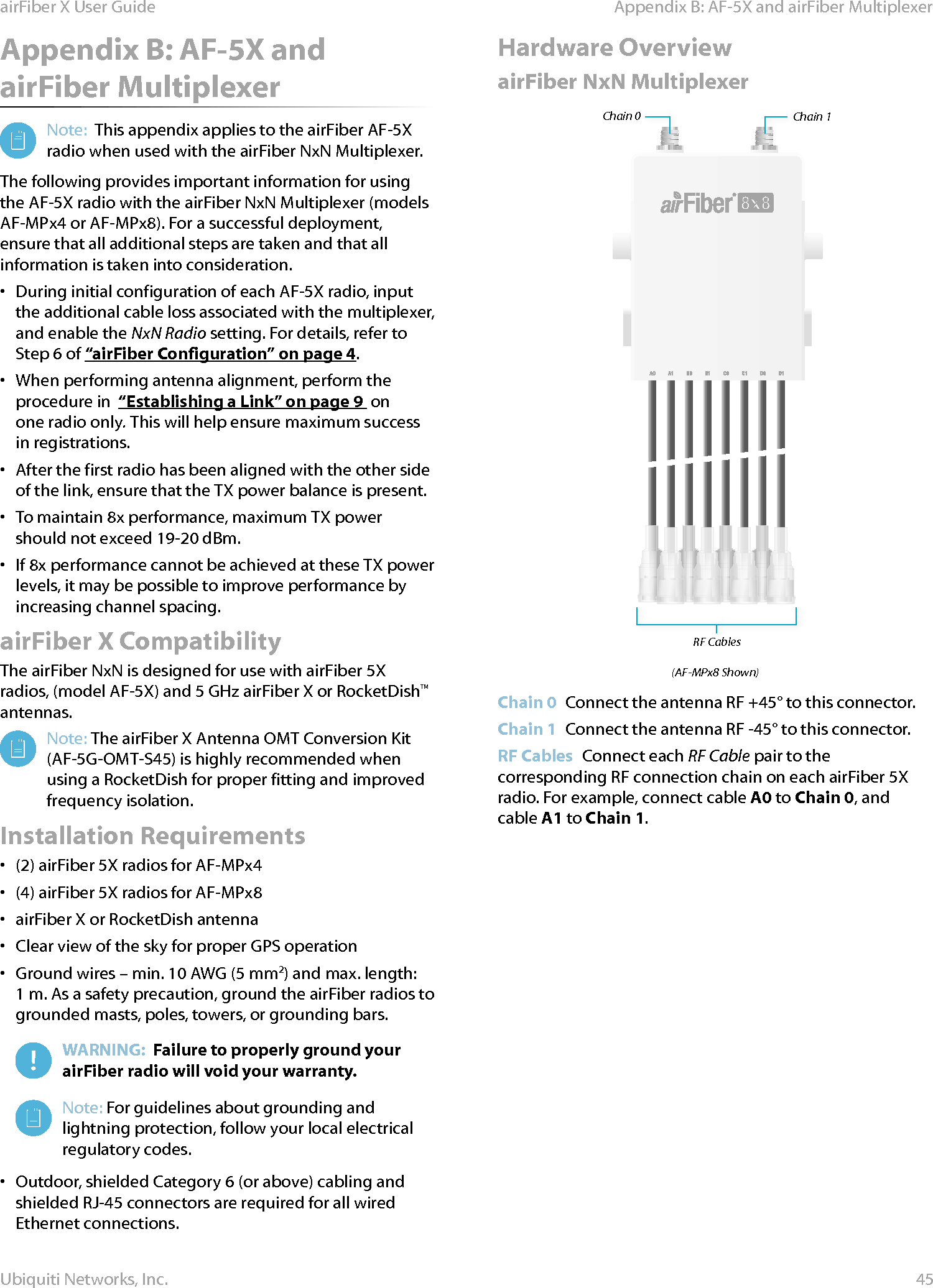
- 4. Users Manual pt 4
- 5. Users Manual pt 5
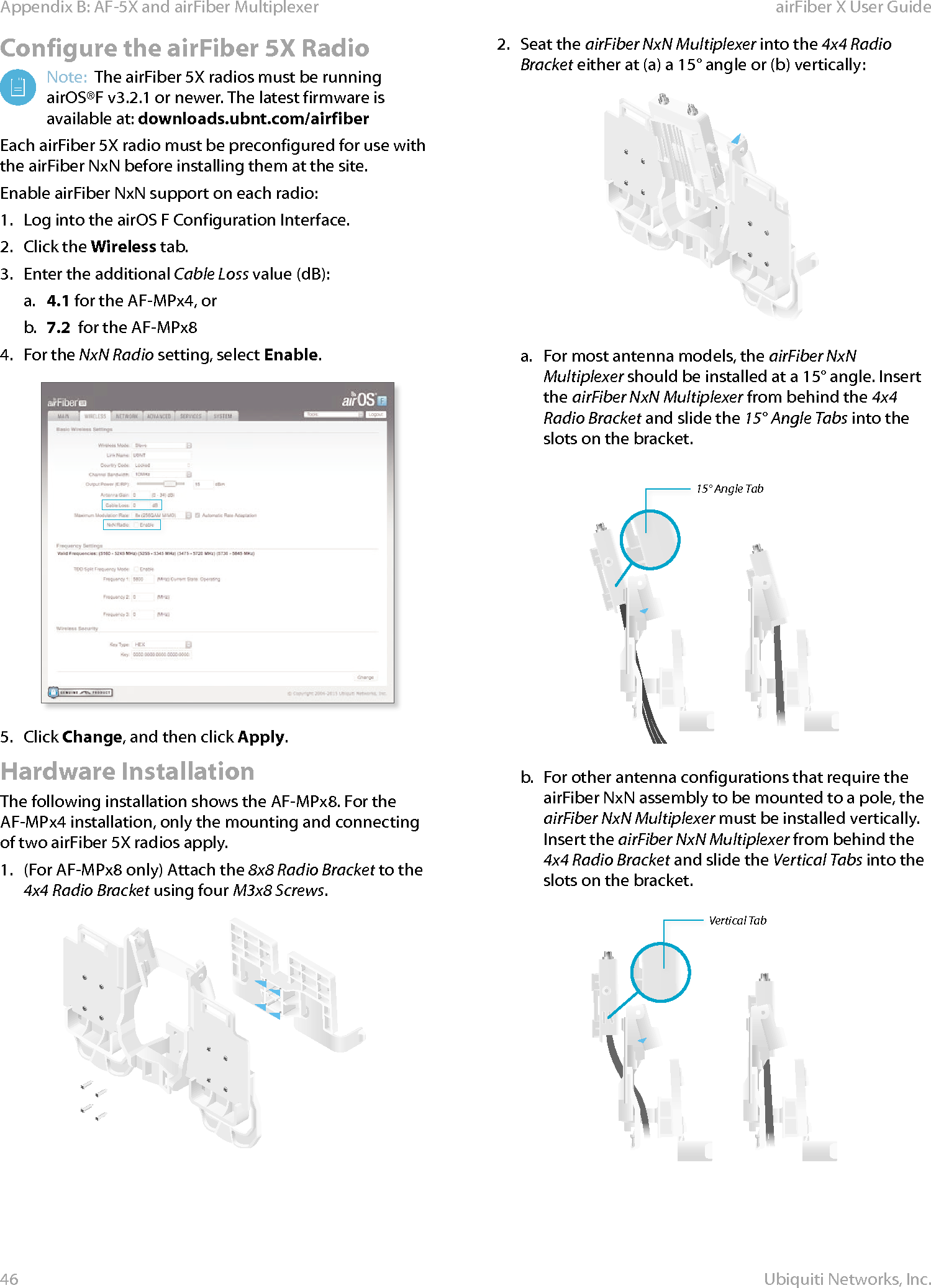
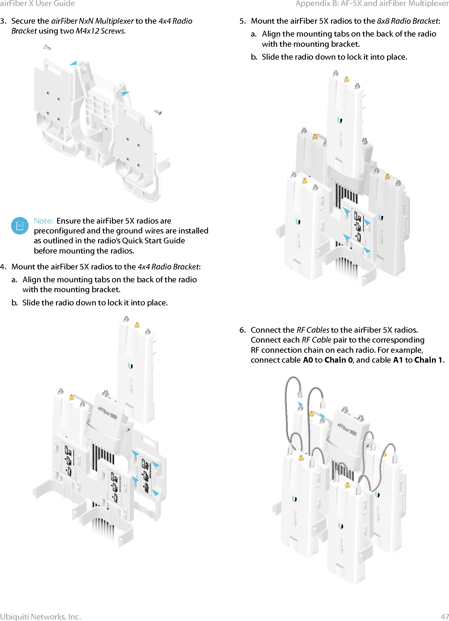
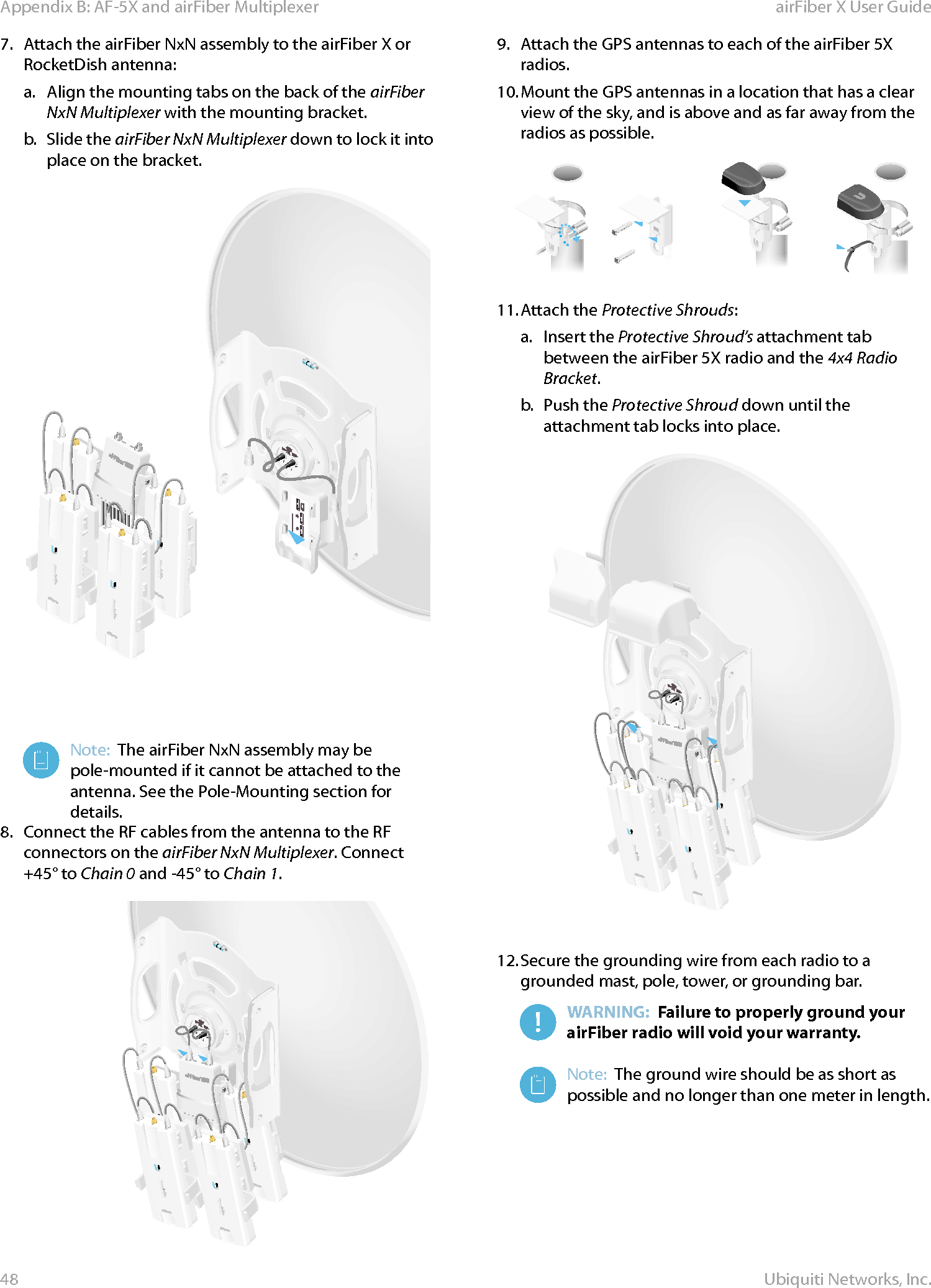
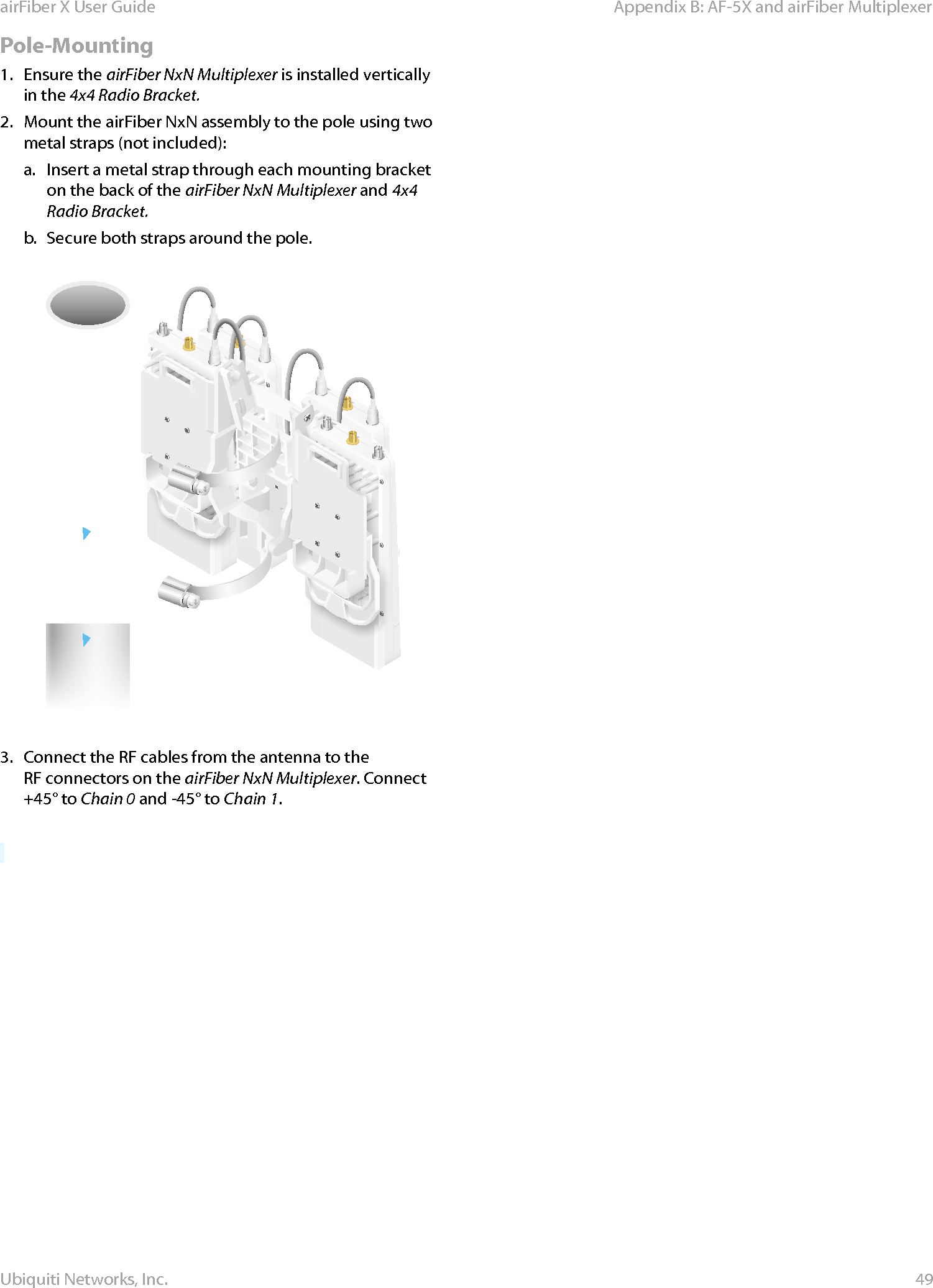
Users Manual pt 4