Ubiquiti AF4X Dual Channel OFDM MIMO Point to Point Device User Manual airFiber X User Guide
Ubiquiti Networks, Inc. Dual Channel OFDM MIMO Point to Point Device airFiber X User Guide
Ubiquiti >
Contents
- 1. Users Manual pt 1
- 2. Users Manual pt 2
- 3. Users Manual pt 3
- 4. Users Manual pt 4
- 5. Users Manual pt 5
Users Manual pt 1

2.4 GHz, 3 GHz, 4 GHz, 5 GHz
Carrier Backhaul Radio
Model: AF-2X, AF-3X, AF-4X, AF-5X

i
Table of ContentsairFiber X User Guide
Ubiquiti Networks, Inc.
Table of Contents
Chapter 1: Overview ................................................1
Introduction. . . . . . . . . . . . . . . . . . . . . . . . . . . . . . . . . . . . . . . . . . . . . . . . . . . . . . . . . . . . . . . . . . . . . . 1
Package Contents ................................................................1
airFiber Configuration Interface SystemRequirements ............................1
Hardware Overview ..............................................................1
Chapter 2: Installation ..............................................3
Installation Requirements ........................................................3
Installation Overview .............................................................3
Connecting Power over Ethernet ..................................................3
airFiber Configuration ............................................................4
Hardware Installation .............................................................5
Alignment .......................................................................9
Installer Compliance Responsibility ..............................................10
Chapter 3: Navigation .............................................11
Accessing the airFiber Configuration Interface ...................................11
Product Verification .............................................................12
Interface Tabs ...................................................................12
Chapter 4: Main Tab ...............................................13
Status ...........................................................................13
Ethernet. . . . . . . . . . . . . . . . . . . . . . . . . . . . . . . . . . . . . . . . . . . . . . . . . . . . . . . . . . . . . . . . . . . . . . . . .15
Monitor .........................................................................15
Chapter 5: Wireless Tab ............................................17
Basic Wireless Settings ...........................................................17
Frequency Settings ..............................................................19
Wireless Security ................................................................19
Chapter 6: Network Tab ...........................................21
Management Network Settings ..................................................21
Chapter 7: Advanced Tab ..........................................23
Wireless Settings ................................................................23
DATA Port Ethernet Settings .....................................................24
MGMT Port Ethernet Settings ....................................................25
ii
Table of Contents airFiber X User Guide
Ubiquiti Networks, Inc.
Chapter 8: Services Tab ............................................27
Ping Watchdog ..................................................................27
SNMP Agent. . . . . . . . . . . . . . . . . . . . . . . . . . . . . . . . . . . . . . . . . . . . . . . . . . . . . . . . . . . . . . . . . . . . .28
Telnet Server ....................................................................29
NTP Client .......................................................................29
Dynamic DNS ...................................................................29
System Log ......................................................................29
Device Discovery ................................................................29
Chapter 9: System Tab .............................................31
Firmware Update ................................................................31
Device ..........................................................................32
Date Settings ....................................................................32
System Accounts ................................................................32
Miscellaneous ...................................................................32
Location ........................................................................33
Device Maintenance .............................................................33
Configuration Management .....................................................33
Chapter 10: Tools ..................................................35
Align Antenna ...................................................................35
Discovery .......................................................................36
Ping .............................................................................36
Traceroute ......................................................................36
airView ..........................................................................36
Appendix A: Specifications ........................................41
Appendix B: AF-5X and airFiber Multiplexer ........................45
airFiber X Compatibility ..........................................................45
Installation Requirements .......................................................45
Hardware Overview .............................................................45
Configure the airFiber 5X Radio ..................................................46
Hardware Installation ............................................................46
Appendix C: Listen Before Talk .....................................51
Introduction. . . . . . . . . . . . . . . . . . . . . . . . . . . . . . . . . . . . . . . . . . . . . . . . . . . . . . . . . . . . . . . . . . . . .51
Unrestricted Protocol Description ................................................51
Threshold Detection To Determine Occupancy ...................................51
Action Taken When Occupancy is Determined ...................................51
Opportunities for Other Transmitters to Operate .................................52
iii
Table of ContentsairFiber X User Guide
Ubiquiti Networks, Inc.
Appendix D: Safety Notices ........................................53
Electrical Safety Information .....................................................53
Appendix E: Warranty .............................................55
Limited Warranty ................................................................55
Appendix F: Compliance Information ..............................57
Installer Compliance Responsibility ..............................................57
FCC .............................................................................57
Industry Canada .................................................................59
RF Exposure Warning ............................................................61
Australia and New Zealand ......................................................61
CE Marking ......................................................................62
airFiber AF-4X Compliance .......................................................62
Frequency Ranges and Power Levels per Country/Region ........................63
RoHS/WEEE Compliance Statement ..............................................69
Appendix G: Declaration of Conformity ............................71
Appendix H: Contact Information ..................................73
Ubiquiti Networks Support ......................................................73
iv
Table of Contents airFiber X User Guide
Ubiquiti Networks, Inc.
1
Chapter 1: OverviewairFiber X User Guide
Ubiquiti Networks, Inc.
airFiber Configuration Interface
SystemRequirements
• Microsoft Windows 7, Windows 8; Linux; or Mac OS X
• Java Runtime Environment 1.6 (or above)
• Web Browser: Mozilla Firefox, Apple Safari,
GoogleChrome, Microsoft Edge, or Microsoft Internet
Explorer11
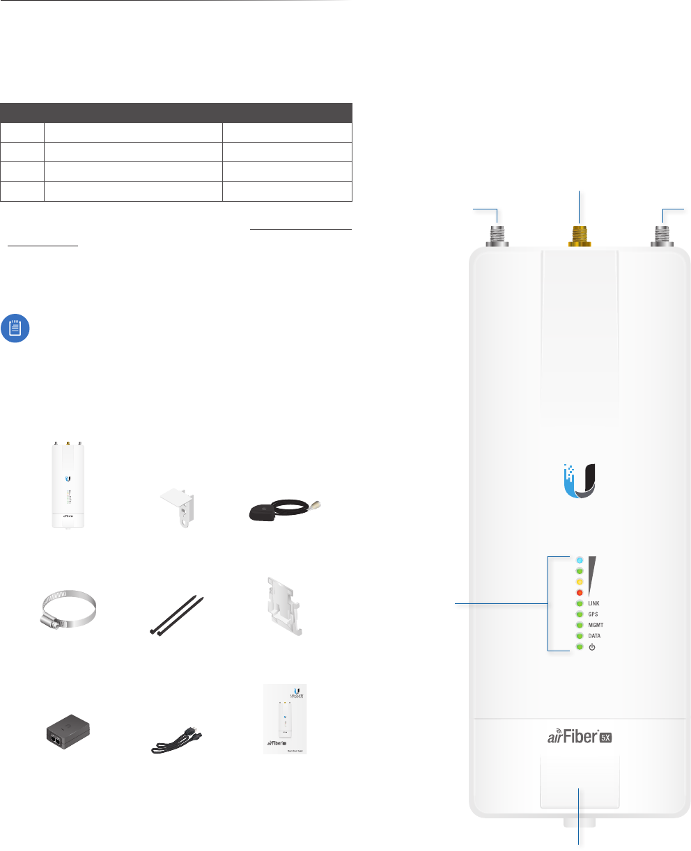
Hardware Overview
Port Cover
LED
Panel
Connects to
External GPS
Antenna
Chain 0:
Connects to
+45° on
airFiber Antenna
Chain 1:
Connects to
-45° on
airFiber Antenna
Chapter 1: Overview
Introduction
Thank you for purchasing the Ubiquiti Networks®
airFiber® X Carrier Backhaul Radio. This User Guide is for
use with the following models:
Model Description Operating Frequency*
AF-2X 2.4 GHz Carrier Backhaul Radio 2400 - 2500 MHz
AF-3X 3 GHz Carrier Backhaul Radio 3300 - 3900 MHz
AF-4X 4 GHz Carrier Backhaul Radio 4940-4990 MHz
AF-5X 5 GHz Carrier Backhaul Radio 5150 - 5925 MHz
* Depends on Regulatory Region. Refer to “Specifications”
on page 41 for more information.
This User Guide provides installation instructions, explains
how to set up an airFiber link, and shows how to access
and use the airFiber Configuration Interface.
Note: Throughout this User Guide, airFiberX radio
refers to all models listed above. Unless noted
otherwise, illustrations for a specific model are
applicable to all airFiberX radio models and
accessories.
Package Contents
airFiber AF-2X, AF-3X,
AF-4X, or AF-5X
GPS Antenna Mount External GPS Antenna
Metal Strap Cable Ties
(Qty. 2) Universal Bracket
(AF-4X and AF-5X only)
5 GHz Carrier
Backhaul Radio
Model: AF-5X
DATA
MGMT
GPS
LINK
DATA
MGMT
GPS
LINK
airFiber PoE (24V, 1A)
with Mounting Bracket
Power Cord Quick Start Guide
TERMS OF USE: Ubiquiti radio devices must be professionally installed. Shielded Ethernet cable and
earth grounding must be used as conditions of product warranty. TOUGHCable™ is designed for
outdoor installations. It is the customer’s responsibility to follow local country regulations, including
operation within legal frequency channels, output power, and Dynamic Frequency Selection (DFS)
requirements.
2
Chapter 1: Overview airFiber X User Guide
Ubiquiti Networks, Inc.
Ports
Reset
Button
Management
Port
Data
Port
Management Port 10/100 Mbps, secured Ethernet
port for configuration. In-Band Management is enabled
by default in the airFiber Configuration Interface. When
In-Band Management is disabled, the MGMT port is the
only port that can monitor, configure, and/or update
firmware.
Reset Button To reset to factory defaults, press and hold
the Reset button for more than 10 seconds while the
device is already poweredon.
Data Port Gigabit PoE port for handling all user traffic
and powering the device.
LEDs
Signal LEDs
Signal 4 LED will light blue when on.
Signal 3 LED will light green when on.
Signal 2 LED will light yellow when on.
Signal 1 LED will light red when on.
Bootup to airOS When powering on, the Power, GPS,
LINK, and Signal 1-4 LEDs light on. Once the CPU code
takes over, the GPS, LINK, and Signal 1-3 LEDs turn off.
Signal 4 LED remains on to indicate the boot sequence is
underway.
Initializing airFiber Software When the airFiber
application begins to boot under airOS, the Signal 4 LED
goes from solidly on to a 2.5 Hz flash. This continues until
the airFiberX radio is fully booted.
Signal Level Once fully booted, the Signal 1-4 LEDs act
as a bar graph showing how close the airFiberX radio
is to ideal aiming. This is auto-scaled based on the link
range, the antenna gains, and the configured TX power
of the remote airFiberX radio. Each Signal LED has three
possible states: On, Flashing, and Off. All Signal LEDs would
be solidly on in an ideal link. If the link has a 1 dB loss, the
Signal4 LED will flash; a 2 dB loss and the Signal 4 LED will
turn off. The full bar graph LED states are shown below.
dB
loss 0 -1 -2 -3 -4 -5 -6 -7 -8 -9 -10 -11 -12 -13
1 F 0 0 0 0 0 0 0 0 0 0 0 0
1 1 1 F 0 0 0 0 0 0 0 0 0 0
1 1 1 1 1 F F 0 0 0 0 0 0 0
1111111111 F F F 0
0 = Off, 1 = On, F = Flashing
Additional LEDs
LED State Status
LINK
Off RF Off
Short Flash* Syncing
Normal Flash* Beaconing
Long Flash* Registering
On Operational
GPS
Off No GPS Synchronization
Normal Flash* Non-Operational (Weak Signal)
On Operational (Strong Signal)
MGMT
Off No Ethernet Link
On Ethernet Link Established
Random Flashing Ethernet Activity
DATA
Off No Ethernet Link
On Ethernet Link Established
Random Flashing Ethernet Activity
Off No Power
On Powered On
* Short Flash (1:3 on/off cycle)
Normal Flash (1:1 on/off cycle)
Long Flash (3:1 on/off cycle)
3
Chapter 2: InstallationairFiber X User Guide
Ubiquiti Networks, Inc.
Chapter 2: Installation
Installation Requirements
The airFiberradio operates only with the antennas listed
below:
airFiberRadio airFiberX Antenna RocketDish + Conversion Kit
AF-2X AF-2G24-S45 n/a
AF-3X AF-3G26-S45 n/a
AF-4X AF-5G30-S45
AF-5G34-S45
RD-5G30 + AF-5G-OMT-S45
RD-5G34 + AF-5G-OMT-S45
AF-5X
AF-5G23-S45
AF-5G30-S45
AF-5G34-S45
RD-5G30 + AF-5G-OMT-S45
RD-5G34 + AF-5G-OMT-S45
See the antenna’s Quick Start Guide for antenna
installation instructions.
Other Requirements
• Clear line of sight between airFiberX radios
• Clear view of the sky for proper GPS operation
• Vertical mounting orientation
• Mounting point:
• At least 1 m below the highest point on the structure
• For tower installations, at least 3 m below the top of
thetower
• Ground wires – min. 10 AWG (5 mm2) and max. length:
1m. Asa safety precaution, ground the airFiberX radio
to grounded masts, poles, towers, or grounding bars.
WARNING: Failure to properly ground your
airFiberX radio will void your warranty.
• (Recommended) 2 Outdoor Gigabit PoE surge protectors
Note: For guidelines about grounding and
lightning protection, follow your local electrical
regulatory codes.
• Outdoor, shielded Category 6 (or above) cabling and
shielded RJ-45 connectors are required for all wired
Ethernet connections.
Installation Overview
We recommend to configure your paired airFiberX radios
before site installation. The overview below summarizes
the installation procedure, and the subsequent sections
provide detailed installation information:
• Connect the airFiber PoE Adapter to the DATA port, and
connect your computer and the MGMTport.
• Configure the airFiberX radio.
• Install a ground wire and mount the airFiberX radio on
an airFiberX antenna.
• At the installation site, install the airFiberX antenna with
the mounted airFiberX radio (see the antenna’s Quick
Start Guide for installation instructions).
• Secure the ground wire and mount the GPS antenna.
• Establish and optimize the RF link.
Connecting Power over Ethernet
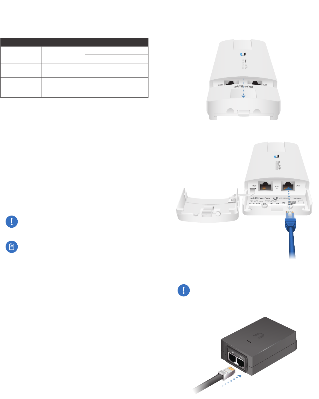
1. Lift the release latch on the bottom of the airFiberX
radio and slide the Port Cover off.
2. Connect an Ethernet cable to the DATA port.
3. Connect the Ethernet cable from the DATA port to the
Ethernet port labeled POE on the airFiber PoE Adapter.
WARNING: Use only the included airFiber PoE
adapter, Model GP-H240-100G-4. Failure to do
so can damage the unit and void the product
warranty.
4
Chapter 2: Installation airFiber X User Guide
Ubiquiti Networks, Inc.
4. Connect the Power Cord to the power port on the
airFiber PoE Adapter. Connect the other end of the
Power Cord to a powersource.
airFiber Configuration
The instructions in this section explain how to access
the airFiber Configuration Interface and configure the
following settings:
• Wireless Mode Configure one airFiberX radio as the
Master and the other as the Slave.
• Frequency Setting The operating Frequency must be
the same on both the Master and the Slave.
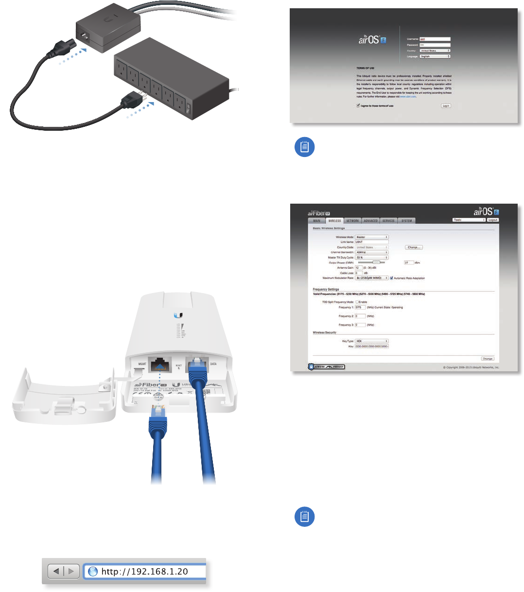
1. Connect an Ethernet cable from your computer to the
MGMT port on the airFiberX radio.
2. Configure the Ethernet adapter on your computer with
a static IP address on the 192.168.1.x subnet.
3. Launch your web browser. Type http://192.168.1.20 in
the address field and press enter (PC) or return (Mac).
4. The login screen will appear. Enter ubnt in the
Username and Password fields. Select your Country and
Language. You must agree to the Terms of Use to use
the product. Click Login.
Note for models AF-2X, AF-3X, and AF-5X only:
U.S. product versions are locked to the U.S.
Country Code to ensure compliance with FCC
regulations.
5. Click the Wireless tab.
6. Configure the Basic Wireless Settings:
a. For one airFiberX radio, select Master as the
Wireless Mode. For the other airFiberX radio, keep
the default,Slave.
b. Enter a name in the Link Name field. This should be
the same on both the Master and the Slave.
c. If needed, change the Channel Bandwidth, (Master)
Duty Cycle, Output Power, Cable Loss (see Note
below), and/or Maximum Modulation Rate settings.
Note: If you are using the airFiber AF-5X radio
with an airFiber Multiplexer, perform the
following additional steps:
d. Set the CableLoss to a value that includes the
additional loss (in dB) due to the Multiplexer.
The additional cable loss is (approximately):
• 4 dB for the AF-MPx4, or
• 7 dB for the AF-MPx8
e. Enable the NxN Radio setting on each end of
the link.
5
Chapter 2: InstallationairFiber X User Guide
Ubiquiti Networks, Inc.
7. Configure the Frequency Settings. The selected
Frequency must be the same on both airFiberX radios.
8. Configure the Wireless Security:
a. Select the AES Key Type, HEX or ASCII.
b. For the Key field:
-HEX Enter 16 bytes (eight, 16-bit HEX values: 0-9,
A-F, or a-f ). You can omit zeroes and use colons,
similar to the IPv6 format.
Note: The airFiber Configuration Interface
supports IPv6 formats excluding dotted
quad and “::” (double-colon) notation.
-ASCII Enter a combination of alphanumeric
characters (0-9, A-Z, or a-z).
9. Click Change and then click Apply.
10. In-Band Management is enabled by default, so each
airFiberX radio must have a unique IP Address. (If the
airFiberX radios use the same IP Address, you may lose
access to the airFiberX radios via the DATA ports.) Click
the Network tab.
a. For the Management IP Address option:
-DHCP Keep the default, DHCP, to use DHCP
reservation on your router to assign a unique
IPAddress.
-Static Change the IP Address, Netmask, and other
settings to make them compatible with your
network.
b. Click Change and then click Apply.
Repeat the instructions in the airFiber Configuration
section on your other airFiberX radio. After you have
configured the airFiberX radios, disconnect them and
move them to your installation site.
Hardware Installation
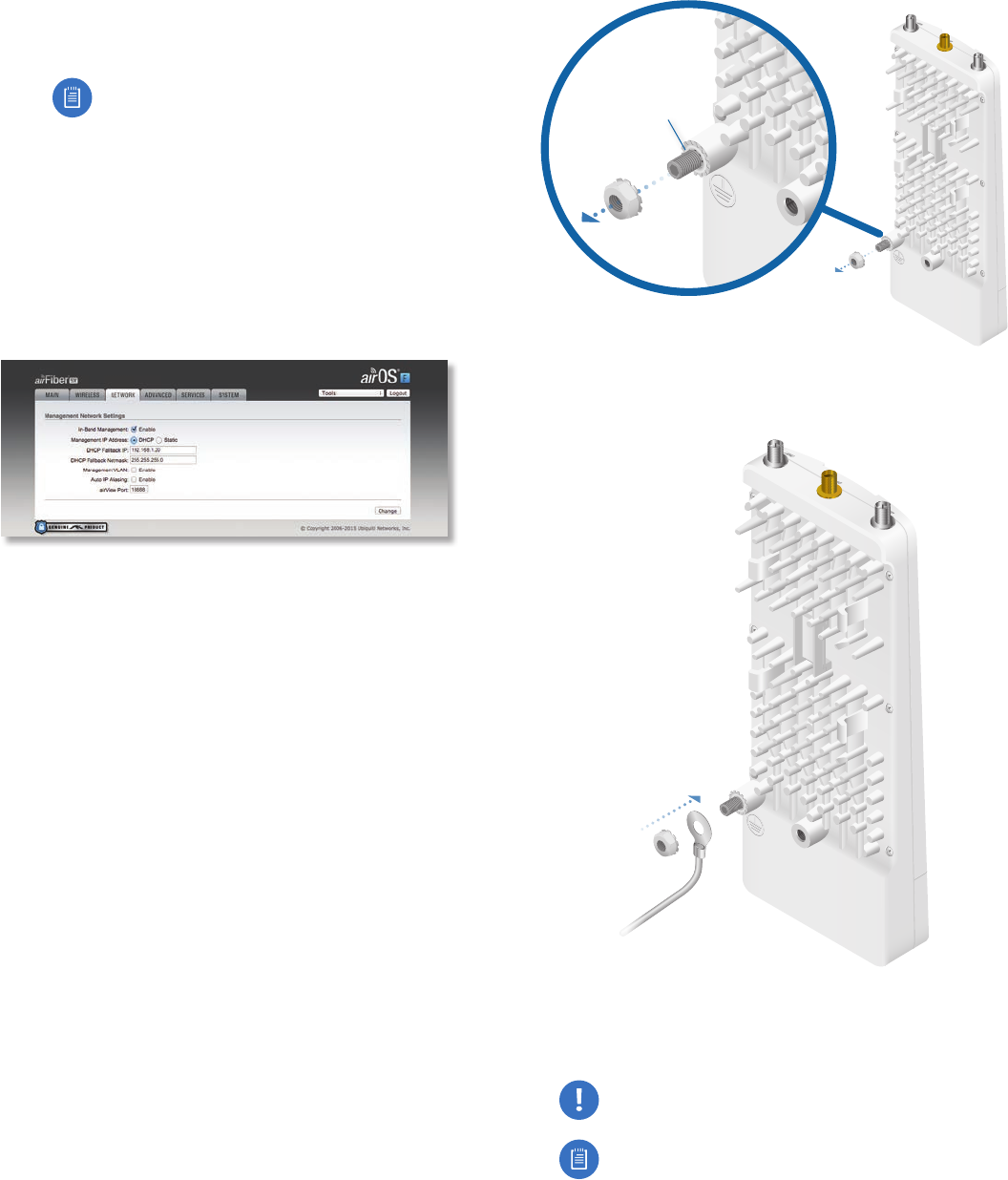
Install a Ground Wire
1. Remove the nut from the Ground Bonding Point located
on the back of the airFiberX radio.
Ground
Bonding
Point
2. Attach a ground wire (min. 10 AWG or 5 mm2) to the
lug and replace the nut to secure the wire.
3. At the installation site, secure the other end of the
ground wire to a grounded mast, pole, tower, or
grounding bar.
WARNING: Failure to properly ground your
airFiberX radio will void your warranty.
Note: The ground wire should be as short as
possible and no longer than one meter in length.
6
Chapter 2: Installation airFiber X User Guide
Ubiquiti Networks, Inc.
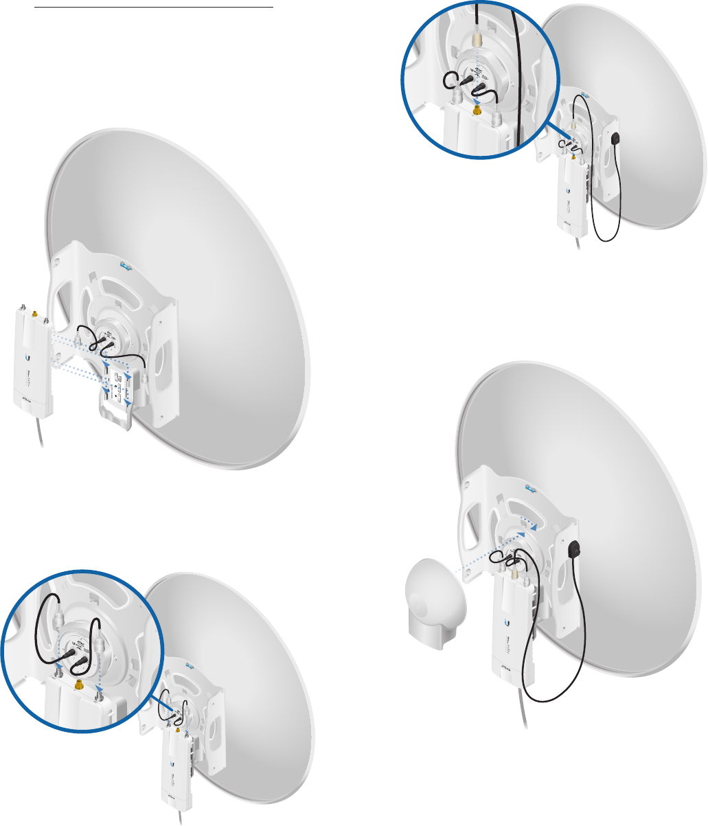
Mount to an Antenna
The airFiberX radio can be mounted to the antenna(s)
listed in “Installation Requirements” on page 3.
The airFiberX Antenna (AF-5G30-S45) is shown in the
following steps:
1. Attach the airFiber X radio to the antenna by aligning
the four tabs on the back of the radio with the slots of
the radio mount. Then slide the radio down to lock it
into place.
2. Attach the RF connectors to the radio in this
combination: +45°to Chain 0 and -45° to Chain 1.
Thenslide the jackets over the RF connectors to
protectthem.
3. Attach the External GPS Antenna (included with the
radio) to the RF connector labeled GPS on the radio.
4. Attach the protective shroud.
a. Align the hash mark on the top of the shroud with
the notch on the dish antenna.
b. Rotate the shroud clockwise until it locks into place.