Ubiquiti AF5X Digital Transmission System User Manual airFiber AF 5X Quick Start Guide
Ubiquiti Networks, Inc. Digital Transmission System airFiber AF 5X Quick Start Guide
UserManual.wiki
>
Ubiquiti
>
AF5X User Manual
Revised User Manual
Navigation menu
Upload a User Manual
Namespaces
Wiki Guide
HTML
PDF
Info
Views
User Manual
Discussion / Help
Navigation

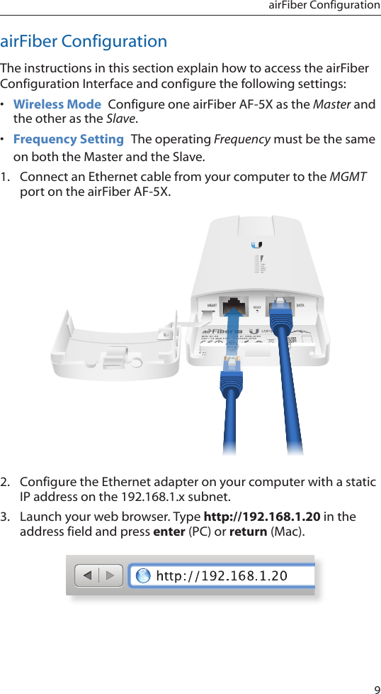
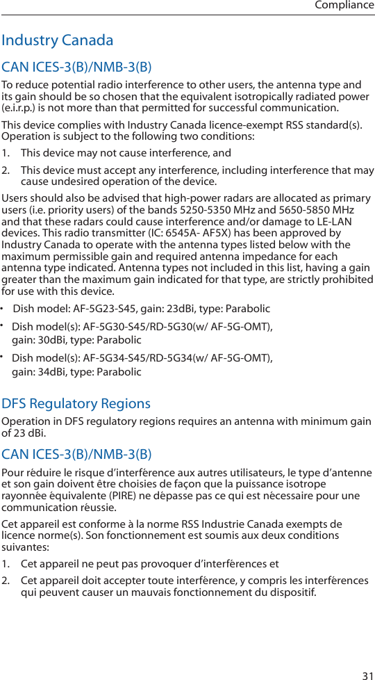
![35Declaration of ConformityDeclaration of ConformityČesky [Czech]UBIQUITI NETWORKS tímto prohla uje, e tento UBIQUITI NETWORKS device, je ve shod se základními po adavky a dal ími p íslu n mi ustanoveními sm rnice 1999/5/ES.Dansk [Danish]Undertegnede UBIQUITI NETWORKS erklærer herved, at følgende udstyr UBIQUITI NETWORKS device, overholder de væsentlige krav og øvrige relevante krav i direktiv 1999/5/EF.Nederlands [Dutch]Hierbij verklaart UBIQUITI NETWORKS dat het toestel UBIQUITI NETWORKS device, in overeenstemming is met de essentiële eisen en de andere relevante bepalingen van richtlijn 1999/5/EG.Bij deze verklaart UBIQUITI NETWORKS dat deze UBIQUITI NETWORKS device, voldoet aan de essentiële eisen en aan de overige relevante bepalingen van Richtlijn 1999/5/EC.EnglishHereby, UBIQUITI NETWORKS, declares that this UBIQUITI NETWORKS device, is in compliance with the essential requirements and other relevant provisions of Directive 1999/5/EC.Eesti [Estonian]Käesolevaga kinnitab UBIQUITI NETWORKS seadme UBIQUITI NETWORKS device, vastavust direktiivi 1999/5/EÜ põhinõuetele ja nimetatud direktiivist tulenevatele teistele asjakohastele sätetele.Suomi [Finnish]UBIQUITI NETWORKS vakuuttaa täten että UBIQUITI NETWORKS device, tyyppinen laite on direktiivin 1999/5/EY oleellisten vaatimusten ja sitä koskevien direktiivin muiden ehtojen mukainen.Français [French]Par la présente UBIQUITI NETWORKS déclare que l’appareil UBIQUITI NETWORKS, device est conforme aux exigences essentielles et aux autres dispositions pertinentes de la directive 1999/5/CE.Deutsch [German]Hiermit erklärt UBIQUITI NETWORKS, dass sich dieses UBIQUITI NETWORKS Gerät in Übereinstimmung mit den grundlegenden Anforderungen und den anderen relevanten Vorschriften der Richtlinie 1999/5/EG befindet. (BMWi)Ελληνική [Greek]ΜΕ ΤΗΝ ΠΑΡΟΥΣΑ UBIQUITI NETWORKS ΔΗΛΩΝΕΙ ΟΤΙ UBIQUITI NETWORKS device, ΣΥΜΜΟΡΦΩΝΕΤΑΙ ΠΡΟΣ ΤΙΣ ΟΥΣΙΩΔΕΙΣ ΑΠΑΙΤΗΣΕΙΣ ΚΑΙ ΤΙΣ ΛΟΙΠΕΣ ΣΧΕΤΙΚΕΣ ΔΙΑΤΑΞΕΙΣ ΤΗΣ ΟΔΗΓΙΑΣ 1995/5/ΕΚ. Magyar [Hungarian]Alulírott, UBIQUITI NETWORKS nyilatkozom, hogy a UBIQUITI NETWORKS device, megfelel a vonatkozó alapvetõ követelményeknek és az 1999/5/EC irányelv egyéb elõírásainak.Íslenska [Icelandic]Hér me l sir UBIQUITI NETWORKS yfir ví a UBIQUITI NETWORKS device, er í samræmi vi grunnkröfur og a rar kröfur, sem ger ar eru í tilskipun 1999/5/EC.](https://usermanual.wiki/Ubiquiti/AF5X/User-Guide-2548453-Page-37.png)
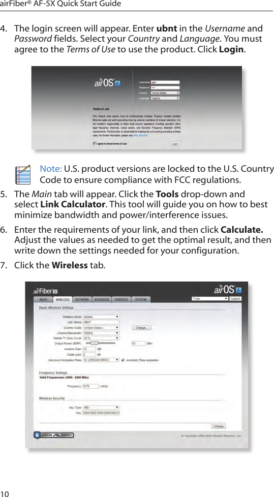
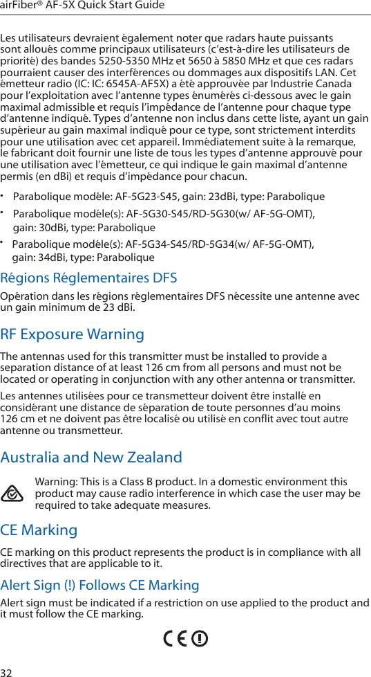
![36airFiber® AF-5X Quick Start GuideItaliano [Italian]Con la presente UBIQUITI NETWORKS dichiara che questo UBIQUITI NETWORKS device, è conforme ai requisiti essenziali ed alle altre disposizioni pertinenti stabilite dalla direttiva 1999/5/CE.Latviski [Latvian]Ar o UBIQUITI NETWORKS deklarē, ka UBIQUITI NETWORKS ierīce, atbilst Direktīvas 1999/5/EK būtiskajām prasībām un citiem ar to saistītajiem noteikumiem.Lietuviškai [Lithuanian]UBIQUITI NETWORKS deklaruoja, kad šis UBIQUITI NETWORKS įrenginys atitinka esminius reikalavimus ir kitas 1999/5/EB Direktyvos nuostatas.Malti [Maltese]Hawnhekk, UBIQUITI NETWORKS, jiddikjara li dan UBIQUITI NETWORKS device, jikkonforma mal- ti ijiet essenzjali u ma provvedimenti o rajn relevanti li hemm fid-Dirrettiva 1999/5/EC.Norsk [Norwegian]UBIQUITI NETWORKS erklærer herved at utstyret UBIQUITI NETWORKS device, er i samsvar med de grunnleggende krav og øvrige relevante krav i direktiv 1999/5/EF.Slovensky [Slovak]UBIQUITI NETWORKS t mto vyhlasuje, e UBIQUITI NETWORKS device, sp a základné po iadavky a v etky príslu né ustanovenia Smernice 1999/5/ES.Svenska [Swedish]Härmed intygar UBIQUITI NETWORKS att denna UBIQUITI NETWORKS device, står I överensstämmelse med de väsentliga egenskapskrav och övriga relevanta bestämmelser som framgår av direktiv 1999/5/EG.Español [Spanish]Por medio de la presente UBIQUITI NETWORKS declara que el UBIQUITI NETWORKS device, cumple con los requisitos esenciales y cualesquiera otras disposiciones aplicables o exigibles de la Directiva 1999/5/CE.Polski [Polish]Niniejszym, firma UBIQUITI NETWORKS o wiadcza, e produkt serii UBIQUITI NETWORKS device, spełnia zasadnicze wymagania i inne istotne postanowienia Dyrektywy 1999/5/EC.Português [Portuguese]UBIQUITI NETWORKS declara que este UBIQUITI NETWORKS device, está conforme com os requisitos essenciais e outras disposições da Directiva 1999/5/CE.Română [Romanian]Prin prezenta, UBIQUITI NETWORKS declară că acest dispozitiv UBIQUITI NETWORKS este în conformitate cu cerințele esențiale și alte prevederi relevante ale Directivei 1999/5/CE.PH020315](https://usermanual.wiki/Ubiquiti/AF5X/User-Guide-2548453-Page-38.png)