Ubiquiti LBE5AC Access Point User Manual LiteBeam LBE 5AC 23 Quick Start Guide
Ubiquiti Networks, Inc. Access Point LiteBeam LBE 5AC 23 Quick Start Guide
Ubiquiti >
Contents
Manual Part1
5 GHz, 23 dBi airMAX® CPE
with InnerFeed® Technology
Model: LBE-5AC-23
Introduction
Thank you for purchasing the Ubiquiti Networks®
LiteBeam™ac. This Quick Start Guide is designed to guide you
through installation and also includes warranty terms.
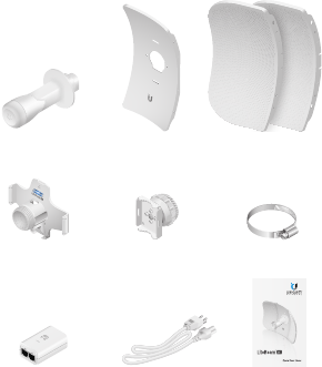
Package Contents
Antenna Feed Center Reflector
Panel
Side Reflector Panels
(Qty. 2)
Feed Receiver Ball Joint Mount Metal Strap
5 GHz, 23 dBi airMAX® CPE
with InnerFeed® Technology
Model: LBE-5AC-23
Gigabit PoE (24V, 0.3A)
with Mounting Bracket
Power Cord Quick Start Guide
Products may be different from pictures and are subject to change without notice.
TERMS OF USE: Ubiquiti radio devices must be professionally installed. Shielded Ethernet
cable and earth grounding must be used as conditions of product warranty. TOUGHCable™ is
designed for outdoor installations. It is the customer’s responsibility to follow local country
regulations, including operation within legal frequency channels, output power, and Dynamic
Frequency Selection (DFS) requirements.
Installation Requirements
• 7 mm socket wrench or screwdriver
• Shielded Category 5 (or above) cabling should be used for
all wired Ethernet connections and should be grounded
through the AC ground of the PoE.
We recommend that you protect your networks from
harmful outdoor environments and destructive ESD events
with industrial‑grade, shielded Ethernet cable from Ubiquiti
Networks. For more details, visit www.ubnt.com/toughcable
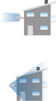
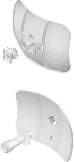
Application Examples
The LiteBeam ac mounted outdoors with the reflector
installed provides directional outdoor coverage (gain
reflector‑dependent).
The LiteBeam ac mounted outdoors without the reflector
installed provides outdoor‑to‑indoor coverage using the 3 dBi
Antenna Feed only.
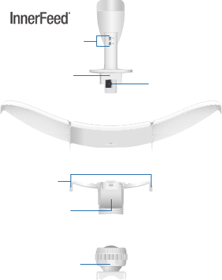
Hardware Overview
Bottom View
Technology
Reset Button
Lock Nut
Antenna Feed
Securing
Arms
Port Cover
Reflector Assembly
Feed Receiver
Ball Joint Mount
Ethernet Port
LEDs
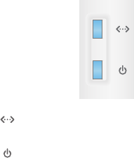
LEDs
Ethernet The LED will light steady blue when an
active Ethernet connection is made and flash when
there is activity.
Power The LED will light blue when the device is
connected to a power source.
Button
Reset To reset to factory defaults, press and hold the Reset
button for more than 10 seconds while the LiteBeamac is
already poweredon. Alternatively, the LiteBeam ac may be
reset remotely via a Reset button located on the bottom of the
Gigabit PoEadapter.
Port
Ethernet Supports 10/100/1000 connections and passive PoE.
This port should be connected to the LAN and DHCP server.
Hardware Installation
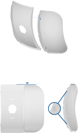
1. Assemble the antenna reflector by attaching the Side
Reflector Panels to the Center Reflector Panel:
a. Insert the heads of the two mounting studs on the
Center Reflector Panel into the large opening of the
slotted holes of a Side Reflector Panel.
b. Slide the Side Reflector Panel down until the top edges
of the panels align. The Side Reflector Panel is captured
when both heads of the mounting studs are positioned
over the narrow opening of the slotted holes.
c. Repeat the assembly for the other Side Reflector Panel.
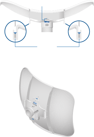
2. Hold the reflector assembly by hand (do not use a tabletop
or flat surface) and insert the Feed Receiver into the
reflector assembly to secure the panels:
a. Align the arrows on the Center Reflector Panel and the
Feed Receiver, and insert both edges of the Side Reflector
Panels and Center Reflector Panels into the Securing Arms
of the Feed Receiver.
Arrows
Securing Arms
b. Insert the Feed Receiver into the Center Reflector Panel by
pressing the top and bottom snap hooks into the slots
of the Center Reflector Panel.
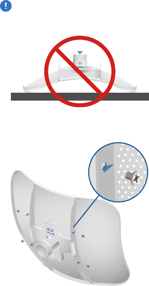
WARNING: Do not install the Feed Receiver into the
reflector assembly by pushing down onto a tabletop or
other flat surface as this can deform the panels. Hold the
reflector assembly by hand.
3. (Optional) For additional support, attach four M3x4
self‑tapping screws (not included) to the antenna
assembly.
4. Attach the Ball Joint Mount to the Feed Receiver by turning
the lock nut clockwise by hand. Do not tighten the nut.
5. Insert the Antenna Feed into the Feed Receiver until the feed
locks into place.