Ubiquiti UAPM 802.11 b/g/n 1x2 MIMO NETWORKING DEVICE User Manual UniFi AP Mini User Guide
Ubiquiti Networks, Inc. 802.11 b/g/n 1x2 MIMO NETWORKING DEVICE UniFi AP Mini User Guide
UserManual.wiki
>
Ubiquiti
>
UAPM User Manual
User Manual
Navigation menu
Upload a User Manual
Namespaces
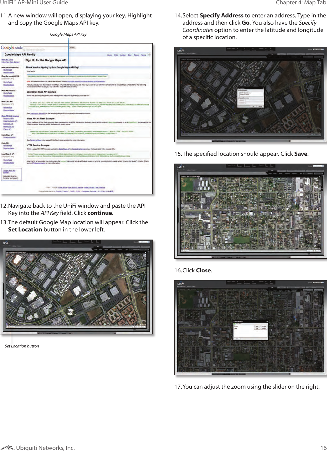
Wiki Guide
HTML
PDF
Info
Views
User Manual
Discussion / Help
Navigation
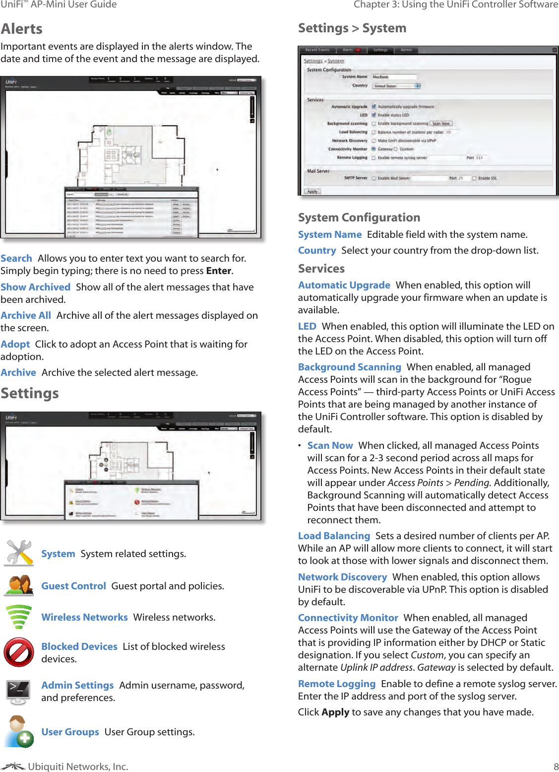
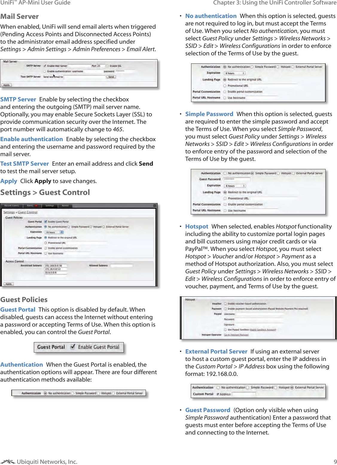
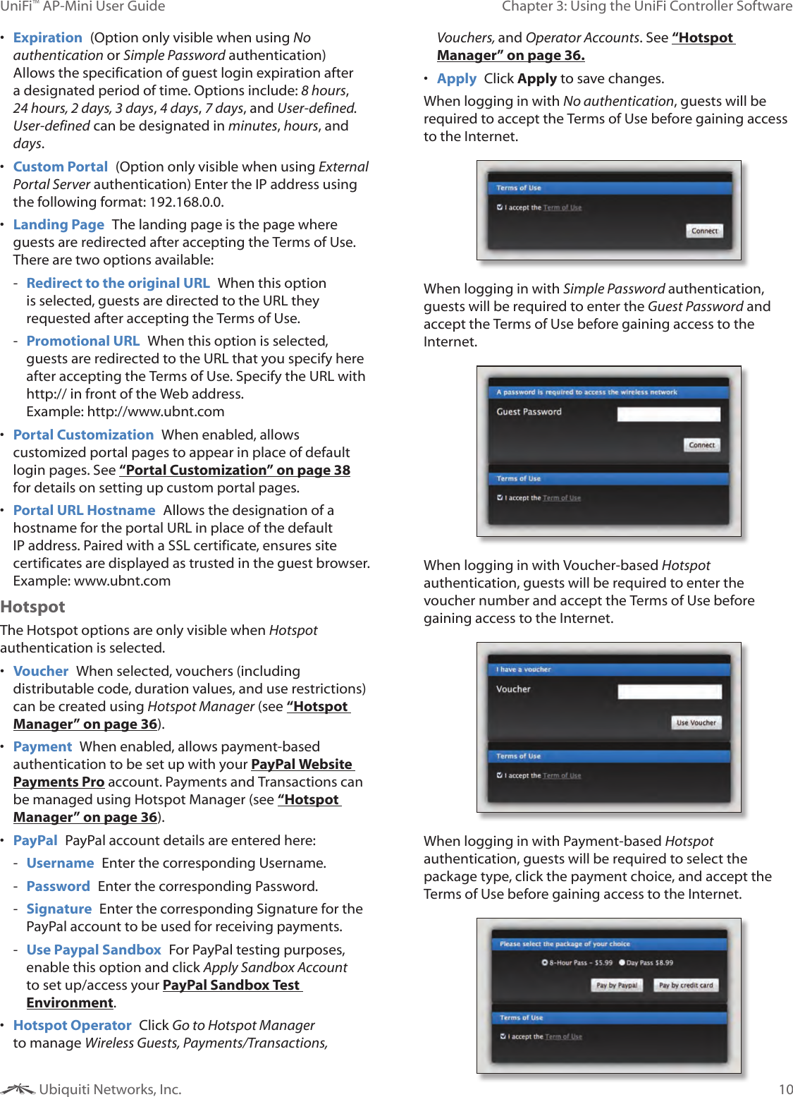
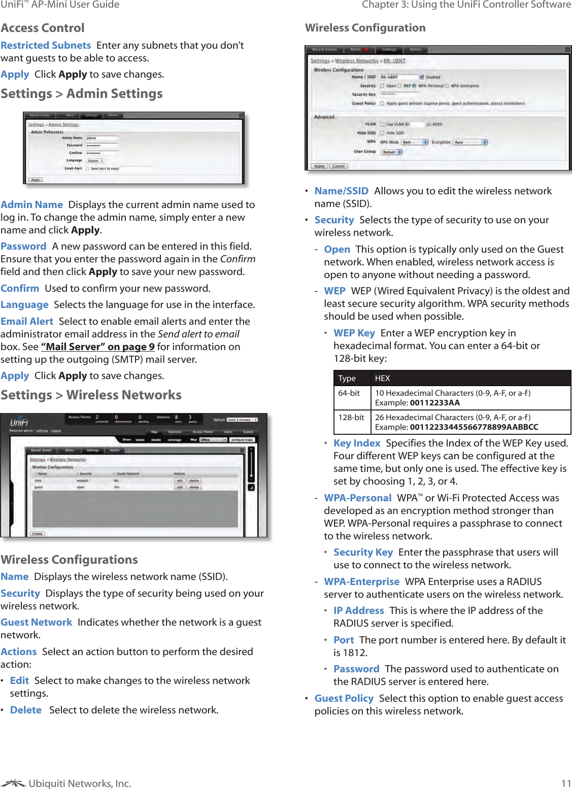
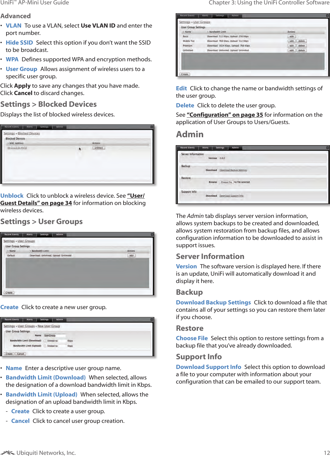
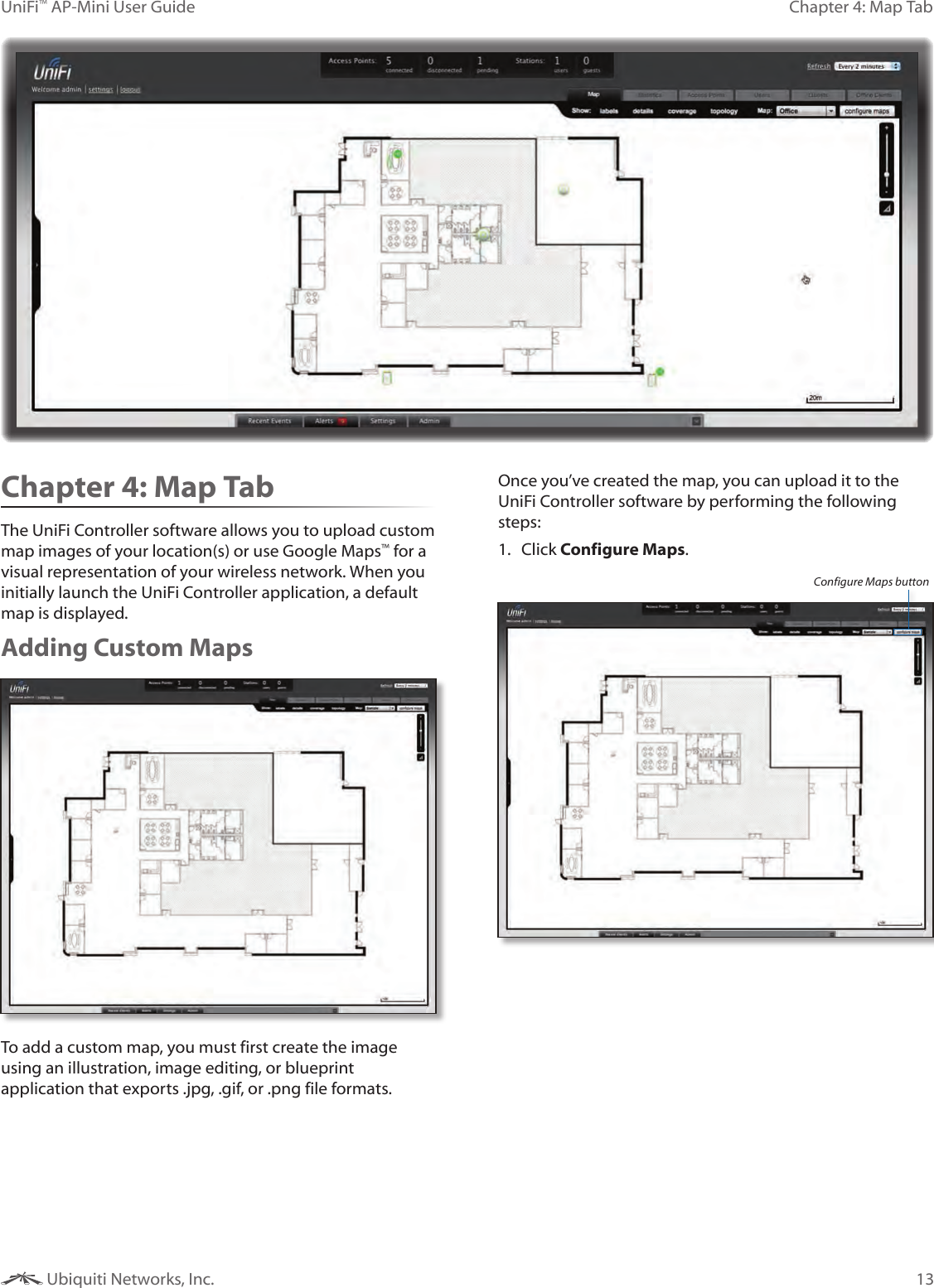
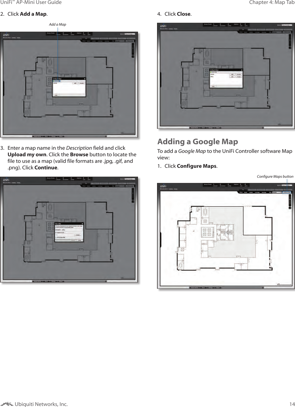
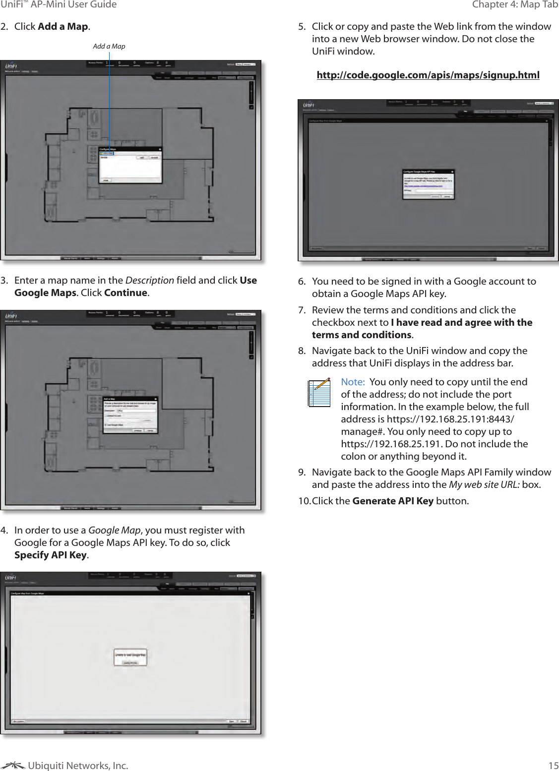
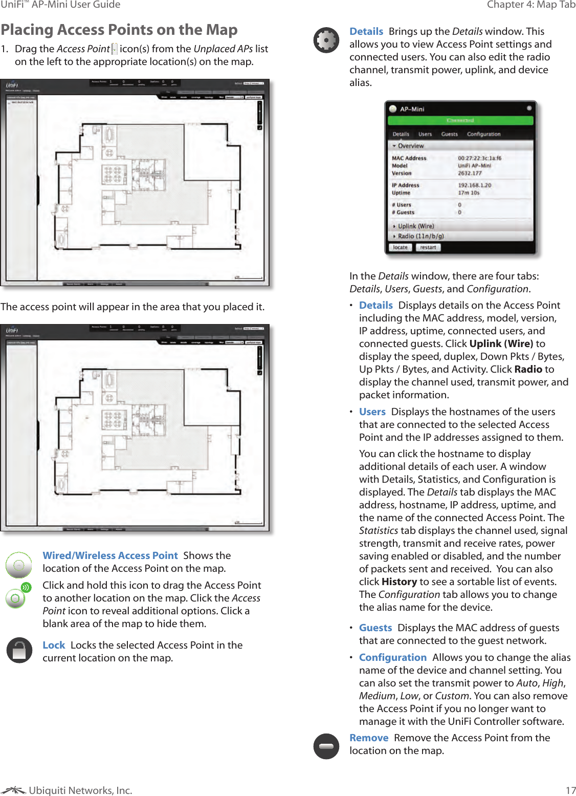
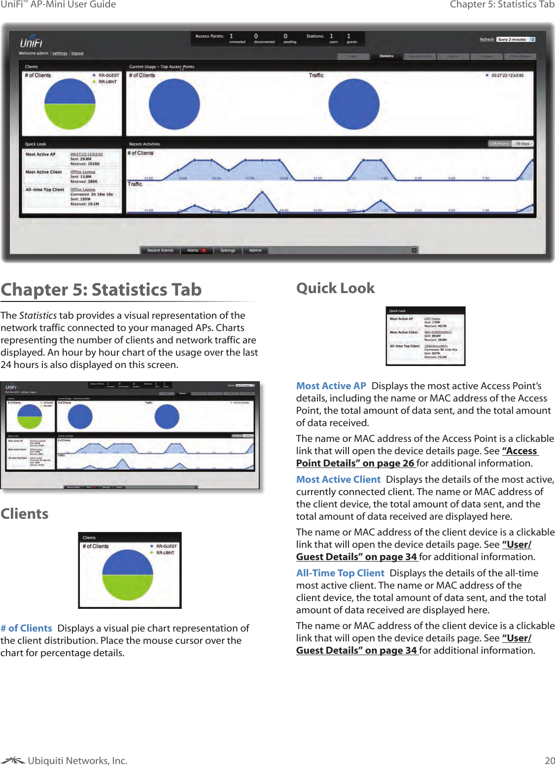
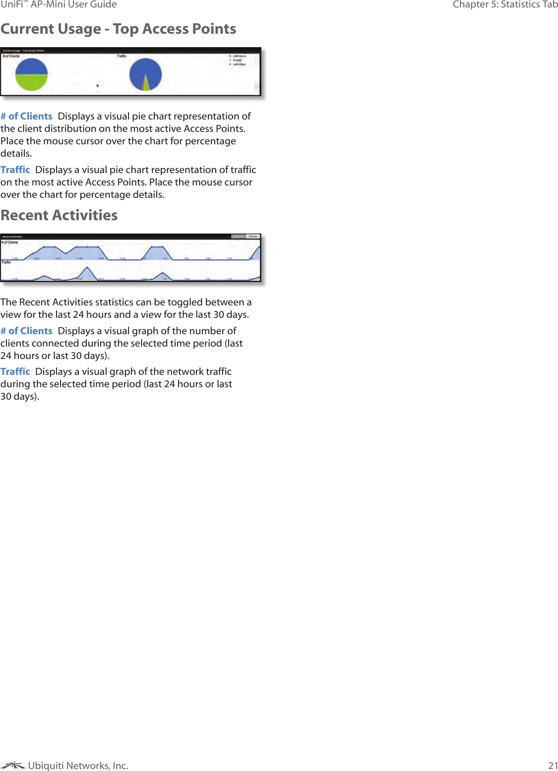
![7Chapter 3: Using the UniFi Controller SoftwareUniFi™ AP-Mini User Guide Ubiquiti Networks, Inc.Chapter 3: Using the UniFi Controller SoftwareThe UniFi Controller software that comes with your UniFi AP-Mini has a browser-based interface for easy configuration and management. To access the interface, perform the following steps:1. Launch the UniFi Controller application if hasn’t already been started. •Mac users: Go > Applications > UniFi •Windows users: Start > All Programs > Ubiquiti UniFi. 2. The UniFi login screen will appear. Enter the admin name and password in the appropriate fields and click Login. Interface TabsThe UniFi software consists of six primary tabs. This User Guide covers each tab with a chapter. For details on a specific tab, refer to the appropriate chapter. • “Map Tab” on page 13• “Statistics Tab” on page 20• “Access Points Tab” on page 22• “Users Tab” on page 23• “Guests Tab” on page 24• “Offline Clients Tab” on page 25Common Interface OptionsThe common interface options are accessible from all tabs in the UniFi interface. Access Points• connected Drop-down clickable list of all of the Access Points that are online. • disconnected Displays a list of Access Points that were previously online but are no longer accessible.• pending Drop-down clickable list of all of the Access Points that are not yet managed but are available for management. Stations• users Displays the total number of users connected to the primary network.• guests Displays the total number of users connected to the guest network.Recent EventsDisplays a list of recent events including the date and time the event occurred and the details of the event. The User and Access Point names are clickable links. Event Slider Move the slider right and left to navigate between pages of events. Search Allows you to enter text you want to search for. Simply begin typing; there is no need to press Enter.Clicking on an Event Device LinkThe event messages have clickable links [in brackets underlined in gray text] for AP (see “Access Point Details” on page 26), User, and Guest (see “User/Guest Details” on page 34). Details vary based on the selection.](https://usermanual.wiki/Ubiquiti/UAPM/User-Guide-1594016-Page-10.png)